Graco Series A Datasheet

308–092
Rev. C
Supersedes B
0211
INSTRUCTIONS-PARTS
LIST
INSTRUCTIONS
This
manual contains important
warnings and information.
READ AND KEEP FOR REFERENCE.
19 LITER (5 GALLON) PAIL SIZE
Pneumatic
Elevator Cart
FOR
CHECK-MA
TE
200 AND CHECK-MA
TE450 PUMPS
Model 224–137, Series A
14 bar (200 psi) Maximum Air Input Pressure
Table
of Contents
Warnings 2.
. . . . . . . . . . . . . . . . . . . . . . . . . . . . . . . . . . . . .
Setup 3
. . . . . . . . . . . . . . . . . . . . . . . . . . . . . . . . . . . . . . . . .
Operation 4
. . . . . . . . . . . . . . . . . . . . . . . . . . . . . . . . . . . . .
Troubleshooting 6
. . . . . . . . . . . . . . . . . . . . . . . . . . . . . . . .
Service 6
. . . . . . . . . . . . . . . . . . . . . . . . . . . . . . . . . . . . . . .
Parts 8
. . . . . . . . . . . . . . . . . . . . . . . . . . . . . . . . . . . . . . . . .
Accessories 10
. . . . . . . . . . . . . . . . . . . . . . . . . . . . . . . . . .
Dimensions 11
. . . . . . . . . . . . . . . . . . . . . . . . . . . . . . . . . . .
Technical
Data
11.
. . . . . . . . . . . . . . . . . . . . . . . . . . . . . . .
Warranty 12
. . . . . . . . . . . . . . . . . . . . . . . . . . . . . . . . . . . . .
Graco T
oll-Free Phone Number
12.
. . . . . . . . . . . . . . . .
GRACO INC. P.O. BOX 1441
MINNEAPOLIS, MN
55440–1441
COPYRIGHT
1991, GRACO INC.
Graco
Inc. is registered to I.S. EN ISO 9001

Symbols
Warning Symbol
WARNING
This
symbol alerts you to the possibility of serious
injury or death if you do not follow the instructions.
Caution Symbol
CAUTION
This
symbol alerts you to the possibility of damage to
or destruction of equipment if you do not follow the
instructions.
WARNING
INSTRUCTIONS
EQUIPMENT MISUSE HAZARD
Equipment
misuse can cause the equipment to rupture or malfunction and result in serious injury
.
D
This equipment is for professional use only
.
D
Read all instruction manuals, tags, and labels before operating the equipment.
D
Use the equipment only for its intended purpose. If you are not sure, call your Graco distributor
.
D
Do not alter or modify this equipment.
D
Check equipment daily
. Repair or replace worn or damaged parts immediately
.
D
Do not exceed 14 bar (200 psi) maximum air input pressure to the elevator cart.
D
Do not use hoses to pull equipment.
D
Route hoses away from traffic areas, sharp edges, moving parts, and hot surfaces. Do not expose
Graco hoses to temperatures above 82
_
C (180
_
F) or below –40
_
C (–40
_F).
DW
ear hearing protection when operating this equipment.
D
Comply with all applicable local, state, and national fire, electrical, and safety regulations.
MOVING
P
ARTS HAZARD
Moving
parts, such as the elevator tube and frame slides, can pinch or amputate your fingers.
D
Keep clear of all moving parts when starting or operating the equipment.
D
Keep clear of the elevator tube, frame slides, and the frame of the cart when operating the equip
-
ment.
D
Keep clear of the wiper plate and the lip of the fluid container when operating the equipment.
D
Before servicing the equipment, follow the
Pressure Relief Procedure
in your separate pump
manual to prevent the equipment from starting unexpectedly
.

Setup
NOTE:
Reference numbers and letters in parentheses
in the text refer to the callouts in the figures and the
parts drawing.
See page 10 for accessories available from Graco. If
you supply your own accessories, be sure they are
adequately sized and pressure-rated to meet the
system’
s requirements.
Mounting the Pump on the Cart
CAUTION
To
avoid tip-over
, the cart must be on a flat and level
surface. Failure to follow this caution could result in
injury or equipment damage.
Refer to Fig. 1. The pail stop (15) and the clamps (13),
screws (14) and nuts (7) used to mount the pump are
shipped loose.
1.
Slide the pail stop (15) onto the uprights (A) at the
rear of the cart. Adjust the stop to the desired
position.
2.
Set the pump (B) onto the cart so the baseplate of
the air motor rests on the pump supports (C).
Orient the pump fluid outlet (D) as shown in Fig. 1.
T
wo of the pump tie rods (E) will rest against the
pump supports (C). Hold the pump in this position
to keep it from tipping.
3.
Fasten the clamps (13) around the two tie rods.
Insert the four screws (14) through the clamps
from the front, and secure from the rear using the
four nuts (7).
4.
Install Wiper Plate 222–812 (carbon steel) or
222–909 (stainless steel) on the pump as ex
-
plained in separate instruction manual 308–049.
5.
Install Cart Accessory Kit 224–376 as explained in
separate manual 308–087 or 308–199.
Fig. 1
15
13
14
7
A
B
C
D
E
0256

4 308-092
Operation
WARNING
MOVING P
ARTS HAZARD
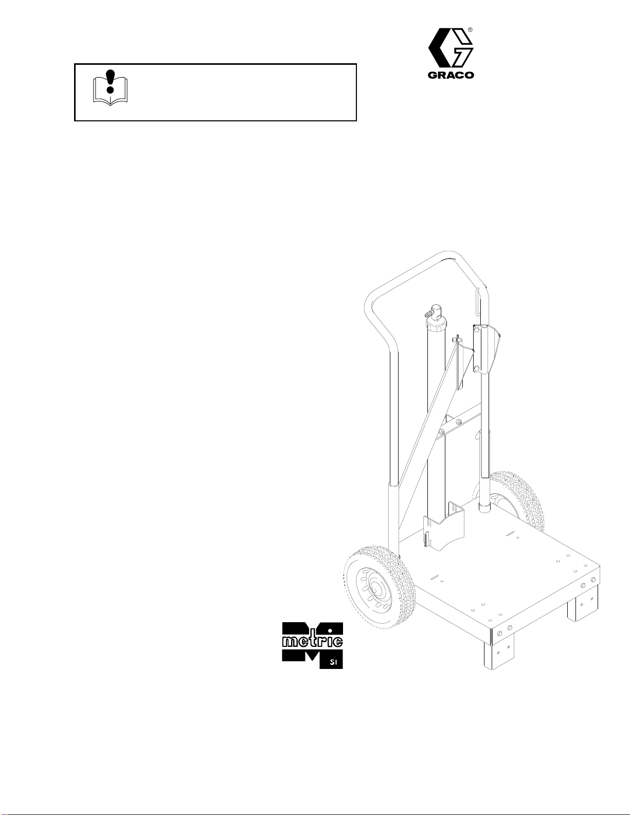
The elevator tube (F) and frame slides
(G) move up and down when the eleva
-
tor is in operation, and can pinch fingers
or hands caught between them and the cart frame.
Keep your hands away from the elevator tube,
frame slides, and the frame of the cart when the
elevator is in operation. See Fig. 2.
The wiper plate (K) moves downward as the eleva
-
tor is lowered, and can pinch or amputate fingers or
hands caught between it and the lip of the fluid
container
. Keep your hands away from the wiper
plate and the lip of the fluid container when the
elevator is in operation. See Fig. 2.
Wiper Plates 222–812 and 222–909
Wiper
plates 222–812 and 222–909 are shipped for
use with straight-sided pails on a 19 liter (5 gallon)
ram. The plates must be modified for use with this
pneumatic elevator cart, or for use with tapered pails.
Refer to the separate wiper plate manual 308–049 for
details.
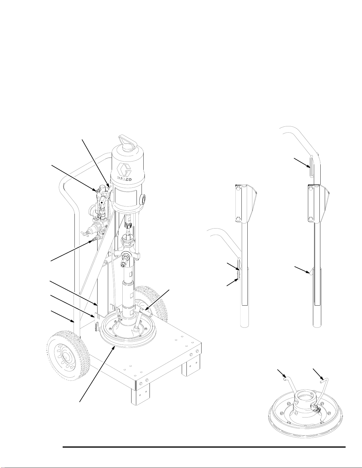
Raising the Elevator and Positioning the
Pail
NOTE: T
o ensure smooth operation of the elevator
,
grease the vertical portions of the cart handle so the
frame slides (G) move up and down easily
.
1.
Disconnect the female quick coupler from the
pump air inlet fitting (L) and connect it to the air
inlet fitting (3n) on the elevator
. T
urn on the main
air
. See Fig. 2.
2.
Raise the elevator to its maximum height, so the
hanger (H) on the cart handle is below the hook (J)
on the elevator frame.
3.
Place a 19 liter (5 gallon) pail of fluid on the base
of the cart. Slide the pail back against the pail stop
(15). The pail stop is adjustable to four positions,
to properly align the pail with the wiper plate (K).
4.
Make the fluid surface concave by scooping fluid
from the center of the pail to the sides.
Lowering the Elevator
1. Pull
the hanger (H) upward and hold it firmly
against the handle of the cart. Disconnect the
female quick coupler from the elevator air inlet
fitting (3n) and connect it to the pump air inlet
fitting (L). After a short delay
, the weight of the
pump will cause the elevator to move downward.
Continue to hold the hanger (H) against the cart
handle until the hook (J) on the frame is low
enough to prevent it from engaging the hanger
.
See Fig. 2.
2.
If necessary
, push down on the top of the pump to
help the wiper plate (K) enter the pail. When the
wiper plate enters the pail, open the wiper plate
vent (M) and leave it open until fluid appears at the
vent hole. Close the vent.
3.
Start the pump as explained in the separate pump
manual.
4.
When the pail is empty
, change pails as follows.
Changing Pails
To
raise the pump out of an empty pail:
WARNING
T
o reduce the risk of serious injury whenever you
are instructed to relieve pressure, always follow the
Pressure Relief Procedure
in your separate pump
manual.
1.
Stop the pump.
Relieve the pressure.
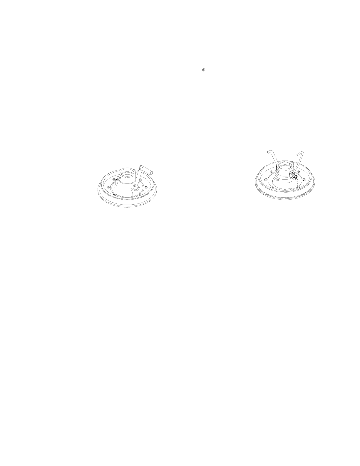
2.
Set the air release toggle valve (N) to the open
position (down). The toggle valve directs air under
the wiper plate, making it easier to pull the plate
out of the pail. See Fig. 2.
3.
For Stainless Steel W
iper Plate 222–909 only:
Rotate the long handle (P) in the wiper plate
housing 45
clockwise
and pull the handle up
-
ward (it should travel about 1/2 inch up and down).
This opens a passage for air to assist in getting
the plate out of the pail. See the Detail in Fig. 2.
4.
Disconnect the female quick coupler from the
pump air inlet fitting (L), and connect it to the
elevator air inlet fitting (3n). After a short delay, the
elevator will begin to raise the pump from the pail.

5308-092
Operation
5.
As the wiper plate (K) nears the top of the pail, the
seal between the wiper and pail will decrease and
the plate may not come completely out of the pail.
If you are using Stainless Steel W
iper Plate
222–909,
push the long handle (P) back down and
rotate it 45
counterclockwise
to lock it.
The elevator will lift the pump and pail together
. Let
the elevator rise to its maximum height, so the
hanger (H) on the cart handle is below the hook (J)
on the elevator frame, then just pull the pail of
f the
plate.
NOTE:
If the plate is stuck at the bottom of the pail
and doesn’t come out at all, the elevator will pull the
pail up along with the plate. If this happens, allow the
elevator to rise to its full height, then open the wiper
plate vent (M). This will make it possible to pull the pail
of
f the plate. Check for a blockage in the air release
line, as explained on page 6.
6.
Place the full pail on the cart base and position as
explained at left.
F
G
K (Model 222–812)
L
3n H
J
15 M
N
Detail Showing
Hanger and Hook
(Elevator Raised)
Detail Showing
Hanger and Hook
(Elevator Lowered)
J
H
0258 0259
Detail Showing
Stainless Steel W
iper Plate
222–909
PM
0252A
01115
Fig. 2

6 308-092
Troubleshooting
Problem Cause Solution
Elevator won’t raise the pump.
W
orn cup packing in the elevator
tube.
Apply air to the elevator and check if
air is escaping at the bottom of the
outer elevator tube (3c). Replace the
packing.
Clogged or dirty air valve housing.
Inspect; clean.
Elevator won’t pull the wiper plate
out of the pail.
Clogged air release line or defective
air release toggle valve.
With the pail removed from the wiper
plate, apply air to the elevator
. Set
the air release toggle valve to the
open position (down). Listen for air on
the underside of the wiper plate. If no
air is heard, the air release toggle
valve or tube is clogged. Clean or
replace. See manual 308–087 or
308–199 for parts.
Clogged air assist check valve on the
wiper plate.
Clean. See manual 308–049.
Service
WARNING
T
o reduce the risk of serious injury whenever you
are instructed to relieve pressure, always follow the
Pressure Relief Procedure
in your separate pump
manual.
1.
Before servicing any part of the system,
relieve
the pressure.
2.
Lower the elevator as explained on page 4.
Remove the air release toggle valve (N). See Fig.
2.
3.
Remove the screws, nuts and washers holding the
elevator (3) to the cart base plate (10) and frame
(12). Refer to the parts drawing on page 8.
4.
Unscrew the air valve housing (3m). See Fig. 3. If
clogged or dirty
, clean.
5.
Unscrew the top and bottom caps (3a and 3h).
Remove and inspect the gasket (3b) inside the top
cap.
6.
Push the elevator tube (3f) up and pull it out the
top of the outer elevator tube (3c). Slide the spacer
(3g) of
f the bottom of the elevator tube (3f).
7.
Unscrew the piston (3e) from the tube (3f). Disas
-
semble the piston assembly
.
8.
Replace the leather cup packing (3j) if it is worn.
Lubricate the outer diameter of the packing. Reas
-
semble the piston.
9.
Screw the piston (3e) into the elevator tube (3f).
Slide the spacer (3g) onto the bottom of the eleva
-
tor tube (3f). Slide the tube down into the outer
elevator tube (3c) until its bottom threads protrude.
Screw the bottom cap onto the tube (3f).
10.
Place the gasket (3b) into the inner groove of the
top cap (3a). Screw the top cap onto the outer
elevator tube (3c).
11.
Screw the air valve housing (3m) into the top cap
(3a). Install elevator onto cart base (10) and frame
(12), using screws, nuts and washers. Reinstall the
air release toggle valve (N). See Fig. 2.

7308-092
Service
3a
3b
3d
3e
3f
3g
3h
3j
3k
Ref. No. 3 Includes
Items 3a–3p
3c
3m
3n
3p
0215
Fig. 3
1
2
Lubricate
outer diameter
.
Lubricate inside diameter above the piston (3e).
1
2

Parts
Model 224–137, Series A
Includes items 1–21
1
2
4
5
6
7
89
10
11
12
13
14
15
16 17
18
19
20
21
89
4(Ref)
12 (Ref)
0216
1See
Detail on page 9.
13

Parts
Model 224–137, Series A
Includes items 1–21
Ref.
No. Part
No.
Description Qty.
1 186–799
CHANNEL, foot
2
2 100–057 SCREW
, cap, hex hd;
5/16–18 unc–2a;
3/4” (19 mm) long 2
3 224–138 ELEVAT
OR (includes items 3a–3p;
see detail at right)
1
3a 186–794 . CAP
, elevator, top
1
3b 158–109 . GASKET; rubber 1
3c 224–139 .
TUBE, elevator
1
3d 100–155 . NUT
, jam, hex; 5/8–16
1
3e 164–249 . PISTON 1
3f 164–247 .
TUBE, guide, elevator
1
3g 164–248 . SPACER 1
3h 186–793 . CAP
, elevator
, bottom
1
3j 150–179 . P
ACKING, cup; leather
1
3k 156–306 . W
ASHER, flat
1
3m 187–025 .
HOUSING, valve, air
1
3n 169–969 .
FITTING, quick disconnect;
1/8 npt(m) 1
3p 100–139 .
PLUG, pipe; 1/8 npt
1
4 186–863
HANDLE, cart
1
5 186–865 HANGER 1
6 100–609 SCREW
, machine, pan hd;
1/4–20 unc–2a;
3/8” (10 mm) long 2
7 101–566 LOCKNUT
, with nylon insert;
3/8–16 4
8 111–303 NUT
, hex; 5/16–18 unc–2b
6
9 100–214 LOCKW
ASHER, spring;
5/16” size
6
10 224–141
BASE, cart
1
11 106–062
WHEEL, semi-pneumatic
2
12 224–140
FRAME, elevator
1
13 186–796 CLAMP 2
14 100–680 SCREW
, cap, hex hd;
3/8–16 unc–2a;
7/8” (22 mm) long 4
15 186–798 STOP
, pail
1
16 104–811
HUB CAP
2
17 101–242
RING, retaining
2
18 100–049 SCREW
, cap, hex hd;
1/2–13 unc–2a; 1” (25 mm) long
1
19 100–018 LOCKW
ASHER, spring; 1/2” size
1
20 101–044 W
ASHER, plain; 1/2” size
1
21 111–302 SCREW
, cap, hex hd;
5/16–18 unc–2a; 2” (51 mm) long
4
3a
3b
3d
3e
3f
3g
3h
3k
Ref. No. 3 Includes
Items 3a–3p
3m
3n
3p
0215
3c
3j

10 308-092
Accessories
Use Only Genuine Graco Parts and Accessories
Cart
Accessory Kit 224–376
Includes fittings and hoses required to use the cart
with a Check-Mate
t
pump and 222–812 or 222–909
Wiper Plates. Refer to Instruction Manuals 308–087 or
308–199.
19 Liter (5 Gal.) Carbon Steel W
iper Plate,
Model 222–812,
with buna-N and polyethylene wipers
PATENT
PENDING
Can
be used with both straight-sided and tapered
pails. Applies pressure on surface of highly viscous
fluids, to force fluid into the pump intake and assist
priming. Refer to Instruction Manual 308–049.
0212
19 Liter (5 Gal.) Stainless Steel W
iper Plate,
Model 222–909,
with PTFErcoated and polyethylene wipers
PATENT
PENDING
Can
be used with both straight-sided and tapered
pails. Applies pressure on surface of highly viscous
fluids, to force fluid into the pump intake and assist
priming. Refer to Instruction Manual 308–049.
01115
Manual
Change Summary
The
manual has been generally updated.

11308-092
Dimensions
Width
Across Wheels:
670 mm (26.34 in.)
0211
575.5 mm
(22.66 in.)
Technical
Data
Maximum
air input pressure
14 bar (200 psi)
.
. . . . . . . . . . . . . . . . . . . . . . . . . . . . . . . . . . . . . . . . .
Weight 34
kg (75 lb)
.
. . . . . . . . . . . . . . . . . . . . . . . . . . . . . . . . . . . . . . . . . . . . . . . . . . . . . . . . . . . . . .

12 308-092
Graco
W
arranty and Limitation of Liability
WARRANTY
Graco
warrants all equipment listed in this manual which is manufactured by Graco and bearing its name to be free from defects
in material and workmanship on the date of sale by an authorized Graco distributor to the original purchaser for use. Graco will,
for a period of twelve months from the date of sale, repair or replace any part of the equipment determined by Graco to be defec
-
tive. This warranty applies only when the equipment is installed, operated and maintained in accordance with Graco’
s written rec-
ommendations.
This warranty does not cover
, and Graco shall not be liable for general wear and tear
, or any malfunction, damage or wear
caused by faulty installation, misapplication, abrasion, corrosion, inadequate or improper maintenance, negligence, accident,
tampering, or substitution of non-Graco component parts. Nor shall Graco be liable for malfunction, damage or wear caused by
the incompatibility of Graco equipment with structures, accessories, equipment or materials not supplied by Graco, or the im
-
proper design, manufacture, installation, operation or maintenance of structures, accessories, equipment or materials not sup
-
plied by Graco.
This warranty is conditioned upon the prepaid return of the equipment claimed to be defective to an authorized Graco distributor
for verification of the claimed defect. If the claimed defect is verified, Graco will repair or replace free of charge any defective
parts. The equipment will be returned to the original purchaser transportation prepaid. If inspection of the equipment does not
disclose any defect in material or workmanship, repairs will be made at a reasonable charge, which charges may include the
costs of parts, labor
, and transportation.
THIS WARRANTY IS EXCLUSIVE, AND IS IN LIEU OF ANY OTHER WARRANTIES, EXPRESS OR IMPLIED,
INCLUDING
BUT NOT LIMITED TO WARRANTY OF MERCHANTABILITY OR WARRANTY OF FITNESS FOR A PARTICULAR PUR-
POSE.
Graco’
s sole obligation and buyer
’
s sole remedy for any breach of warranty shall be as set forth above. The buyer agrees that no
other
remedy (including, but
not limited to, incidental or consequential damages for lost profits, lost sales, injury to person or prop
-
erty
, or any other incidental or consequential loss) shall be available. Any action for breach of warranty must be brought within two
(2)
years of the date of sale.
GRACO MAKES NO WARRANTY, AND DISCLAIMS ALL IMPLIED WARRANTIES OF MERCHANTABILITY AND FITNESS
FOR A PARTICULAR PURPOSE IN CONNECTION WITH
ACCESSORIES, EQUIPMENT
, MA
TERIALS, OR COMPONENTS
SOLD BUT NOT MANUFACTURED BY GRACO.
These items sold, but not manufactured by Graco (such as electric motors,
switches, hose, etc.) are subject to the warranty
, if any
, of their manufacturer
. Graco will provide purchaser with reasonable assis
-
tance in making any claim for breach of these warranties.
For Sales to Canadian Customers:
Except
as expressly stated herein, Graco makers no
representations, warranties or conditions, express, implied or collateral, con
-
cerning
any goods or services sold, and
GRACO SHALL NOT BE LIABLE IN ANY MANNER FOR
any other representation,
warranty
or condition of any kind, whether arising by operation of law or otherwise, including but not limited to,
WARRANTIES OF
MERCHANTABLE QUALITY OR FITNESS FOR A PARTICULAR PURPOSE.
LIMITATION OF LIABILITY
In no event will Graco be liable for indirect, incidental, special or consequential damages resulting from Graco supplying equip
-
ment hereunder
, or for the furnishing, performance, or use of any products or other goods sold hereto, whether due to a breach of
contract, breach of warranty
, the negligence of Graco, or otherwise.
Graco
Phone Number
TO
PLACE AN ORDER
, contact your Graco distributor
, or call this number to identify the distributor closest to you:
1–800–367–4023 T
oll Free
Sales
Offices:
Atlanta, Chicago, Detroit, Los Angeles
Foreign Offices:
Belgium, Canada, England, Korea, Switzerland, France, Germany
, Hong Kong, Japan
GRACO INC. P.O. BOX 1441
MINNEAPOLIS, MN
55440–1441
PRINTED
IN U.S.A. 308–092 January 1991 Revised March 1996
Other manuals for Series A
66
This manual suits for next models
1
Table of contents
Other Graco Outdoor Cart manuals