manuals.online logo
Brands
  1. Home
  2. •
  3. Brands
  4. •
  5. Nova
  6. •
  7. Outdoor Cart
  8. •
  9. Nova 375-LF User manual

Nova 375-LF User manual

Operator’s Manual
Publish Date: 3-21-23
NVA-375-LF
North America
©NOVA Welding Industries
375-LF Welding Cart
MODEL: NVA-375-LF
SERIAL NUMBER:
APPLICATION:
DESCRIPTION: Long Frame Welding Cart with 375 lb. weight limit
AVOID PROBLEMS AND FRUSTRATIONS. READ THIS MANUAL BEFORE ATTEMPTING ASSEMBLY!
2
TABLE OF CONTENTS
SPECIAL NOTICE AND CALIFORNIA PROPOSITION 65 WARNING 4
SAFETY DISCLAIMER 5
GETTING STARTED (BEFORE ASSEMBLY, NEED-NEED TO KNOW INFORMATION) 6
SPECIFICATIONS 9
COMPONENT ID AND ASSEMBLY 10-22
RECYCLE. DO NOT DISCARD THIS PRODUCT IN THE TRASH!
• Though this cart should give years of service life, at some point
the welding cart may no longer be of service or value. The cart
should be recycled locally through metal and plastic recyclers.
• The primary material is steel. This is a readily recyclable materi-
al. Consult your local recyclers on how to present the unit for
recycling.
• Plastic and rubber components should be separated and broken
down into an acceptable form for recycling.
3
NOTICE:
Product Specications and features are subject to change without notice. While every at-
tempt has been made to provide the most accurate and current information possible at the
time of publication, this manual is intended to be a general guide and not intended to be
exhaustive in its content regarding safety, welding, or the operation/maintenance of this
unit. Due to multiple variables that exist in the welding eld and the changing nature of it
and of the NOVA Welding Industries does not guarantee the accuracy, completeness, au-
thority or authenticity of the information contained within this manual or of any infor-
mation offered during the course of conversation or business by any NOVA employee or
subsidiary. The owner of this product assumes all liability for its use and maintenance.
NOVA does not warrant this product or this document for tness for any particular pur-
pose, for performance/accuracy or for suitability of application. Furthermore NOVA does
not accept liability for injury or damages, consequential or incidental, resulting from the
use of this product or resulting from the content found in this document or accept claims
by a third party of such liability.
WARNING!
California Proposition 65 Warning:
This product, when used for welding or cutting, produces fumes or gases which
contain chemicals known to the State of California to cause birth defects and, in
some cases, cancer. (California Health & Safety Code § 25249.5 et seq.)
Warning: Cancer and/or Reproductive Harm
www.P65warnings.ca.gov
4
Safe operation and proper maintenance is your responsibility.
NOVA Welding Industries is dedicated to keeping safety a top priority. While we have compiled this operator’s manual to instruct you in basic
safe operation and maintenance of your NOVA product, it is no substitute for observing safe welding practices and behavior. Safe welding and
related operations require basic knowledge, experience and ultimately the exercise of common sense. Welding does signicant hazards to your
health and life! Exercise extreme caution and care in all activities related to welding or cutting. Your safety, health and even life depends upon
it.
WARNING! If you do not have proper knowledge or capability to safely assemble and operate this cart, seek professionals to assist
and instruct you.
While accidents are never planned, preventing an accident requires careful planning. Stay alert!
Please carefully read this manual before you start!
The warranty does not cover damage or harm created by improper use. neglect of the cart or failure to follow safe operating practices.
5
Safety Warnings, Dangers, Cautions and Instructions
NOTICE. This unit manual is intended for users with basic knowledge and skillset in weld-
ing. It is your responsibility to make certain that the use of this welder is restricted to per-
sons who have read, understand and follow the warnings and instructions in this manual. If
you or the operator needs further instruction, contact NOVA at 1-877 755-9353.
WARNING! High Frequency (HF) energy can interfere with the operation of pacemakers and
can damage pacemakers. Consult with your physician and pacemaker manufacturer before
entering an area where welding and cutting equipment is in operation and before using this
welder. Some pacemakers have limited shielding. Alert any users or customers of this po-
tential problem.
WARNING! Use approved safety glasses with wrap around shields and sides while welding
and working in the weld area or serious eye damage or loss of vision may result. Use a
grinding shield in addition to the safety glasses during chipping and grinding operations.
WARNING! When welding always use an approved welding helmet or shielding device
equipped with at least an equivalent of a shade 9 or greater. Increase the shade number
rating as amperage increase over 100 amps. Inspect helmet for cracks in lenses and in the
helmet. Keep lens covers in good condition and replace as necessary.
WARNING! Welding/cutting operations carry inherent risks which include but not limited to
possible cuts burns, electrical shocks, lung damage, eye damage and even death. Take all
appropriate measures to use proper Personal Protective Equipment (PPE). Always use
leather welding gloves, closed toe (preferably reinforced or steel toe leather shoes, and long
-sleeved flame resistant clothing (i.e. denim). Do not wear Poly/Nylon blend materials.
DANGER! Welding/cutting poses shock and electrocution risks. Keep this welding equip-
ment dry. Do not weld in the rain or where moisture accumulates. Use dry, rubber soled
shoes, gloves and clothing when welding. Do not rest or contact work clamp (ground) when
welding. Keep all parts of the body insulated from the part being welded when possible. Do
not touch terminals or connections while the unit is on. Consider all parts to be “live” at all
times even if no live work is being performed. Do not use frayed welding cables.
CAUTION! Fires are possible but also preventable while welding. Always remove flammable
rags, papers, and other materials from the weld area. Keep rags stored in an approved flame
proof canister. Keep a fully charged re extinguisher at hand. Remove any fuels, oils,
paint, pressurized spray cans, and chemicals from the weld area. Make sure any smoke/re
detectors are function properly. Do not weld on tanks, drums or barrels, especially if pres-
surized or sealed. Do not weld on any container that previously held fuel or chemicals.
Make sure the weld area is clear of flammable materials such as grass or wood shavings
solvents and fuels. Do not wear frayed or loose clothing. Visually inspect and recheck the
work area after welding looking for smoldering debris or flames.
WARNING! Welding gas cylinders are under high pressure. Keep all gas cylinders upright
and double chained to the welding cart or held safely in a safety holding pen. Never
transport gas cylinders in an enclosed car van or other vehicle. Transport gas cylinders se-
curely. Keep all cylinders capped while not in use or during transport. Replace the cap on
the cylinder when it is going to be more than 24 hours before use. Do not use or attempt
to repair faulty regulators. Never weld on gas cylinders. Keep gas cylinders away from di-
rect sparks.
6
Safety Warnings, Dangers, Cautions and Instructions
DANGER! Welding and cutting operations pose serious inhalation hazards. Some of these
hazards are immediate while others are cumulative in their effect. Do not weld in enclosed
spaces or in areas without adequate ventilation. Fumes and gases released in the welding
and cutting operations can be toxic. Use fans or respiration equipment to insure adequate
ventilation if you are welding in a shop or garage area. Do not weld on galvanized metal
under any circumstance. You may develop metal fume fever. Symptoms are similar to lu-
like symptoms. Seek medical advice and treatment if you are exposed to galvanized weld-
ing fumes.
If you experience any eye burning, nose or throat irritation while welding, these are signs
that you need more ventilation.
If you feel these symptoms:
• Stop work immediately and relocate work area with better ventilation.
• Wash and clean your face and hands.
• Stop work completely and seek medical help if irritation persists
DANGER! Never use brake cleaner or any chlorinated solvent to clean or degrease metal
scheduled to be welded or other related equipment in the area being welded. The heating
of this cleaner and its residue will create highly toxic phosgene gas. Small amounts of
this vapor are harmful and can lead to organ failure and death. If degreasing of a part is
necessary, use Acetone or an approved pre-weld cleaner. Use the proper personal protec-
tive equipment (PPE) when handling any cleaners/solvents.
DANGER! People with pacemakers should consult a physician and pacemaker manufactur-
er before welding. There is a potential for damage or serious malfunction resulting in
death. High Frequency energy (HF)/Electromagnetic Fields generated during welding can
interfere with pacemaker signals, even permanently damaging it. Some pacemakers offer
some shielding, but restrictions regarding amperage and HF starting of TIG arcs may be
placed upon the individual. Warn all potential bystanders that they should exit the work
area if they have a pacemaker or similar medical equipment before welding. Severe electri-
cal shock leading to injury or death may occur while using the plasma cutter if the user
becomes part of the circuit path. While the Amp output of the plasma cutter is limited, the
unit may produce an OCV of 300V or greater. Consult with a Physician if a pacemaker is
expected to be implanted.
DANGER! Never defeat or modify any safety guards or shields. Keep all safety covers and
shields in place.
Never place your ngers in or near a fan shroud or insert any object into the fan(s).
7
Safety Warnings, Dangers, Cautions and Instructions
CAUTION! Trip Hazards exist around welders. Cords, cables, welding leads and hoses pose
a trip hazard. Be aware of their location and inform others of their location. Tape and se-
cure them so they will stay out of high trafc areas.
CAUTION! Welded metal can stay hot long after welding is completed. Burns may occur.
Always wear gloves or use tongs/pliers when handling welded or cut metal. Remember
the heat from the metal may catch other material on re. Always have a re-proof area
ready to place welded components until they fully cool. Use soap stone or a metal marking
marker to label the metal as “HOT” to serve as a reminder to all present in the area.
CAUTION! Welding and cutting operations generate high levels of ultraviolet (UV) radiation
which can burn and damage skin and eyes. The intensity is so high that exposed skin and
eyes can burn in a few minutes of exposure. Minimize direct skin and eye exposure to this
intense form of radiation by using proper PPE and sun screen where appropriate.
CAUTION! Do not allow bystanders. Do not allow others without proper Personal Protec-
tion Equipment (PPE) suitable for welding to stand in the welding area or to observe weld-
ing and welding related activities. If protection is not readily available, use a welding
screen to separate the welding area from the rest of the area. If no protection or screen is
available, physically exclude them from the welding area by a wall or other solid divider.
Keep all pets and young children away from the welding area.
DANGER! When storing the pedal, make sure the switch on the pedal is turned to off or
disconnected before inserting into the pedal/accessory shelf.
8
Setup Guide
Getting Started
UNPACK YOUR UNIT.
Upon arrival, you will need to completely unpack your cart from the
box as soon as possible. It is important to identify any potential is-
sues or missing items with your cart. If any issue is noted, you
should contact NOVA and resolve it immediately.
Your packaged components should be laid out in a logical order.
Start by sorting bolts and washers by size, and then arranging the
other parts in order of need. Thoroughly inspect the parts and com-
ponents for damage. Check for the presence and general condition of
the parts. Some slight rubbing or chafng of some parts may be
present, but this is considered normal. Any blemishes like this can be
touched up with about any quality satin black spray enamel. If any
item is bent, missing, or otherwise damaged, please inform NOVA
within 72 hours of product receipt. NOTICE: Shipping damage claims
after 30 days may not be accepted unless extenuating circumstances
exist such as overseas deployment, etc. For the purpose of expedien-
cy, though, any missing fastener can be bought locally. See the parts/
expanded view page for sizes and quantities.
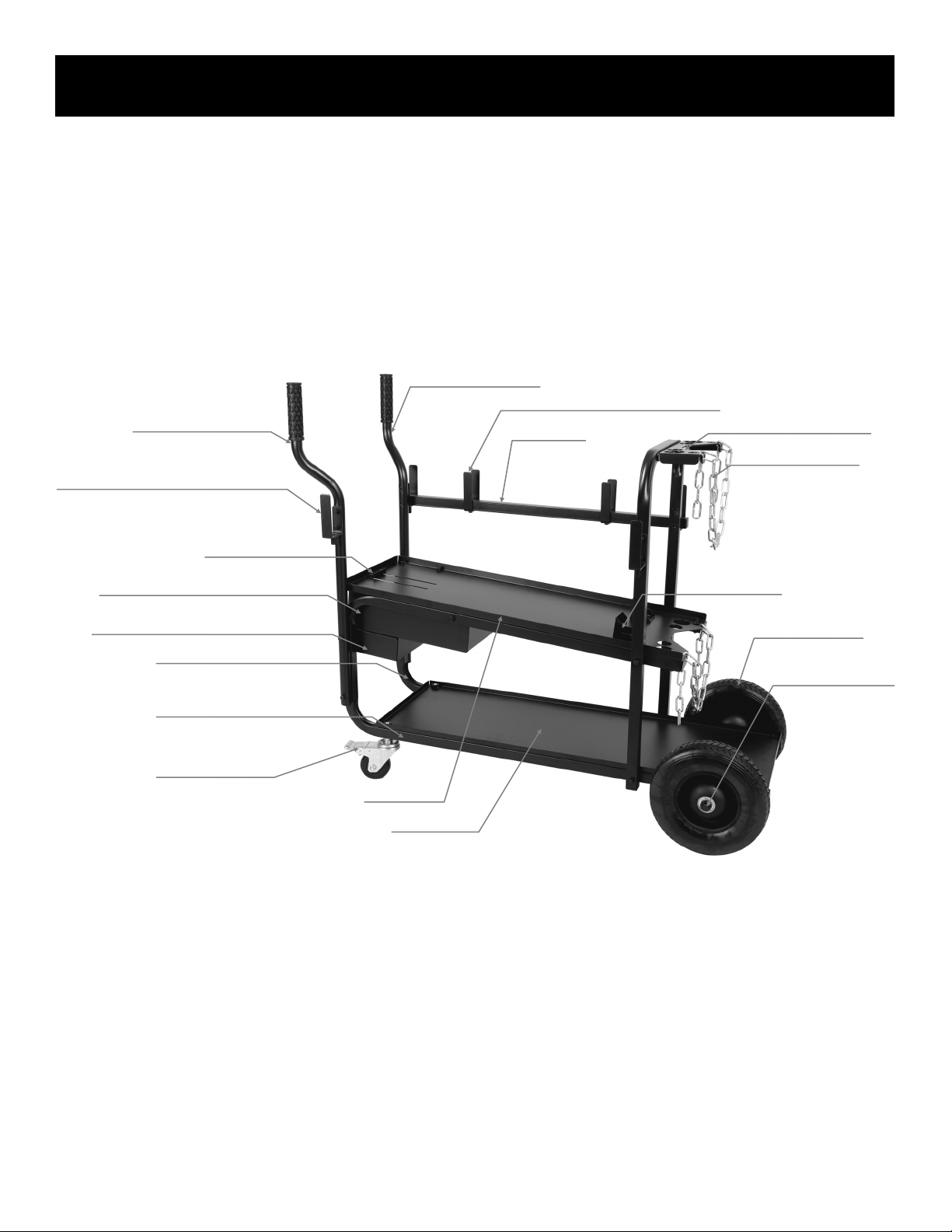
GENERAL DESCRIPTION AND ASSEMBLY.
This cart is designed to hold a wide variety of welders, and is
equipped with locking front casters to hold it in place so that it will
not roll when movement needs to be restricted. It is designed to
hold most welders, welder-cooler combinations and some plasma
cutters that reach the minimum size. Adjustable sliding stops and rear
capture tabs are used on this unit to provide a friction t for the weld-
er or welder/cooler combination. The adjustable stops allow a weld-
er/cooler length of 18.9” to 25” (480mm to 635mm). The width of the
cart allows a maximum width of 12” (307mm). The maximum height
of the combination of welder and cooler (measured when not in-
stalled on cart) should not exceed 34.1” (865mm), not including any
installed handle height. Maximum weight of cooler, cart, gas cylinder,
and accessories should not exceed 325 lbs. ( 147.4 kg).
During Assembly, be sure to assemble all parts nger tight only. Do
not begin to tighten any bolts until the cart is fully assembled. If you
tighten before the cart is assembled, some parts may not t properly
due to misalignment. Tighten everything lightly once, then retighten
fully.
This cart uses a captured nut (Rivet Nut) design. Be sure not to strip
these from over-tightening or cross threading. Do not tighten M6
bolts to more than 4.0 Newton-meters (35.4 inch-pounds) on nal
tightening.
NOVA 375-LF Welding Cart
IMPORTANT:
To obtain the longest service life out of this welding cart, periodic
maintenance will be required. Inspect all fasteners after 1 week of
use. Thereafter, it is recommended that you check for general tight-
ness and soundness of fasteners every 90 days of use. Additionally,
it is recommended that where appropriate, the wheels be lightly oiled
with machine oil periodically to maintain a smooth rolling mechanism.
Do not operate in mud or dirt. If the shop floor is dirty or full of metal
shavings and debris, periodically you should also inspect the wheels
for cuts and damage.
Discontinue use if any safety or structural part, particularly undercar-
riage parts becomes damaged or worn.
Move cart smoothly and slowly. Sudden jerking and sudden direction
change can cause cart failure due to excessive loading of components
due to dynamic changes when cart is near maximum capacity.
9
Specifications
Welding Cart Specifications
Model 375-LF (Long Frame)
Empty (Net) weight 53 lbs.
Gross (Maximum) weight 375 lbs.
Assembled dimensions 43.3”L x 18.9”W x 37.8”H
Maximum Cylinder Diameter Size/Type Up to 9”/300 Cu. Ft.
Number of gas cylinders supported One
Warranty 18 Months
WARNING!
RISK OF OVERTURN!
Improper use and operation of this welding cart may result in cart overturn and can result in serious injury and death!
• Do not overload this welding cart. Maximum permissible gross weight is 375 lbs. This includes cart weight.
• Do not modify or add to the cart as change in center of gravity may occur.
• This unit should only be operated on flat, even surfaces.
• Do not operate on slopes, or broken pavement or gravel.
• When negotiating ramps or inclines, only move the cart up and down the slope inline with the slope.
• Never move across a ramp or incline.
• Always use the wheel locks on the cart to prevent the cart from being accidentally moved when the cart is not being transported.
• Do not use wheel locks to hold the cart in place on a slope.
• Use both safety chains, if the cylinder height allows, to secure the gas cylinder.
• Use a ratchet strap to secure the welder and accessories to the cart.
• Always dismount the regulator and install the safety cap when moving the cart.
• Always dismount the regulator and install the safety cap when the welder is not being used.
10
Setup Guide
COMPONENT ID AND ASSEMBLY
Overview of Assembled Cart
Locking Casters
Right Steering Handle
Left Steering Handle
Accessory Hooks (Unequal Legs x4)
Adjustable Stop
Consumable Shelf with Plastic Box
Accessory Shelf/Foot Pedal Holder
Left Side Frame Support
Right Side Frame Support
Lower Deck
Accessory Hooks (Equal Legs x2)
Rear Stops (x2)
Cylinder Support Bracket
Safety Chains (x2)
Cross Bar
Upper Deck
Rear Wheels (x2)
Rear Axle Assembly
11
Setup Guide
COMPONENT ID AND ASSEMBLY
Exploded View and Parts List
Qty. Part Description/Size
2Screw M6 x 10mm for consumable box (amount may vary depending upon design changes)
8Bolt M6 x 10mm (amount may vary depending upon design changes)
10 Bolt M6 x 30mm (amount may vary depending upon design changes)
9Bolt M6 x 35mm (amount may vary depending upon design changes)
2Bolt M6 x 40mm (amount may vary depending upon design changes)
8Bolt M6 x 50mm (amount may vary depending upon design changes)
37 M6 Lock Washer (Split-Spring Type) (amount may vary depending upon design changes)
37 M6 Flat Washer (amount may vary depending upon model design changes)
2M12 Flat Washer (For Axle Assembly.)
6M6 Nuts
2E-Clips (For Rear Axle Assembly.)
1 Rear Axle
2Bushings (For Rear Axle Assembly.)
110” Wheels (For Rear Axle Assembly.)
2Front Locking Casters
2Safety Chain For Gas Cylinders
1Upper Cylinder Support Bracket
9Rear Frame Support (Equal Length Legs.)
1Left Steering Handle
1Left Side Frame Support (Unequal Length Legs. Rivet nut faces right when viewed from front.)
1Right Steering Handle
1Right Side Frame Support (Unequal Length Legs. Rivet nut faces left when viewed from front.)
1Lower Deck
1Upper Deck and Cylinder Support Bracket
1Front Adjustable Tab (To capture welder.)
2Rear Tabs (To capture welder.)
1Consumable Holder Shelf
1Plastic Consumable/Parts Box
1 Accessory/Foot Pedal Shelf
2Accessory Hooks (Unequal length legs.)
4Accessory Hooks (Equal length legs for support bar.)
1Cross Bar
12
Setup Guide
COMPONENT ID AND ASSEMBLY
Assembly of the Main Frame and Lower Deck
ASSEMBLING THE FRAME
Correctly assembling the frame is important to the integrity of the whole structure. Complete the following steps in order.
1. Locate the Left and Right Frame Assembly. Notice which direction the rivet nut is facing. The two sides with the rivet nuts should be facing each other.
2. Locate the lower deck.
3. Arrange the three pieces so that it appears similar to the drawing above.
4. Install two M6 x 30mm bolts along with the corresponding flat and split lock washers into the rear section of the lower deck as shown.
IMPORTANT! Always install the bolts with the flat washer facing the component part being assembled. The lock washer
will sit on top of the flat washer. The bolt will then be inserted through both. The lock washer will be sandwiched between
the bottom of the bolt and the flat washer. If this order is not maintained, the assembly could become loose.
13
Setup Guide
COMPONENT ID AND ASSEMBLY
Assembly of the Casters and Upper Deck
SECURING THE FRAME TO THE UPPER DECK AND INSTALLING THE CASTERS
Correctly assembling the frame is important to the integrity of the whole structure. Complete the following steps in order.
1. Locate the front locking casters.
2. Install Casters through the front frame holes. Depending upon the model, install the spacers provided (if any).
3. Lightly tighten the casters so that threads on the casters thread through the Rivet nuts on the lower deck pan. Continue to tighten the casters until the lower deck
is snug against both frame rails. NOTE: Casters should rotate freely around without striking the frame. If they strike the frame, install the spacers/bushings.
4. Locate the top deck.
5. Locate the rear locking tabs .
6. Install and secure the rear locking tabs to the upper deck using 2 short M6 x 10mm bolts, along with the M6 split washers, M6 flat washers and M6 nuts.
7. Install top pan using 4 long M6 x 35mm bolts, M6 split washers and M6 flat washer.
8. When assembled, the upper deck should slope down from the front to the rear of the cart. When fully assembled, this will tilt the welderso that the face will be
pointing slightly up for better viewing and access to the front welder controls. This slight amount of slope will not affect the operation of most welders and coolers.
IMPORTANT! Always install the bolts with the flat washer facing the component part being assembled. The lock washer
will sit on top of the flat washer. The bolt will then be inserted through both. The lock washer will be sandwiched between
the bottom of the bolt and the flat washer. If this order is not maintained, the assembly could become loose.
14
Setup Guide
COMPONENT ID AND ASSEMBLY
Assembly of the Axle and Wheels
INSTALLING THE AXLE AND WHEELS
Complete the following steps in order.
1. Locate the Axle, two rear wheels, two bushing/spacers, two M12 washers and two E clips.
2. Insert the Axle fully through both sides of the frame rails.
3. Install the two bushings on either side of the frame rails. Notice the details above so that the bushing is correctly oriented. The flange, or step should be turned to
the inside. If the bushings do not easily slide on, lightly sand the surface and end of the axle until the bushings slide all the way on.
4. Install the both wheels on the bushings as shown.
5. Install the both M12 washers over the axle (one for each side) and push them on until they seat up against the wheel.
6. Install E-Clips on both sides to capture and hold the entire assembly together. Use a pair of pliers to hold the E clips and slide them onto the groove in the axle if
it cannot be done by hand.
IMPORTANT! Always install the bolts with the flat washer facing the component part being assembled. The lock washer
will sit on top of the flat washer. The bolt will then be inserted through both. The lock washer will be sandwiched between
the bottom of the bolt and the flat washer. If this order is not maintained, the assembly could become loose.
15
Setup Guide
COMPONENT ID AND ASSEMBLY
Installing the Front Adjustable Tab
INSTALLING THE FRONT ADJUSTABLE TAB
While it is not 100% necessary to perform this step, particularly if the welder has a marginal t, it is highly advised to do so. Complete the following steps in order.
1. Locate the front locking tab. This will be used to secure the welder by friction to the cart.
2. Use two M6 x 10mm bolts, M6 washers, M6 split lock washers and M6 nuts, secure the locking tab to the slotted grooves in the upper deck as shown. For most
installations, the leg of the “L” shape should face forward so that the welder can sit flush against the tab. See illustration above.
3. When completed, the adjustable tab should slide up and down, along the length of the slot.
IMPORTANT! Always install the bolts with the flat washer facing the component part being assembled. The lock washer
will sit on top of the flat washer. The bolt will then be inserted through both. The lock washer will be sandwiched between
the bottom of the bolt and the flat washer. If this order is not maintained, the assembly could become loose.
16
Setup Guide
COMPONENT ID AND ASSEMBLY
Installing the Accessory and Consumable Shelves
INSTALLING THE CONSUMABLE AND ACCESSORY(FOOT PEDAL HOLDER) SHELVES
Complete the following steps in order.
1. Locate both the accessory shelf and the consumable shelf (and plastic box).
2. Install the accessory shelf using two M6 x 10mm and M6 x 40mm bolts as shown. Be sure to use the M6 split lock washers, M6 flat washers, and M6 flat wash-
ers. Note: These are the hex head bolts, not the Phillips head screws that are to be used in this location.
3. Install the consumable shelf below the accessory shelf. Engage the locking tabs of the consumable shelf with the slots located on the bottom of the accessory
shelf. Use the M6 x 10mm Phillips type screws (not bolts), M6 split lock washers, M6 flat washers and M6 nuts to secure the consumable shelf. Note: The con-
sumable box is not a necessary part of the structure. It may be omitted if desired or if more under-shelf space is required for the lower deck.
4. Slide the consumable box into the opening of the consumable shelf. (Not pictured.)
IMPORTANT! Always install the bolts with the flat washer facing the component part being assembled. The lock washer will sit
on top of the flat washer. The bolt will then be inserted through both. The lock washer will be sandwiched between the bottom of
the bolt and the flat washer. If this order is not maintained, the assembly could become loose.
17
Setup Guide
COMPONENT ID AND ASSEMBLY
Completing the Handle and Rear Support Assembly
COMPLETING THE HANDLES AND REAR SUPPORT ASSEMBLIES
Complete the following steps in order to complete the assembly.
1. Locate two unequal length accessory hooks, and the upper cylinder support.
2. Use three of the M6 x 35mm bolts, M6 flat washers, M6 split washers to assemble the cylinder bracket as shown .
3. Be sure to notice the direction of the bolts on the upper cylinder bracket. Make sure the bracket is assembled with the flat side up as depicted.
4. Locate and install the two remaining unequal length accessory hooks to the left and right steering handles using the four M6 x 30mm bolts, M6 flat washers, M6
split lock washers. Make sure that the accessory hooks are pointing out in the same general direction of the handle. When completed, the handles should point
out and forward. The hooks should point out.
IMPORTANT! Always install the bolts with the flat washer facing the component part being assembled. The lock washer will sit
on top of the flat washer. The bolt will then be inserted through both. The lock washer will be sandwiched between the bottom of
the bolt and the flat washer. If this order is not maintained, the assembly could become loose.
18
Setup Guide
COMPONENT ID AND ASSEMBLY
Installing the Handles and Rear Support Assembly
COMPLETING THE HANDLES AND REAR SUPPORT ASSEMBLIES
Complete the following steps in order to complete the assembly.
1. Install the front handles so that they curve of the handles are facing to the front and pointing outwards. Use four M6 x 50mm bolts, M6 flat washers, and M6 split
lock washers to secure the handles to the front of the cart via the vertical portion of the frame rails to complete the assembly as shown.
2. Make sure the handles face forward and curve outwards. The hooks should face out.
3. Similarly, install the completed rear support assembly to the rear of the cart so that it appears as shown. Use 4 M6x 50mm bolts, M6 flat washers, and split lock
washers to secure the rear support to the frame. If the bolt holes don’t line up completely, gently spread the frame by hand until the holes line up. The bolts
should go all the way through the rear support assembly and the main frame rails.
IMPORTANT! Always install the bolts with the flat washer facing the component part being assembled. The lock washer will sit
on top of the flat washer. The bolt will then be inserted through both. The lock washer will be sandwiched between the bottom of
the bolt and the flat washer. If this order is not maintained, the assembly could become loose.
19
Setup Guide
COMPONENT ID AND ASSEMBLY
Installing Cross Bar and Accessory Hooks
INSTALLING THE CROSS BAR AND ACCESSORY HOOKS
Complete the following steps in order to complete the assembly.
1. Install Equal length Accessory hooks onto the cross bar as shown using two M6 x 30mm bolts, M6 split washers and M6 flat washers.
2. Insert the dowel locating pins on the bottom of the cross bar into the cups made into the bottom of the accessory brackets. Push down rmly to seat the cross bar.
3. NOTE: The cross bar may be mounted to either side, depending on the type of welder and operator preference.
IMPORTANT! Always install the bolts with the flat washer facing the component part being assembled. The lock washer will sit
on top of the flat washer. The bolt will then be inserted through both. The lock washer will be sandwiched between the bottom of
the bolt and the flat washer. If this order is not maintained, the assembly could become loose.
20
Setup Guide
COMPONENT ID AND ASSEMBLY
Complete and Inspect the Assembly
COMPLETING THE ASSEMBLY
Complete the following steps in order to complete the assembly.
1. Once all parts have been assembled inspect the nal product for tment and proper connections as depicted above.
2. Tighten all M6 screws and bolts. Lightly tighten the bolts working from side to side, top to bottom. Then torque to no more than 4.0 Nm or 35.4 inch-pounds.
3. Check and tighten the front casters 1/8” turn after fully seated
4. Install the safety chains and consumable box as shown. The top shelf can be used for storage of the foot pedal or other accessories.
5. Always use both safety chains.
6. After one week check and re-torque all bolts and casters
7. Every 90 days, inspect and retorque the bolts and casters if necessary. Replace any bolts that become stretched or stripped.
8. If needed the cross bar may be repositioned, but it should not be left off completely. This is part of the structure and frame assembly.

This manual suits for next models

1

Popular Outdoor Cart manuals by other brands

Ravendo TW 1000 M user manual

Ravendo

Ravendo TW 1000 M user manual

Hendi 8106 Series User instructions

Hendi

Hendi 8106 Series User instructions

Safco 5201 Assembly instructions

Safco

Safco 5201 Assembly instructions

Westfalia 14 14 99 instruction manual

Westfalia

Westfalia 14 14 99 instruction manual

ALCO RocknRoller Multi-Cart owner's manual

ALCO

ALCO RocknRoller Multi-Cart owner's manual

Fantom PROCART 330 Assembly manual

Fantom

Fantom PROCART 330 Assembly manual

Amazon B073P2LH2V manual

Amazon

Amazon B073P2LH2V manual

Toyota Prius C 2011 owner's manual

Toyota

Toyota Prius C 2011 owner's manual

Mocka Block Trolley Assembly instructions

Mocka

Mocka Block Trolley Assembly instructions

Makita DCU603 instruction manual

Makita

Makita DCU603 instruction manual

DOMPEL CARRINHO VIENA instruction manual

DOMPEL

DOMPEL CARRINHO VIENA instruction manual

Rx Systems V2 Refurbish Manual

Rx Systems

Rx Systems V2 Refurbish Manual

Seville Classics airLIFT OFF42630 Quick assembly instructions

Seville Classics

Seville Classics airLIFT OFF42630 Quick assembly instructions

DOMPEL MULTIUSO instruction manual

DOMPEL

DOMPEL MULTIUSO instruction manual

Copernicus BB005 Assembly guide

Copernicus

Copernicus BB005 Assembly guide

Sunjoy D-GW088PWD Assembly instructions

Sunjoy

Sunjoy D-GW088PWD Assembly instructions

Parker 10MFP manual

Parker

Parker 10MFP manual

Diamondback Ranger Roof owner's manual

Diamondback

Diamondback Ranger Roof owner's manual

manuals.online logo
manuals.online logoBrands
  • About & Mission
  • Contact us
  • Privacy Policy
  • Terms and Conditions

Copyright 2025 Manuals.Online. All Rights Reserved.