Graco LineDriver ES Use and care manual

Operation, Repair, Parts
LineDriver™ES 3A6623D
EN
For the propulsion of line striping and removal equipment. Not approved for use in
explosive atmospheres or hazardous locations. For professional use only.
Models: 25N555, 25N556
10 mph (16 kph) Maximum Operating Speed
Important Safety Instructions
Read all warnings and instructions in this manual and in related LineLazer,
GrindLazer and ThermoLazer manuals before using the equipment. Save
these instructions.
Related Manuals:
710-0138 Delta-Q Battery Charger
3A6720 Hitch Receiver Kit
LineDriver ES
Model Series Cord Adapter
--- 25N555 B North America
25N556 B
North America
Australia
CEE 7/7
Denmark
Italy
Switzerland
United Kingdom
Use only genuine Graco replacement parts.
The use of non-Graco replacement parts may void warranty.

23A6623D
Contents
Warnings . . . . . . . . . . . . . . . . . . . . . . . . . . . . . . . . . 3
Component Identification . . . . . . . . . . . . . . . . . . . . 5
Setup . . . . . . . . . . . . . . . . . . . . . . . . . . . . . . . . . . . . . 6
12V Auxiliary Ports . . . . . . . . . . . . . . . . . . . . . . . 6
Startup . . . . . . . . . . . . . . . . . . . . . . . . . . . . . . . . . . . 7
Know Your Controls . . . . . . . . . . . . . . . . . . . . . . 7
Daily Inspections . . . . . . . . . . . . . . . . . . . . . . . . . 8
Operation . . . . . . . . . . . . . . . . . . . . . . . . . . . . . . . . . 9
Differences in Operation . . . . . . . . . . . . . . . . . . . 9
How to Operate . . . . . . . . . . . . . . . . . . . . . . . . . . 9
Operating on Inclines . . . . . . . . . . . . . . . . . . . . 10
Trailer Loading & Unloading . . . . . . . . . . . . . . . 10
Charging the Batteries . . . . . . . . . . . . . . . . . . . 11
Maintenance . . . . . . . . . . . . . . . . . . . . . . . . . . . . . . 13
Parking/Emergency Brake Adjustment or
Replacement . . . . . . . . . . . . . . . . . . . . . . . 13
Throttle Linkage Adjustment . . . . . . . . . . . . . . . 14
Coupler Adjustment . . . . . . . . . . . . . . . . . . . . . 15
Accelerator Calibration (Using Kit 25N880) . . . 15
Transaxle Service . . . . . . . . . . . . . . . . . . . . . . . 17
Repair . . . . . . . . . . . . . . . . . . . . . . . . . . . . . . . . . . . 18
Battery Pack Replacement . . . . . . . . . . . . . . . . 18
Battery Disposal . . . . . . . . . . . . . . . . . . . . . . . . 18
Transaxle Replacement . . . . . . . . . . . . . . . . . . . 19
Traction Motor Replacement . . . . . . . . . . . . . . . 19
Motor Controller Replacement . . . . . . . . . . . . . . 19
Troubleshooting - LineDriver . . . . . . . . . . . . . . . . 20
Troubleshooting - Motor Controller . . . . . . . . . . . 21
Parts Drawing . . . . . . . . . . . . . . . . . . . . . . . . . . . . . 26
Parts Drawing . . . . . . . . . . . . . . . . . . . . . . . . . . . . . 27
Parts Drawing - Detail Views . . . . . . . . . . . . . . . . . 28
Parts Drawing . . . . . . . . . . . . . . . . . . . . . . . . . . . . . 29
Parts List . . . . . . . . . . . . . . . . . . . . . . . . . . . . . . . . . 30
Wiring Diagram - Harness 25N661 . . . . . . . . . . . . 32
Wiring Diagram . . . . . . . . . . . . . . . . . . . . . . . . . . . 33
Wiring Diagram - Harness 25E406 . . . . . . . . . . . . 34
Technical Specifications . . . . . . . . . . . . . . . . . . . . 35
Graco Standard Warranty . . . . . . . . . . . . . . . . . . . 36
Graco Information . . . . . . . . . . . . . . . . . . . . . . . . . 36

Warnings
3A6623D 3
Warnings
The following warnings are for the setup, use, grounding, maintenance, and repair of this equipment. The exclamation
point symbol alerts you to a general warning and the hazard symbols refer to procedure-specific risks. When these sym-
bols appear in the body of this manual or on warning labels, refer back to these Warnings. Product-specific hazard sym-
bols and warnings not covered in this section may appear throughout the body of this manual where applicable.
MOVING VEHICLE HAZARD
Careless and reckless behavior causes accidents. Falling from vehicle, running into people or objects, or being
struck by other vehicles may result in serious injury or death.
•
Do not operate unless attached to line striping or line removal equipment.
•
Do not step on Direction/Speed Pedals.
•
Make turns slowly. Do not make turns greater than 45°.
•
Loss of traction may occur going downhill.
•
Do not operate on inclines greater than 7.5°.
•
Do not carry passengers.
•
Do not tow.
•
Use with line striping or line removal equipment only.
•
Use appropriate traffic control in all traffic areas. Refer to manual on Uniform Traffic Control Devices (MUTCD), U.S.
Department of Transportation, Federal Highway Administration or local highway and transportation regulations.
TRAFFIC HAZARD
Vehicle strikes may result in serious injury or death.
• Do not operate in traffic.
• Use traffic control.
ELECTRIC SHOCK HAZARD
This equipment must be grounded. Improper grounding, setup, or usage of the system can cause electric
shock.
• Turn off and disconnect power cord before servicing equipment.
• Connect only to grounded electrical outlets.
• Use only 3-wire extension cords.
• Ensure ground prongs are intact on power and extension cords.
• Do not expose to rain. Store indoors.
EQUIPMENT MISUSE HAZARD
Misuse can cause death or serious injury.
• Do not operate the unit when fatigued or under the influence of drugs or alcohol.
• Check equipment daily. Repair or replace worn or damaged parts immediately with genuine manufacturer’s
replacement parts only.
• Do not alter or modify equipment. Alterations or modifications may void agency approvals and create safety
hazards.
• Make sure all equipment is rated and approved for the environment in which you are using it.
• Use equipment only for its intended purpose. Call your distributor for information.
• Keep children and animals away from work area.
• Comply with all applicable safety regulations.
BURN HAZARD
Equipment surfaces and fluid that is heated can become very hot during operation. To avoid severe burns:
• Do not touch hot fluid or equipment.

Warnings
43A6623D
BATTERY HAZARD
Lead-acid batteries produce explosive gases and contain sulfuric acid that can cause severe burns. To avoid
sparks and injury when handling or working with a lead-acid battery:
• Only use the battery type specified for use with the equipment. See Technical Data.
• Read and follow the battery manufacturer’s warnings.
• Exercise caution when working with metallic tools or conductors to prevent short circuits and sparks.
• Keep all sparks, flames, and cigarettes away from batteries.
• Always wear protective eyewear and protective equipment for face, hands, and body.
• If you have direct contact with battery fluid, flush with water and consult a physician immediately.
• Installation and maintenance must be performed by knowledgeable personnel only.
GROUNDING
This product must be grounded. In the event of an electrical short circuit, grounding reduces the risk of elec-
tric shock by providing an escape wire for the electric current. This product is equipped with a cord having a
grounding wire with an appropriate grounding plug. The plug must be plugged into an outlet that is properly
installed and grounded in accordance with all local codes and ordinances.
• Improper installation of the grounding plug is able to result in a risk of electric shock.
• When repair or replacement of the cord or plug is required, do not connect the grounding wire to either flat
blade terminal.
• The wire with insulation having an outer surface that is green with or without yellow stripes is the grounding
wire.
• Check with a qualified electrician or serviceman when the grounding instructions are not completely under-
stood, or when in doubt as to whether the product is properly grounded.
• Do not modify the plug provided; if it does not fit the outlet, have the proper outlet installed by a qualified
electrician.
• This product is for use on a nominal 120V or 230V circuit and has a grounding plug similar to the plugs illus-
trated below.
• Only connect the product to an outlet having the same configuration as the plug.
• Do not use an adapter with this product.
PERSONAL PROTECTIVE EQUIPMENT
Wear appropriate protective equipment when in the work area to help prevent serious injury, including eye
injury, hearing loss, inhalation of toxic fumes, and burns. Protective equipment includes but is not limited to:
• Protective eyewear, and hearing protection.
• Respirators, protective clothing, and gloves as recommended by the fluid and solvent manufacturer.
120V US 230V

Component Identification
3A6623D 5
Component Identification
1 Headlight
2 Direction/Speed Pedals
3 Step Plate
4Hitch
5 Coupler
6 Safety Pin Location
7 Handle Open
8 Handle Locked
9 Parking/Emergency Brake
10 Tool Tray
11 Seat Adjustment
12 Operator Seat
13 Serial ID
14 Power Switch
15 Speed Switch
16 ExactMil™Speed Control
17 Voltage Meter
18 12V Aux. Power
19 Light Socket
20 Motor Controller Diagnostic Light
21 Battery Charger
22 Seat Lid
23 Buzzer
24 Seat Cover
25 Seat Interlock Switch

Setup
63A6623D
Setup
1. Install supplied ramp onto pallet.
2. Connect Hitch Receiver to line striping or line
removal equipment - Hitch Receiver Kit 25N787;
Manual 3A6720.
3. Install LineDriver Coupler to striper or grinder hitch
ball.
4. Latch Coupler to locked position (M).
NOTE: If Coupler is too tight to latch or is loose after
latching, Coupler needs adjustment. Refer to Coupler
Adjustment, page 15.
5. Insert safety pin in latch
6. Adjust seat forward/backward with lever below seat.
7. Adjust height of pedals to desired position by
removing/replacing bolts (Y).
8. Loosen two bolts (C) on topside of pedals. Rotate
pedal to desired position. Tighten bolts.
12V Auxiliary Ports
12V auxiliary power ports are provided to power acces-
sories.
ti11087a
ti10936a
M
NOTICE
12V auxiliary ports must be used to power accessories.
Battery damage can result if other means are used to
power accessories.
ti11086a
ti11085a

Startup
3A6623D 7
Startup
Know Your Controls
Direction/Speed Pedals
The Direction/Speed Pedals drive the LineDriver forward
and in reverse. Switching from forward to reverse creates
a braking action. When both feet are removed from the
pedals, the LineDriver stops. Use one or both feet to
operate the pedals.
Parking/Emergency Brake
The Parking/Emergency Brake stops the machine in an
emergency and prevents it from rolling when parked. To
engage the Parking/Emergency Brake, press brake
pedal firmly until it latches. To release, press the lower
edge of the brake pedal.
Speed Switch
ExactMil™(Speed Control) Mode
ExactMil Mode ensures a consistent paint thickness by
holding the speed steady. To enable ExactMil mode:
1. Stop moving. Turn speed control knob all the way
counterclockwise.
2. Set Speed Switch to ExactMil position.
3. Depress foot pedal to go forward. Adjust speed con-
trol knob to desired speed setting.
NOTE: ExactMil speed control is only active when mov-
ing forward. Reverse speed is not impacted. ExactMil
speed control limits the maximum speed that can be
obtained with the pedal.
To disable ExactMil Mode:
• Return Speed Switch to center position.
Full Speed Mode
Set Speed Switch to the center position. This allows
a forward speed of 10 mph (16 kph) and a reverse speed
of 7 mph (11 kph).

Startup
83A6623D
Incline/ECO Mode
Incline/ECO Mode is the recommended default mode for
all operations. It is helpful when greater control is
needed such as during loading or unloading and in con-
gested areas. Incline/ECO mode should be used when
operating on inclines. It also extends battery life. To
enable Incline/ECO mode:
• Set Speed Switch to Incline/ECO position.
NOTE: Incline/ECO Mode limits forward speed to 5.5
mph (9 kph) and reverse speed to 4 mph (6 kph).
To disable Incline/ECO Mode:
• Return Speed Switch to center position.
Buzzer
A buzzer will sound to indicate different operating
conditions.
Daily Inspections
Perform the following inspections each day before using
the LineDriver ES.
1. Check battery charge level. Charge if not fully
charged.
2. Inspect Coupler for excess movement. Adjust if
needed. See Coupler Adjustment, page 15.
Replace Coupler when it is no longer adjustable.
3. Check function of the Seat Interlock Switch. The
Seat Interlock Switch stops the ES Driver when the
operator leaves the seat, and disables the Direc-
tion/Speed Pedals.
a. With the Parking/Emergency Brake ON, move
the Power Switch to the ON position while
standing next to the LineDriver ES.
b. Gently tap the Direction/Speed Pedals. The
LineDriver ES should not attempt to travel.
c. Sit on the seat and gently tap the Direc-
tion/Speed Pedals. The unit should attempt to
travel.
d. Service the Seat Interlock Switch if the Line-
Driver does not respond as described in steps b
and c above.
4. Test Parking/Emergency Brake function and adjust-
ment.
a. Choose a flat open area. Accelerate unit to 3
mph (5 kph).
b. Cause the LineDriver ES to roll freely (free-
wheel) by moving the Power Switch to the OFF
position.
c. Stop unit by applying Parking/Emergency
Brake. To adjust brakes, see Parking/Emer-
gency Brake Adjustment or Replacement,
page 13.
Single tone, about one
second long, after
turning the Power Switch
ON.
Direction/Speed control
pedals now active.
Repeating tone, about
every second.
Batteries are deeply
discharged. See
Charging the Batteries,
page 11.
Continuous tone while
traveling faster than 6.5
mph (10 kph).
Reduced braking available
from Direction/Speed
Pedals. See warning in
Extended Braking
Distance, page 10.

Operation
3A6623D 9
Operation
Differences in Operation
The LineDriver ES operates differently than a gasoline
powered LineDriver.
1. LineDriver ES rolls freely, especially on inclines,
when the power is off. Set Parking/Emergency
Brake before turning off.
2. Turn power on before releasing Parking/Emergency
Brake.
3. Performance drops when the battery charge
becomes low. When there is about one hour of run-
time remaining, the Voltage Meter begins to flash.
When the batteries are deeply discharged and the
LineDriver ES is about to shut down, the buzzer
sounds about once per second.
4. The response of the Direction/Speed pedals is
softer. Learn this softer response before operating
on a job site.
How to Operate
1. Sit on seat to actuate Seat Interlock Switch. Ensure
Direction/Speed Pedals are not depressed.
2. Turn Power Switch ON. Buzzer will sound in a few
seconds, indicating that the Direction/Speed Pedals
are now active.
3. Disengage Parking/Emergency Brake on LineDriver
and any brakes on attached equipment.
4. Squeeze hand control to release caster wheel of
attached equipment.
NOTE: LineDriver motion is forward and reverse. Turns
are made with the striper or grinder.
5. Push striper or grinder handle bars to begin desired
turn.
6. Move Direction/Speed pedals to drive the Line-
Driver, as shown below. Switching from forward to
reverse creates a braking action.
NOTE: LineDriver stops when both feet are removed
from pedals.
ti10937a
FREEWHEEL HAZARD
Turning the Power Switch OFF will result in loss of
drive power. Loss of drive power causes LineDriver to
freewheel, which allows it to roll freely.
• Do not turn Power Switch OFF while LineDriver is in
motion.
• If loss of drive power occurs while LineDriver is in
motion, use the Parking/Emergency Brake to bring
LineDriver to a stop.
• Always engage Parking/Emergency Brake before
turning Power Switch OFF or standing up from
seat.
ti10935a

Operation
10 3A6623D
7. Engage Parking/Emergency Brake when not oper-
ating LineDriver. This prevents rolling when on an
incline.
Operating on Inclines
Extended Braking Distance
Operating on inclines results in extended braking dis-
tances.
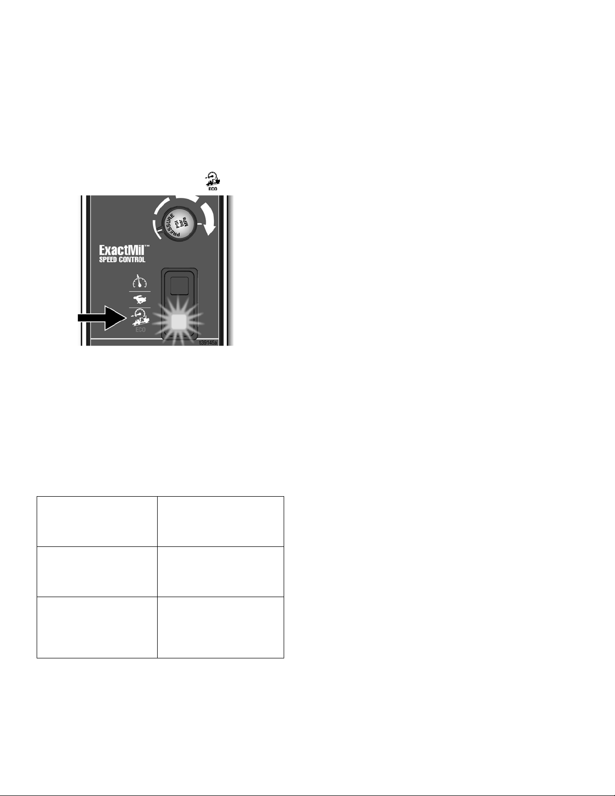
1. Select Incline/ECO mode on Speed Switch when
operating on inclines.
2. Be prepared to use the Parking/Emergency Brake
when operating on inclines.
NOTE: Do not operate on inclines greater than 7.5
°
(13%).
Starting and Stopping on an Incline
1. Engage the Parking/Emergency Brake before turn-
ing the Power Switch to OFF when parking on an
incline.
2. Turn the Power Switch to ON, and allow the
machine to initialize before releasing the Park-
ing/Emergency Brake when starting on an incline.
Trailer Loading & Unloading
NOTE: LineDriver ES rolls freely, especially on inclines,
when the power is off. Set Parking/Emergency Brake
before turning off. Turn power on before releasing Park-
ing/Emergency Brake.
1. Always keep LineDriver connected to striper or
grinder.
2. Use a level surface to load and unload. Leave suffi-
cient space behind ramps.
3. Use loading ramps of sufficient length and capable
of handling weight of unit and operator.
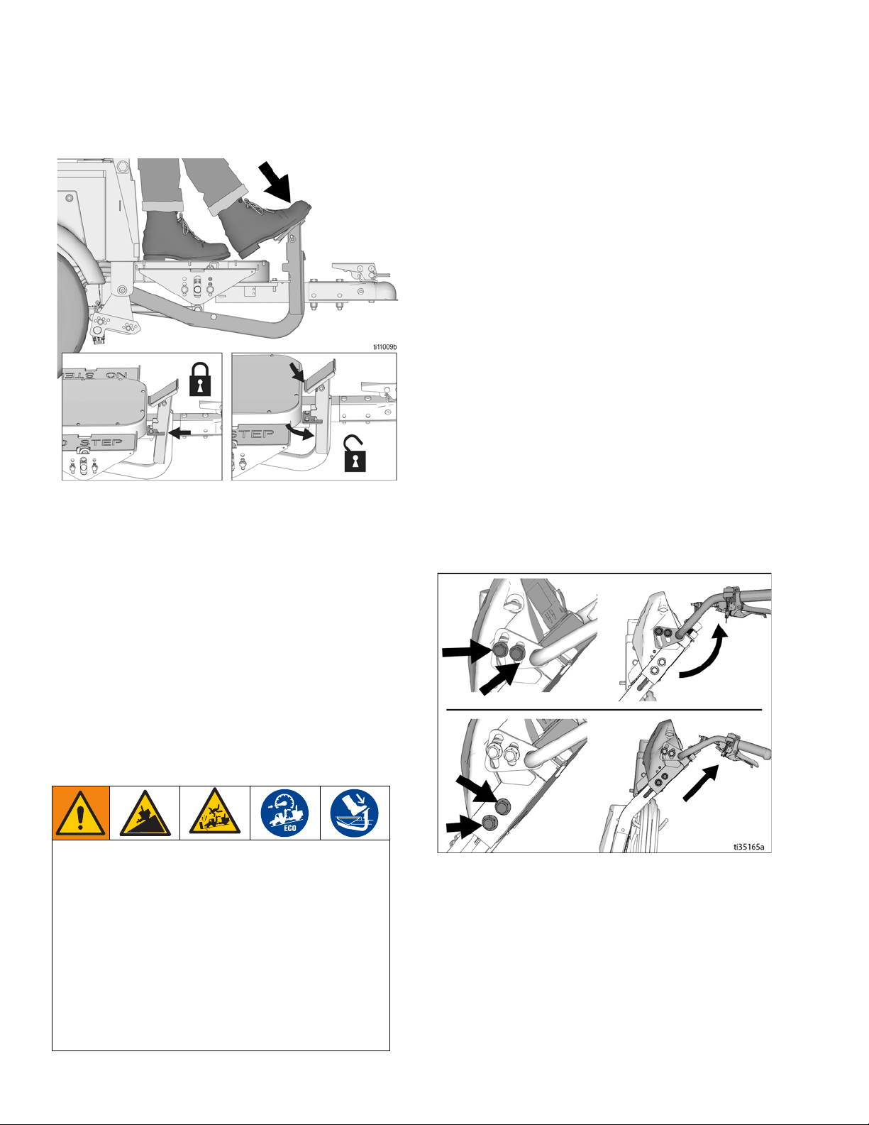
4. Adjust striper or grinder handlebar to highest posi-
tion. Slide seat back as far as possible.
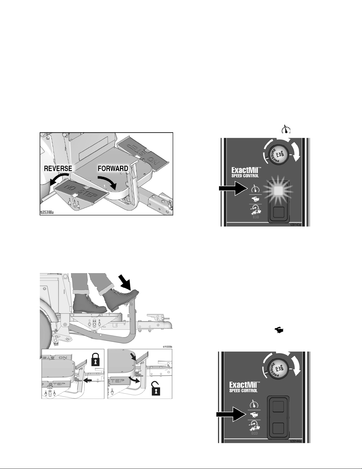
5. Use right foot to engage Parking/Emergency Brake.
Use left foot to control speed. Use ECO Mode to
limit speed.
6. Slowly drive straight up/down ramps (do not drive at
an angle).
7. Keep a firm grip on handlebars as the ramp is nego-
tiated.
NOTE: Striper or grinder handlebars swing up/down as
the ramp is engaged/disengaged. Keep legs clear.
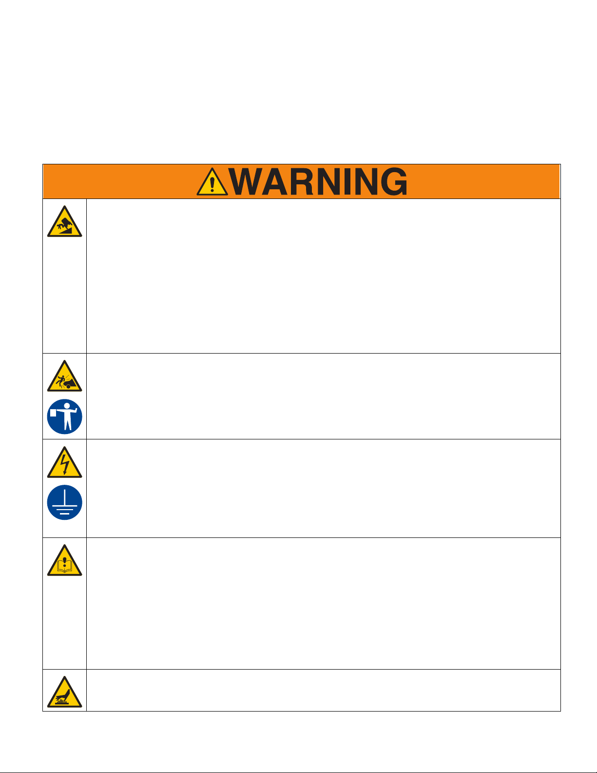
REDUCED BRAKING HAZARD
The braking from the Direction/Speed pedals can be
significantly reduced when going down inclines at
speeds over 6.5 mph (10 kph). This reduced braking
results in longer braking distance than normal, which
could lead to an accident.
A continuous buzzer alarm will sound when this
reduced braking condition occurs. If this alarm
sounds, apply the Parking/Emergency Brake to slow
down. Failure to do so could result in serious injury.
• Do not drive in a manner that causes this alarm to
sound.

Operation
3A6623D 11
Charging the Batteries
The charger may be used any time the LineDriver is not
being used. When the batteries are fully charged, the
charger automatically stops. If the LineDriver is stored
for an extended period, the batteries may self-discharge
enough for the charger to automatically recharge the
batteries. For optimum battery life, always leave the
charger plugged in.
Batteries are fully charged when leaving the factory.
Due to self-discharging of the battery, charge battery
before first use. It takes ~18 hours to charge a fully
depleted battery, and ~8 hours to charge the battery 3/4
full.
NOTE: Battery life depends on the depth of discharge
per cycle. A battery that is discharged to 50% depth will
get over twice as many cycles in its life compared to it
being discharged to 100% depth each cycle.
1. Place unit in dry, well-ventilated area and away from
flammable or combustible materials, including
paints and solvents.
2. Position the driver so the wheels are on a true
grounded surface, not on pavement.
3. Ensure Power Switch is in OFF position.
4. Plug charging cord into charging port on the unit.
Connect an extension cord, per charger manual, to
the charging cord and plug it into wall power.
Always use an outlet that is properly installed and
grounded in accordance with all local codes and ordi-
nances.
Do not modify the plug provided; if it does not fit the
outlet, have the proper outlet installed by a qualified
electrician.
Power Requirements
• All models use the same battery charger. Refer to
Technical Specifications, page 35, for power
requirements.
Replace and charge battery only in well-ventilated
area and away from flammable or combustible mate-
rials, including paints and solvents. The charger may
become hot while charging. Do not touch. Refer to
Charger Manual for additional information.
NOTICE
Lead acid batteries can self-discharge in as little as 3
months depending on storage temperatures. The hotter
the storage temperature, the faster the self-discharge
occurs. To prevent damage to the battery, it is import-
ant to keep the battery in a charged state.
This equipment must be grounded to reduce the risk
of static sparking and electric shock. An electric
shock or static spark can cause fumes to ignite or
explode. An improper ground can cause electric
shock. A good ground provides an escape wire for
the electric current.

Operation
12 3A6623D
5. The Charging Output Indicator means that the char-
ger output is active.
6. When power is connected, charger will immediately
begin charging.
NOTE: Battery will charge to ~30 volts while charging
and then it will come back down to ~27 volts after fully
charging.
NOTE: The Charge Display may show codes to indicate
different conditions. Refer to charger manual for addi-
tional information.
• ‘F’ codes meaning that an internal fault condition
has caused charging to stop.
• ‘E’ codes meaning that an external error condition
has caused charging to stop.
7. When battery charge indicator is solid green, the
charge is complete.
DISPLAY
CHARGING
OUTPUT
INICATOR
USB PORT
STATE OF
CHARGE
INDICATOR
FAULT
INDICATOR
ti35137a

Maintenance
3A6623D 13
Maintenance
Parking/Emergency Brake
Adjustment or Replacement
1. Block tires so LineDriver will not move. Release
Parking/Emergency Brake.
2. Ensure Power Switch is in OFF position.
3. Inflate tires to operating pressure per tire sidewall.
Remove two bolts securing brake rod.
4. Select a hole pattern that positions the brake rod 1/8
to 1/4 in. from the tire.
5. Install two bolts and secure brake rod. Repeat for
second tire.
NOTE: Brake rods are not interchangeable from side to
side. Model shown in the graphic above is the right side
version.

Maintenance
14 3A6623D
Throttle Linkage Adjustment

Maintenance
3A6623D 15
Coupler Adjustment
A Coupler too tight or too loose needs to be adjusted.
Before adjusting, check ball and Coupler for wear.
Replace entire Coupler if unable to tighten it.
Ensure Power Switch is in OFF position.

Maintenance
16 3A6623D
Accelerator Calibration (Using Kit 25N880)
1. Turn power OFF. Engage Parking/Emergency
Brake.
2. Slowly raise hitch Coupler until LineDriver rests on
rear bumper.
3. Remove accelerator from LineDriver.
4. Connect calibration cable per illustration. Use a Dig-
ital Multi-Meter to measure volts DC.
5. Mount accelerator to calibration plate and plate to
pedal. This makes it easier to torque fasteners.
6. Ensure nothing is on the operator’s seat so the Seat
Interlock Switch prevents wheel movement. Turn
power ON.
7. Loosen adjustment fastener and set neutral position
voltage to 2.45 ± .05 volts. Use calibration plate to
hold accelerator in this position. Torque adjustment
fastener to 90-100 in-lbs.
8. Rotate accelerator arm back and forth, then return it
to neutral position. Re-adjust voltage if necessary.
Turn power OFF.
9. Install accelerator onto LineDriver. When connect-
ing linkage, adjust tie rod end so no pressure is
needed to align parts. Otherwise the LineDriver will
creep.
10. LineDriver may creep forward or reverse when
turned on. As a precaution, jack unit up and use jack
stands to support it (two under the frame in the rear
and one under the Coupler).
11. Connect the LineDriver to a striper or grinder, sit on
the seat and turn on. If wheels do not turn (with no
pressure on speed pedals), calibration is complete.
If they do turn, follow Throttle Linkage Adjust-
ment, page 14.

Maintenance
3A6623D 17
Transaxle Service
Check Oil Level (Annually)
1. Turn power OFF. Engage Parking/Emergency
Brake.
2. Slowly raise hitch Coupler until LineDriver rests on
rear bumper.
3. Remove fill plug from transaxle cover.
4. Slowly lower hitch Coupler. Oil will begin to flow out
of transaxle when hitch Coupler is lowered to 10.5 -
12.5” from the floor. Add or remove oil as needed.
5. Reinstall plug.
Change Oil (recommended every 3 years)
1. Turn power OFF. Engage Parking/Emergency
Brake.
2. Slowly raise hitch Coupler until LineDriver rests on
rear bumper.
3. Place pan under transaxle cover. Remove screws
and cover.
NOTE: Sealant may hold cover on. If necessary, pry
cover off.
4. Allow oil to drain completely. Follow local ordi-
nances and regulations for disposal.
5. Clean cover and housing where sealant is used.
Apply new sealant (recommended is RTV silicone).
6. Reinstall cover with screws.
7. Remove drain plug. Fill with 22 oz. of Mobilfluid™
424.
8. Check oil level per above. Reinstall plug.
9. Check for oil leaks. Fix if necessary.

Repair
18 3A6623D
Repair
Battery Pack Replacement
NOTE: Prior to replacing batteries, use Troubleshoot-
ing - LineDriver, page 20, to determine if the batteries
are the cause of the problem. Also, use a battery load
tester to confirm the batteries need replacement. Always
replace all four batteries.
1. Turn Power Switch OFF. Turn lights OFF. Discon-
nect 12V accessories.
2. Remove Tool Tray.
3. Remove rear screws of Seat Lid.
4. Pivot Operator Seat forward slowly.
5. Remove battery cables.
6. Remove battery holders. Remove batteries and
recycle according to below.
7. Install new batteries in orientation shown. Install
holders and cables.
8. Reinstall seat and Tool Tray.
9. Charge batteries. See
Charging the Batteries
, page
11.
Battery Disposal
Do not place batteries in the trash. Recycle batteries
according to local regulations.

Repair
3A6623D 19
Transaxle Replacement
1. Turn power OFF.
2. Remove rear screws of Seat Lid. Pivot seat forward
slowly.
3. Disconnect battery cables to motor controller.
4. Jack unit up and use jack stands to support unit (two
jacks at the rear and one jack in the front). Raise
wheels about 2 inches off the floor, leaving enough
room to pull the transaxle out.
5. Remove wheels.
6. Remove motor cover.
7. Disconnect wires attached to motor.
8. Place a support under motor and remove transaxle.
9. Place new transaxle under unit. Lay motor wires on
transaxle.
10. Bolt new transaxle to frame.
11. Connect wires to motor. Take care when attaching
the three large cables to prevent damage to the
plastic terminal block on the motor.
12. Install motor cover.
13. Install wheels.
14. Lower unit to the floor and reconnect the battery
cables.
15. Reinstall Operator Seat.
Traction Motor Replacement
Follow Transaxle Replacement, page 19.
Motor Controller Replacement
1. Turn power OFF.
2. Remove rear screws of Seat Lid. Pivot seat forward
slowly.
3. Disconnect battery cables to motor controller. Tape
over terminals to prevent accidental contact.
4. Remove Seat Cover to expose motor controller.
5. Disconnect wires from motor controller.
6. Remove nuts holding motor controller in place.
7. Install new motor controller.
8. Connect wires to new motor controller. Be sure 35
pin connector latches.
9. Install Seat Cover.
10. Reconnect battery cables. Pivot seat back and rein-
stall rear screws of Seat Lid.
11. LineDriver may creep forward or reverse when
turned on. As a precaution, jack unit up and use jack
stands to support it (two under the frame in the rear
and one under the Coupler).
12. Sit on the seat and turn on. If wheels turn with no
pressure on speed pedals, follow the Accelerator
Calibration Procedure, page 16.

Troubleshooting - LineDriver
20 3A6623D
Troubleshooting - LineDriver
PROBLEM CAUSE SOLUTION
Parking/Emergency Brake does not keep Line-
Driver from moving
Parking Brake needs adjustment Adjust Parking Brake
Tire pressure too low Adjust pressure per tire sidewall
LineDriver creeps in forward or reverse direction Throttle linkage too long or too short Adjust throttle linkage
Head light does not turn on Connections Repair connections
LED Replace light
Open 10 amp fuse Address cause of high current Replace fuse
Switch Replace switch
LineDriver does not move forward or reverse -
Voltage Meter ON
Batteries discharged Charge batteries at least 2 hours
Seat Interlock Switch Sit on seat
Speed pedals engaged while turning unit on Disengage pedals then turn unit on
Speed pedals engaged for 15 seconds with no
LineDriver movement
Turn Power Switch OFF then back ON to reset
motor controller
Motor Controller fault Follow Troubleshooting - Motor Controller
instructions, page 21
LineDriver does not move forward or reverse -
Voltage Meter OFF
Batteries discharged Charge batteries at least 2 hours
Power Switch OFF Pull knob up
Open 20 amp fuse Address cause of high current Replace fuse
Open 300 amp fuse Address cause of high current Replace fuse
LineDriver only moves slowly Parking/Emergency Brake engaged Disengage Parking/Emergency Brake
Batteries discharged Charge batteries at least 2 hours
ExactMil™Speed Control ON Increase speed setting or turn OFF
ECO Mode ON Turn OFF
Motor Controller fault Follow Troubleshooting - Motor Controller
instructions, page 21
Battery charger not charging Batteries already charged Charge batteries after voltage drops below
25.0V
Charger has error or fault code Clear code. See charger manual
Batteries discharge within 6 hours of usage
(even when charged overnight)
Parking/Emergency Brake engaged Disengage brake while operating
Wheels rubbing Clear material away from wheels
Batteries unable to hold charge Replace all four batteries
Charger has error or fault code Clear code. See charger manual
Hitch Coupler too tight to latch or too loose after
latching
LineDriver hitch Coupler too loose or tight on
ball
Adjust Coupler
Voltmeter flashes ON/OFF Batteries discharged and less than one hour of
runtime left
Charge batteries at least 2 hours
Buzzer sounds about once per second Batteries deeply discharged and system about
to shut off
Charge batteries at least 2 hours
Buzzer sounds continuously when traveling
over 6.5 mph (10 kph).
Braking from Direction/Speed Control pedals
is significantly reduced.
Slow down. Apply Parking/Emergency Brake
as needed.
This manual suits for next models
2
Table of contents
Other Graco Outdoor Cart manuals
Popular Outdoor Cart manuals by other brands

Town Food Service Equipment
Town Food Service Equipment YORK 224800 owner's manual

Techly
Techly ICA-TR3390 manual

Anthro
Anthro TECHNOLOGY FURNITUR SEC24 Series Assembly instructions

DECK DOLLY
DECK DOLLY AutoConnect JD 7 Series Assembly instructions

The Handy
The Handy THTPDC Operator's manual & parts list

Vestil
Vestil PLDL-Series instruction manual