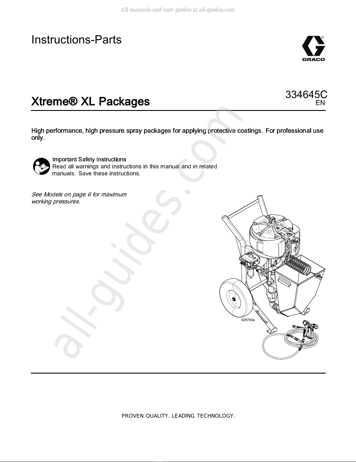
Graco Xtreme XL 45 Parts list manual
Other Graco Paint Sprayer manuals

Graco
Graco TexSpray Compact HP 231-801 Operation manual

Graco
Graco RTX 900 Operating instructions

Graco
Graco 309489 User manual

Graco
Graco Reactor A-25 Use and care manual

Graco
Graco RTX2000 User manual

Graco
Graco PJR REACTOR E-8p Installation guide

Graco
Graco Fire-Ball A Series Operation manual

Graco
Graco HVLP TurboForce II 7.0 Manual

Graco
Graco RTX1400 Guide

Graco
Graco 240054 Operation manual

Graco
Graco LineLazer II 3900 User manual

Graco
Graco 24T946 Operation manual

Graco
Graco M73380 Operation manual

Graco
Graco 311322L Quick start guide

Graco
Graco Merkur G15W Series Parts list manual

Graco
Graco HYDRA-CLEAN C Series Operation manual

Graco
Graco SUPER NOVA SP User manual

Graco
Graco 310813D Operating instructions

Graco
Graco Xtreme NXT User manual

Graco
Graco ti2652b User manual


Popular Paint Sprayer manuals by other brands


zogics
zogics Z-DAS instruction manual

KISANKRAFT
KISANKRAFT KK-KBS-165 Operation manual

Matrix
Matrix SG 650 Translation of the original instructions

Anest Iwata
Anest Iwata SGA-3 Installation, use & maintenance instruction manual

paasche
paasche VV Instructions and parts list

Carlisle
Carlisle DeVilbiss JGA-510 Service manual