WARNINGS
High
Pressure Spray Can Cause Serious Injury. Observe All W
arnings.
Read and understand all instruction manuals before operating equipment.
FLUID
INJECTION HAZARD
General
Safety
This
equipment is used in a system which generates very high
fluid
pressure. Spray from leaks or ruptured components can in
-
ject fluid through your skin and into your body and cause ex-
tremely
serious bodily injury
, including the need for amputation.
Also,
fluid injected or splashed into
the eyes or on the skin can
cause
serious damage.
Never try to stop or deflect leaks with your hand or body
.
Keep
hands away
from the end of the drain valve when opening
the
drain valve.
Medical
Alert – Airless Spray W
ounds
If
any fluid appears to penetrate your skin, get
emergency
medical care at once. Do not treat as a simple cut.
T
ell the
doctor exactly what fluid was injected.
NOTE TO PHYSICIAN:
Injection into the skin is a traumatic
injury.
It is important to treat the injury surgically as soon
as possible.
Do not delay treatment to research toxicity
. T
ox-
icity is a concern with some exotic coatings injected directly
into the blood stream. Consultation with a plastic surgeon or
reconstructive hand surgeon may be advisable.
Pressure
Relief Procedure
To
reduce the risk of serious bodily injury
, including fluid injec
-
tion,
splashing in the eyes or on the skin, or injury from moving
parts, always follow this procedure whenever you install,
remove,
clean or repair any part of the system.
1. Engage the spray gun safety latch and any other equip-
ment safety locks.
2.
Shut of
f the air or hydraulic supply to the pump.
3.
Disengage the gun safety latch.
4. Hold
a metal
part of the gun firmly to the side of a grounded
metal
pail, and trigger the gun to relieve pressure.
5.
Engage the gun safety latch.
6. Keeping
your
hands away from the end of the drain valve,
slowly
open the drain valves (required in your
system) hav
-
ing
a container ready to catch the drainage.
7. Leave
the drain valves open until you are ready to use the
system
again.
EQUIPMENT MISUSE HAZARD
General
Safety
Any misuse of the equipment or accessories, such as
overpressurizing, modifying parts, using incompatible chemi-
cals and fluids, or using worn or damaged parts, can cause
them
to rupture and result in fluid injection, splashing in the eyes
or
on the skin, or other serious bodily injury
, or fire, explosion or
property
damage.
Never
alter or modify any part of this equipment; doing so
could
cause
it to malfunction.
System
Pressure
Do
not exceed
3000 psi (210 bar) Maximum Working
Pressure
,
or the maximum working pressure of the lowest rated compo-
nent or accessory in your system.
Be
sure all components and accessories are
rated to withstand
the
maximum working pressure of your pump.
Fluid
Compatibility
Be
sure that all fluids and
solvents used are chemically compat
-
ible
with the wetted parts shown in the
T
echnical Data
on
page 1 and in all other components used in the system.
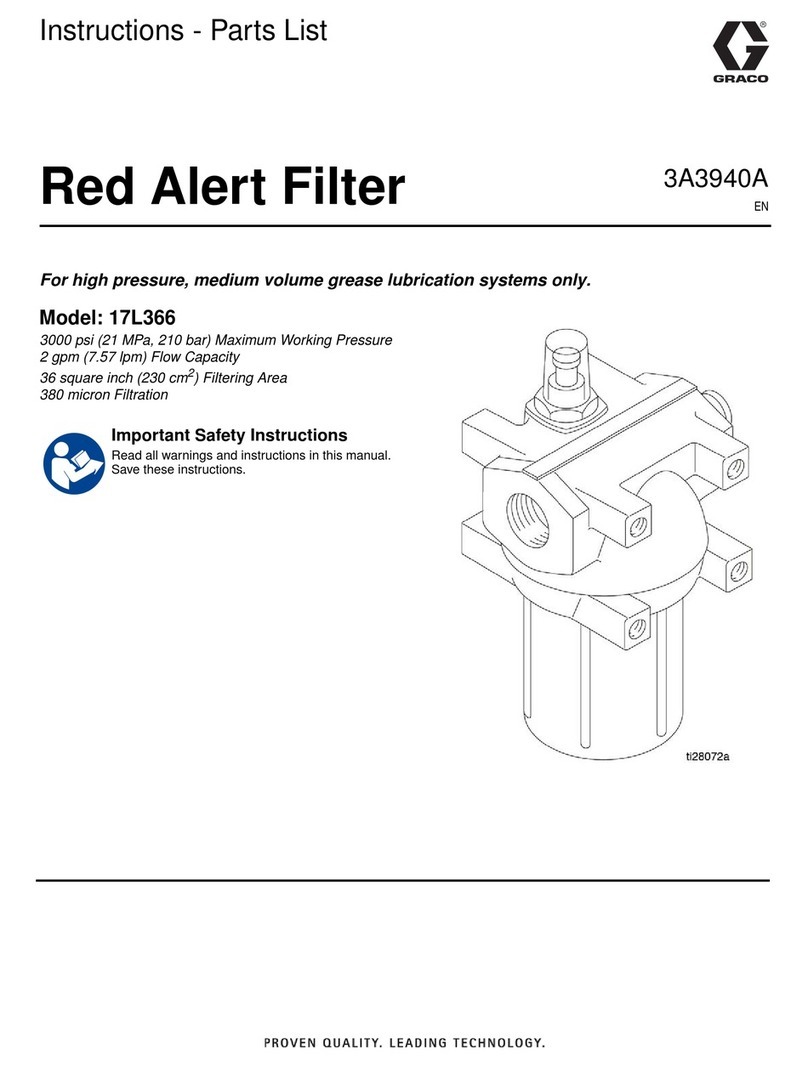
Installation
To
clean or service the filter without shutting down the system,
install
a dual filter or a filter bypass system
as explained below
.
The
numbers and letters in parentheses refer
to Figs. 1, 2, and
3
and the
Parts Drawing.
Accessories
and
T
echnical Data
are
on
the front page.
NOTE:
Allow 3 in. (76 mm) minimum clearance
below the filter
for
easy removal of the bowl (10).
Fluid
Drain V
alve (required in all systems)
WARNING
A
fluid drain valve is required in the base of
each fluid filter
.
Use
this drain valve to relieve fluid pressure in the filter
, to
reduce
the risk of serious injury
, including fluid injection and
splashing
in the eyes or on the skin.
Remove the 3/4 unf plug (12) from the bottom of the filter and
install
a high pressure adapter and drain valve (A,B). See Fig.
1.
Dual Filter System
This
setup enables you to redirect the fluid to
another filter while
one
filter is cleaned or serviced.
Install
two filters
as shown in Fig. 1. Install four suitable shutof
f
valves
(D), one at each filter and outlet, to redirect the fluid
and
isolate
the filter not in use.
Filter Bypass System
This
setup enables you to redirect the fluid through pipes which
bypass
the filter while cleaning or servicing the filter
.
Install
the filter and bypass pipes as shown in Fig. 2. Install four
suitable
shutof
f valves (D), one
each at the filter inlet, the filter
outlet,
the bypass pipe inlet, and the bypass pipe outlet.
These
valves redirect the fluid and isolate the filter while cleaning and
servicing.

