manuals.online logo
Brands
  1. Home
  2. •
  3. Brands
  4. •
  5. Graco
  6. •
  7. Water Pump
  8. •
  9. Graco 24R253 User manual

Graco 24R253 User manual

Other Graco Water Pump manuals
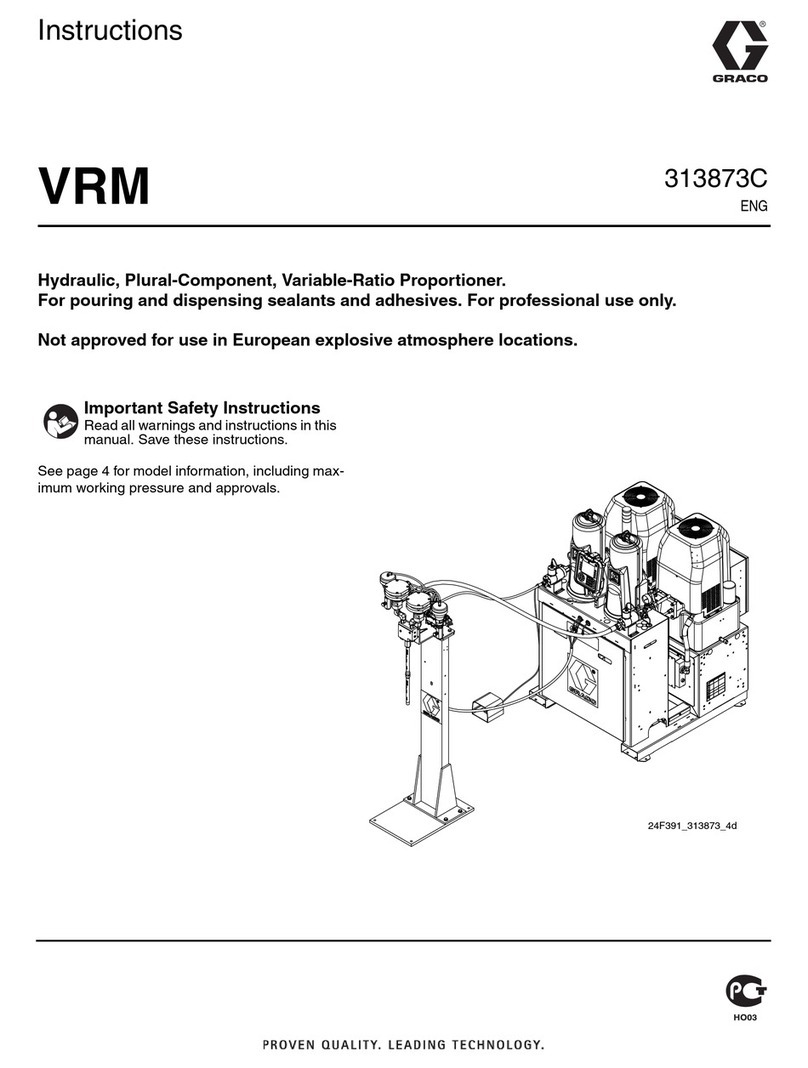
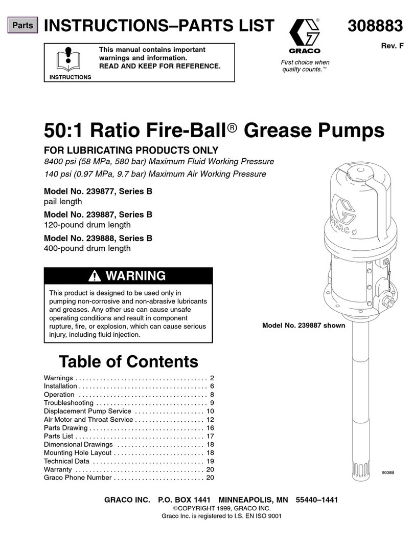
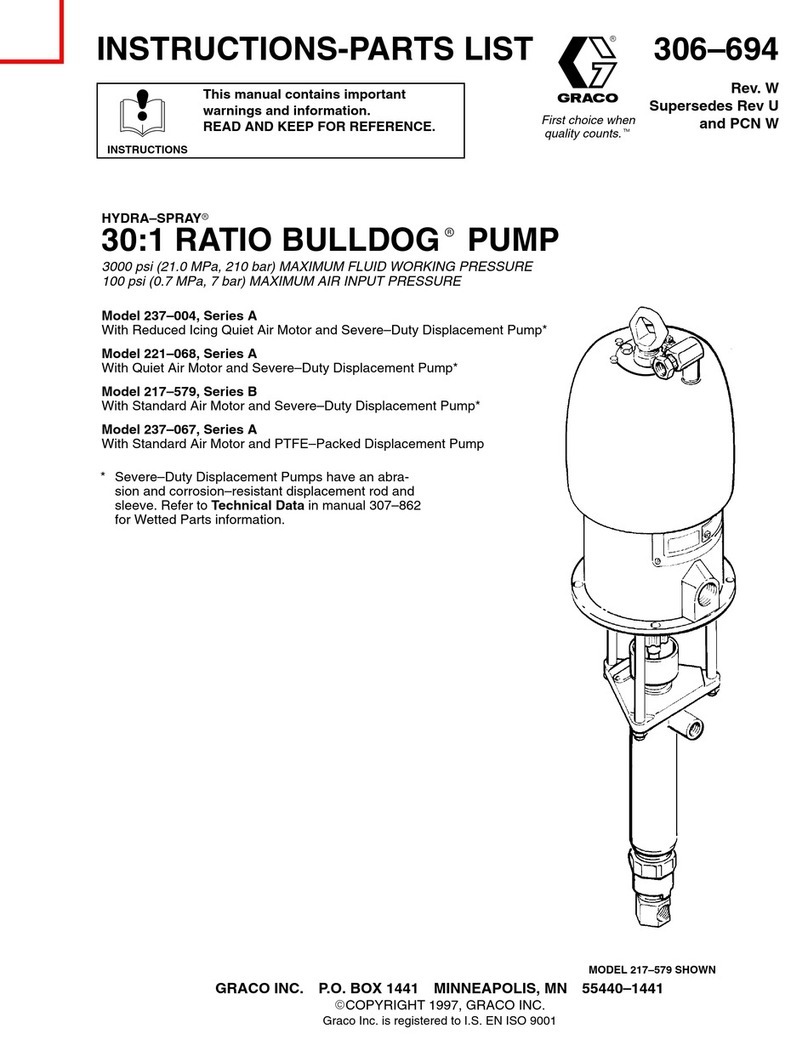
Graco 237-004 Operation manual

Graco

Graco 237-004 Operation manual
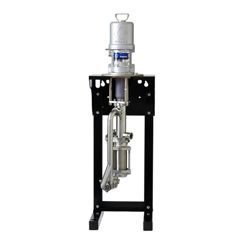
Graco RoadLazer Husky 515 Operation manual

Graco

Graco RoadLazer Husky 515 Operation manual

Graco 258771 Use and care manual

Graco

Graco 258771 Use and care manual

Graco G-Mini Series User manual

Graco

Graco G-Mini Series User manual

Graco Pack'n Play User manual

Graco

Graco Pack'n Play User manual

Graco 205394 Operation manual

Graco

Graco 205394 Operation manual

Graco 190ES 261825 Operating instructions

Graco

Graco 190ES 261825 Operating instructions

Graco G1 User manual

Graco

Graco G1 User manual

Graco 232-504 Operation manual

Graco

Graco 232-504 Operation manual

Graco President E Series Operation manual

Graco

Graco President E Series Operation manual

Graco 3A1335A User manual

Graco

Graco 3A1335A User manual

Graco 24F448 Operation manual

Graco

Graco 24F448 Operation manual

Graco SaniForce STU.A09GAB2AB1C21 Use and care manual

Graco

Graco SaniForce STU.A09GAB2AB1C21 Use and care manual

Graco 248785 Operation manual

Graco

Graco 248785 Operation manual

Graco 256273 User manual

Graco

Graco 256273 User manual

Graco Series E User manual

Graco

Graco Series E User manual

Graco SaniForce 1040 Manual

Graco

Graco SaniForce 1040 Manual

Graco E-Flo SP User manual

Graco

Graco E-Flo SP User manual

Graco Dura-Flo 1100 User manual

Graco

Graco Dura-Flo 1100 User manual

Graco G-Mini 25R800 User manual

Graco

Graco G-Mini 25R800 User manual

Graco Dura-Flo 600 Parts list manual

Graco

Graco Dura-Flo 600 Parts list manual

Graco Dura-Flo 2400 Operation manual

Graco

Graco Dura-Flo 2400 Operation manual

Graco G3 Pro User manual

Graco

Graco G3 Pro User manual

Graco Series A Datasheet

Graco

Graco Series A Datasheet

Popular Water Pump manuals by other brands

Watershed Innovations HYDRAPUMP SMART FLEX Instructional manual

Watershed Innovations

Watershed Innovations HYDRAPUMP SMART FLEX Instructional manual

Messner MultiSystem MPF 3000 operating instructions

Messner

Messner MultiSystem MPF 3000 operating instructions

Xylem Bell & Gossett WEHT0311M Installation, operation and maintenance instructions

Xylem

Xylem Bell & Gossett WEHT0311M Installation, operation and maintenance instructions

WilTec 50739 Operation manual

WilTec

WilTec 50739 Operation manual

Franklin Electric Little Giant 555702 HRK-360S instruction sheet

Franklin Electric

Franklin Electric Little Giant 555702 HRK-360S instruction sheet

Ingersoll-Rand PD02P Series Operator's manual

Ingersoll-Rand

Ingersoll-Rand PD02P Series Operator's manual

VS ZJ Series Operating	 instruction

VS

VS ZJ Series Operating instruction

Flotec FPZS50RP owner's manual

Flotec

Flotec FPZS50RP owner's manual

SKF Lincoln FlowMaster II User and maintenance instructions

SKF

SKF Lincoln FlowMaster II User and maintenance instructions

Xylem Lowara LSB Series Installation, operation and maintenance instructions

Xylem

Xylem Lowara LSB Series Installation, operation and maintenance instructions

Water Duro Pumps DCJ500 Operating & installation instructions

Water

Water Duro Pumps DCJ500 Operating & installation instructions

Action P490 Operating instructions & parts manual

Action

Action P490 Operating instructions & parts manual

Flo King Permacore Reusable Carbon Bag Disassembly. & Cleaning Instructions

Flo King

Flo King Permacore Reusable Carbon Bag Disassembly. & Cleaning Instructions

ARO ARO PD15P-X Operator's manual

ARO

ARO ARO PD15P-X Operator's manual

Pumptec 112V Series Operating instructions and parts manual

Pumptec

Pumptec 112V Series Operating instructions and parts manual

Virax 262070 user manual

Virax

Virax 262070 user manual

Neptun NPHW 5500 operating instructions

Neptun

Neptun NPHW 5500 operating instructions

Sensidyne Gilian BDX-II Operation & service manual

Sensidyne

Sensidyne Gilian BDX-II Operation & service manual

manuals.online logo
manuals.online logoBrands
  • About & Mission
  • Contact us
  • Privacy Policy
  • Terms and Conditions

Copyright 2025 Manuals.Online. All Rights Reserved.

Instructions - Parts
680cc Pump Lower 332649A
EN
High performance, high output, low pressure pump lower. For professional use only.
Important Safety Instructions
Read all warnings and instructions in all manuals.
Save all instructions.
1000 psi (7 MPa, 69 bar) Maximum
Fluid Working Pressure
Model 24R2 3
Contents
Warnings ........................................................... 2
Component Identification..................................... 4
Maintenance ...................................................... 5
Troubleshooting.................................................. 5
Repair................................................................ 6
Parts..................................................................
Technical Specifications...................................... 10
Graco Standard Warranty.................................... 12
Warnings
The following warnings are for the setup, use, grounding, maintenance, and repair of this equipment. The
exclamation point symbol alerts you to a general warning and the hazard symbols refer to procedure-specific
risks. When these symbols appear in the body of this manual or on warning labels, refer back to these
Warnings. Product-specific hazard symbols and warnings not covered in this section may appear throughout
the body of this manual where applicable.
WARNING
FIRE AND EXPLOSION HAZARD
Flammable fumes, such as solvent and paint fumes, in
ork area
canigniteorexplode.Tohelp
prevent fire and explosion:
• Use equipment only in well ventilated area.
• Eliminate all ignition sources; such as pilot lights, cigarettes, portable electric lamps, and
plastic drop cloths (potential static arc).
• Keep work area free of debris, including solvent, rags and gasoline.
• Do not plug or unplug power cords, or turn power or light switches on or off when flammable
fumes are present.
• Ground all equipment in the work area. See
Grounding
instructions.
• Use only grounded hoses.
• Hold applicator firmly to side of grounded pail when triggering into pail. Do not use pail
liners unless they are antistatic or conductive.
•
Stop operation immediately
if static sparking occurs or you feel a shock
.
Do not use
equipment until you identify and correct the problem.
• Keep a working fire extinguisher in the work area.
SKIN INJECTION HAZARD
High-pressure fluid from dispensing device, hose leaks, or ruptured components will pierce
skin. This may look like just a cut, but it is a serious injury that can result in amputation.
Get
immediate surgical treatment.
• Do not point dispensing device at anyone or at any part of the body.
• Do not put your hand over the fluid outlet.
• Do not stop or deflect leaks with your hand, body, glove, or rag.
•Followthe
Pressure Relief Procedure
when you stop dispensing and before cleaning,
checking, or servicing equipment.
• Tighten all fluid connections before operating the equipment.
• Check hoses and couplings daily. Replace worn or damaged parts immediately.
2332649A
Warnings
WARNING
EQUIPMENT MISUSE HAZARD
Misuse can cause death or serious injury.
• Do not operate the unit when fatigued or under the influence of drugs or alcohol.
• Do not exceed the maximum working pressure or temperature rating of the lowest rated
system component. See
Technical Data
in all equipment manuals.
• Use fluids and solvents that are compatible with equipment wetted parts. See Technical Data
in all equipment manuals. Read fluid and solvent manufacturer’s warnings. For complete
information about your material, request MSDS from distributor or retailer.
• Do not leave the work area while equipment is energized or under pressure.
• Turn off all equipment and follow the
Pressure Relief Procedure
when equipment is not in use.
• Check equipment daily. Repair or replace worn or damaged parts immediately with genuine
manufacturer’s replacement parts only.
• Do not alter or modify equipment. Alterations or modifications may void agency approvals
and create safety hazards.
• Make sure all equipment is rated and approved for the environment in which you are using it.
• Use equipment only for its intended purpose. Call your distributor for information.
• Route hoses and cables away from traffic areas, sharp edges, moving parts, and hot surfaces.
• Do not kink or over bend hoses or use hoses to pull equipment.
• Keep children and animals away from work area.
• Comply with all applicable safety regulations.
MOVING PARTS HAZARD
Moving parts can pinch, cut or amputate fingers and other body parts.
• Keep clear of moving parts.
• Do not operate equipment with protective guards or covers removed.
• Pressurized equipment can start without warning. Before checking, moving, or servicing
equipment, follow the
Pressure Relief Procedure
and disconnect all power sources.
TOXIC FLUID OR FUMES HAZARD
Toxic fluids or fumes can cause serious injury or death if splashed in the eyes or on skin,
inhaled, or swallowed.
• Read MSDSs to know the specific hazards of the fluids you are using.
• Store hazardous fluid in approved containers, and dispose of it according to applicable
guidelines.
332649A 3
Component Identification
WARNING
PERSONAL PROTECTIVE EQUIPMENT
Wear appropriate protective equipment when in the work area to help prevent serious injury,
including eye injury, hearing loss, inhalation of toxic fumes, and burns. This protective
equipment includes but is not limited to:
• Protective eyewear, and hearing protection.
• Respirators, protective clothing, and gloves as recommended by the fluid and solvent
manufacturer.
SUCTION HAZARD
Powerful suction could cause serious injury.
• Never place hands near the pump fluid inlet when pump is operating or pressurized.
Component Identification
E
F
D
G
C
B
A
Figure 1
Key:
A Clamps; clamps include flats so only one
wrench is needed to tighten/loosen
B Mounting Plate
CDisplacement Rod
DPacking Nut/Wet Cup
EFluid Outlet
FCylinder
GInlet Housing
4332649A
Maintenance
Maintenance
Regularly check and maintain fluid level in packing
nut/wet cup (D) to 1/2 full with Throat Seal Liquid
(TSL).
Regularly inspect soft parts and replace when worn
or damaged.
Troubleshooting
1. Relieve fluid pressure. See system manual for
pressure relief procedure.
2. Check all possible causes and problems before
disassembling pump.
PROBLEM — CAUSE — SOLUTION
Example:
•
Problem.
–
Cause.
♦ Solution.
•
Output lo on do n-stroke.
–
Open or worn intake valve.
♦ Clear or service intake valve.
•
Output lo on up-stroke.
–
Open or worn piston valve or packings.
♦ Clear piston valve; replace packings.
•
Erratic accelerated speed.
–
Fluid supply exhausted, clogged suction.
♦ Refill fluid supply container and prime pump.
–
Open or worn piston valve or packings.
♦ Clear piston valve; replace packings.
–
Open or worn intake valve.
♦ Clear or service intake valve.
•
Cycles or fails to hold pressure at stall.
–
orn check balls, seats, or piston packing.
♦ Service lower. See Repair, page 6 .
332649A 5
Repair
Repair
Suggested Tools
• 5/ in. box end wrench or 5/ in. socket and ratchet
• Rubber mallet (to break items loose, if necessary)
102
135
105
135
102
104
137
125
122
126
103
109
112
120
140
133
134
119
114
110
111
108
107
121
123
115
106
124
113
4
11
5
5
8
12
ti22049a
Figure 2
See the figure at the beginning of this section.
NOTE:
As items are disassembled, use a
soft brush and water or a compatible solvent
to clean components.
1. Perform Pressure Relief Procedure.
NOTICE
Ensure material pressure is relieved prior to
removing the fluid hose from the system.
2. Remove inlet and outlet hoses from pump lower.
3. Disconnect pump lower from motor and remove
pump lower from system.
4. While holding onto the inlet housing (109), use
a5/ in. wrenchtoloosenthetwonutsonthe
inlet housing clamp (102) then remove inlet
housing assembly (109 and 103).
6332649A
Repair
NOTE:
Hold onto assembly firmly when removing
clamp. Part will disengage and fall.
5. Remove inlet ball stop (104).
6. Clean the inlet housing assembly (109 and 103),
inlet ball (125), and inlet ball stop (104).
NOTE:
The inlet housing assembly (109 and
103) is not disassembled unless the inlet seat
needs to be replaced.
7. Use5/ in.wrenchtoloosenthetwonutsonthe
cylinder clamp (102) then remove cylinder (105).
. Pull rod (111) down and out of outlet
housing (110).
9. Remove outlet ball stop (10 ) from rod (111) by
pushing o-rings off of ball stop (10 ).
10. Clean outlet ball stop (10 ), outlet ball stop
o-rings, and rod (111).
The pump rod (111) is not disassembled unless
the piston packing or seat needs to be replaced.
11. Loosen and remove packing nut (112) then
remove throat packing (114).
12. Clean the cylinder (105), two cylinder
o-rings (135), outlet housing (110), throat
packing (114), and packing nut (112).
Assemble the Pump
1. Loosely install throat packing (114) with the open
end facing into the pump with packing nut (112).
2. Install outlet ball (123), outlet ball stop (10 ) with
o-rings into rod (111). Ensure outlet ball stop
o-rings are in the grooves on the outlet ball stop
rod.
3. Gently slide rod (111) through throat
packing (114).
4. Tighten packing nut (112) until it stops.
NOTE:
This is not an adjustable packing.
5. Slide cylinder (105) over rod (111) with
o-ring (135) installed between outlet
housing (110) and cylinder (105).
6. Use cylinder clamp (102) to secure cylinder (105)
to outlet housing (110).
NOTE:
The clamp has flats so that
onlyonewrenchisrequiredtotighten
clamp. Alignboltheadwithflatthen
use a wrench on the nut to tighten.
Tightenbothsidesoftheclampevenlyto
approximately 20–30 ft-lb (27–41 N•m).
7. Install inlet ball (125) and inlet ball stop (104) in
inlet housing (109).
. With inlet ball (125) and inlet ball stop (104) in
place, place o-ring (135) between cylinder (105)
and inlet housing (109) then use inlet housing
clamp (102) to install inlet housing (109) onto
cylinder (105).
NOTE:
The clamp has flats so that
onlyonewrenchisrequiredtotighten
clamp. Alignboltheadwithflatthen
use a wrench on the nut to tighten.
Tightenbothsidesoftheclampevenlyto
approximately 20–30 ft-lb (27–41 N•m).
9. Connect pump lower to motor.
10. Connect inlet and outlet hoses to pump lower.
11. Add TSL to the packing nut (112) around the rod.
332649A 7
Parts
Parts
102
135
105
135
102
104
137
125
122
126
103
109
112
120
140
133
134
119
114
110
111
108
107
121
123
115
106
124
113
4
11
5
5
8
12
ti22049a
NOTE: Apply clear, liquid petrolatum to
threads, o-rings, and seals.
NOTE: Tighten lock nut (119), keeping
mounting plate (120) within +/- 0.060 inch
(1.5 mm) of being flush with housing (110).
4
Torque to 25–35 ft-lb (34–47 N∙m).
5
Torque to 90–110 ft-lb (122–149 N∙m).
8
Apply medium strength thread-locking fluid
to threads.
11
Assemble plate (120) within +/- 0.060 inch
(1.5 mm) of being flush with housing (110),
with 1 inch npt hole in line with flats on
plate (120).
12
Torque to 190–210 ft-lb (25 –2 5 N∙m).
Ref Part Description Qty
10216E963 CLAMP, double-
bolted, 4 inch 2
103 16U796 HOUSING, inlet 1
104 16U797 STOP, ball 1
Ref Part Description Qty
10516U79 CYLINDER, pump 1
106 16U799 VALVE, piston 1
107 16U 00 HOLDER, valve piston 1
8332649A
Parts
Ref Part Description Qty
10 16U 01 STOP, upper ball 1
109 16V143 HOUSING, inlet, 2
inch cam and groove 1
110 16U 03 HOUSING, outlet 1
111 16U 04 ROD, displacement 1
112 16U 05 NUT, packing 1
113*◆● --- O-RING, PTFE, 35mm
x2.5mm 1
114◆● 16W492 BEARING, seal, throat
(3–pack) 1
115◆● 16W491 PACKING, cup, piston
(3–pack) 1
119 16U977 NUT, jam 1
120 16U976 PLATE, mounting,
cylinder 1
121◆● 16W519 PACKING, o-ring,
solvent-resistant
(6–pack)
2
Ref Part Description Qty
122■◆● --- O-RING, 50mm x
2.5mm 1
123◆ 102973 BALL, hardened
stainless steel
(3–pack: 16W493)
1
124* --- SEAT 1
125◆ 112420 BALL, hardened
stainless (3–pack:
16W494)
1
126■ --- SEAT 1
133 --- SCREW, drive 2
134 --- PLATE, identification 1
135◆● 16W490 PACKING, o-ring,
cylinder (10–pack) 2
137 16W472 SPRING, guide, ball 1
140
▲
15H10 LABEL, pinch point 1
▲
Replacement Danger and arning labels, tags,
and cards are available at no cost.
*
Parts included in Piston Seat Repair Kit 16 509
(purchase separately).
■
Parts included in Inlet Seat Repair Kit 16 510
(purchase separately).
◆
Parts included in Pump Rebuild Kit 16 508
(purchase separately).
●
Parts included in Soft Seal Rebuild Kit 24U173
(purchase separately).
---
Not for sale.
332649A 9
Technical Specifications
680cc Pump Lo er
U.S. Metric
Maximum Working Pressure 1000 psi 7 MPa, 70 bar
Fluid Supply Type Gravity Feed
Stroke Length 4.75 in. 120 mm
Height (rod extended) 23.75 in. 0.603 m
Height (rod retracted) 19.0 in. 0.4 3 m
Lower Output 41.9 cu. in. per cycle 6 6 cc per cycle
Flow Rate at 30 cycles per minute 5.44 gpm 20.6 lpm
Flow Rate at 60 cycles per minute 10. gpm 41.2 lpm
Fluid Inlet Size 2 in. Cam Groove (Male)
Fluid Outlet Size 1 npt(f)
Weight (without fluid) 47 lb 21 kg
Maximum Pump Speed
(Do not exceed maximum recommended pump speed of fluid pump to prevent premature pump wear)
Spraying 40 cycles per minute (typically less than 10 cycles per minute)
Flushing 60–90 cycles per minute (only when pumping flushing fluid)
Wetted Parts Stainless steel, UHMWPE, PTFE, carbide seats, sol-
vent-resistant elastomer
10 332649A