Contents
2 3A6714H
Contents
DC Models. . . . . . . . . . . . . . . . . . . . . . . . . . . . . . . . . 3
AC Models . . . . . . . . . . . . . . . . . . . . . . . . . . . . . . . . . 4
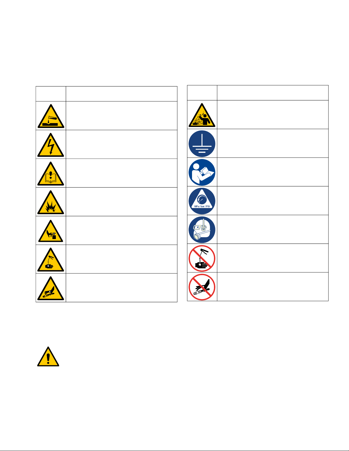
Safety Symbols . . . . . . . . . . . . . . . . . . . . . . . . . . . . . 5
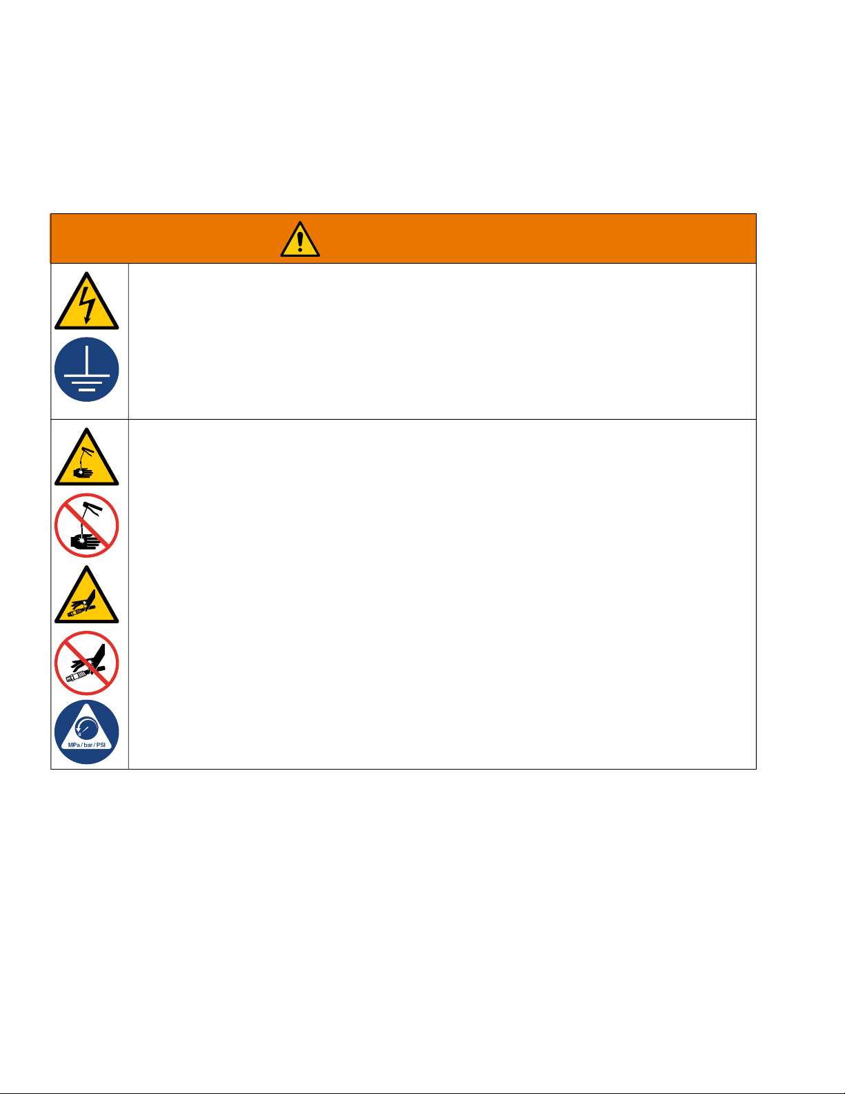
General Warning . . . . . . . . . . . . . . . . . . . . . . . . . . . . 6
Typical Installation . . . . . . . . . . . . . . . . . . . . . . . . . . 8
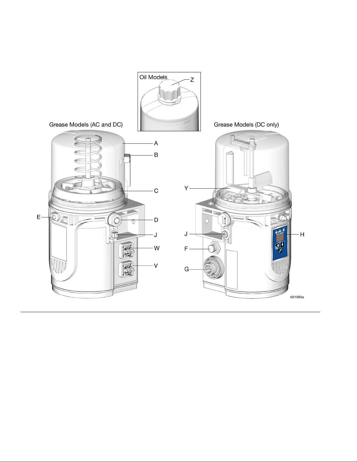
Component Identification . . . . . . . . . . . . . . . . . . 8
Divider Installation Remote . . . . . . . . . . . . . . . . . 9
CSP Direct Mount Installation . . . . . . . . . . . . . . . 9
Installation. . . . . . . . . . . . . . . . . . . . . . . . . . . . . . . . 10
Choose an Installation Location . . . . . . . . . . . . 10
System Configuration and Wiring . . . . . . . . . . . 11
Grounding (AC Models Only) . . . . . . . . . . . . . . . 11
Fuses . . . . . . . . . . . . . . . . . . . . . . . . . . . . . . . . . 11
Recommendations for Pump Usage in
Harsh Environments . . . . . . . . . . . . . . . . . . 12
Wiring and Installation Diagrams . . . . . . . . . . . . 12
Manual Run Button . . . . . . . . . . . . . . . . . . . . . . 16
Proximity Switch . . . . . . . . . . . . . . . . . . . . . . . . 17
Setup . . . . . . . . . . . . . . . . . . . . . . . . . . . . . . . . . . . . 18
Pressure Relief Procedure . . . . . . . . . . . . . . . . . 18
Connect to Auxiliary Fittings . . . . . . . . . . . . . . . 18
Pressure Relief Valves . . . . . . . . . . . . . . . . . 18
Pressure Relief Valves . . . . . . . . . . . . . . . . . . . . 18
Set Pump Outlet Volume . . . . . . . . . . . . . . . . . . 19
Fill Reservoir - Grease Dispense Pumps . . . . . . 19
Models With a Follower Plate . . . . . . . . . . . 20
Models Without a Follower Plate. . . . . . . . . 20
Change Greases . . . . . . . . . . . . . . . . . . . . . 21
Fill Reservoir - Oil Dispense Pumps . . . . . . . . . 21
Prime the Pump . . . . . . . . . . . . . . . . . . . . . . . . . 21
Operation . . . . . . . . . . . . . . . . . . . . . . . . . . . . . . . . . 23
Non Controller Operation . . . . . . . . . . . . . . . . . . 23
Low-Level Output Option. . . . . . . . . . . . . . . 23
Controller Operation . . . . . . . . . . . . . . . . . . . . . . 25
Control Panel Overview (FIG. 29) . . . . . . . . . 25
RUN MODE . . . . . . . . . . . . . . . . . . . . . . . . . . . . 26
SETUP MODE . . . . . . . . . . . . . . . . . . . . . . . . . . 26
ON TIME Configuration (Minutes) . . . . . . . . 26
ON TIME Configuration (Cycles) . . . . . . . . . 27
OFF TIME Configuration (Min./Hrs) . . . . . . . 28
ADVANCED PROGRAMMING . . . . . . . . . . . . . . 28
Advanced Programming
Menu Descriptions . . . . . . . . . . . . . . . . 29
Alerts and Alarms . . . . . . . . . . . . . . . . . . . . . . . . 32
Alerts . . . . . . . . . . . . . . . . . . . . . . . . . . . . . . . . . 32
Alarms . . . . . . . . . . . . . . . . . . . . . . . . . . . . . . . . 32
Alert and Alarm Scenarios . . . . . . . . . . . . . . . . . 33
Maintenance . . . . . . . . . . . . . . . . . . . . . . . . . . . . . . 34
Recycling and Disposal . . . . . . . . . . . . . . . . . . . . . 35
End of Product Life. . . . . . . . . . . . . . . . . . . . . . . 35
Troubleshooting . . . . . . . . . . . . . . . . . . . . . . . . . . . 36
Repair. . . . . . . . . . . . . . . . . . . . . . . . . . . . . . . . . . . . 37
Reservoir Kits . . . . . . . . . . . . . . . . . . . . . . . . . . . 37
Pump Element Kits. . . . . . . . . . . . . . . . . . . . . . . 37
Parts . . . . . . . . . . . . . . . . . . . . . . . . . . . . . . . . . . . . . 38
Dimensions . . . . . . . . . . . . . . . . . . . . . . . . . . . . . . . 40
CSP Valve Bracket Mount . . . . . . . . . . . . . . . . . 41
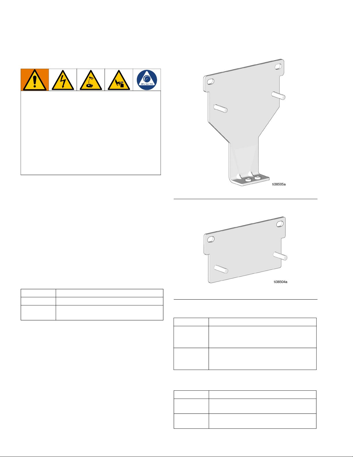
2L Model Pump Mount. . . . . . . . . . . . . . . . . . . . 41
0.5L and 1L Model Pump Mount . . . . . . . . . . . . 41
Universal Bracket Mount . . . . . . . . . . . . . . . . . . 41
Technical Specifications . . . . . . . . . . . . . . . . . . . . 42
California Proposition 65 . . . . . . . . . . . . . . . . . . . . 43
Graco Standard Warranty. . . . . . . . . . . . . . . . . . . . 44