info@graf.info
www.graf.info
15 / 36
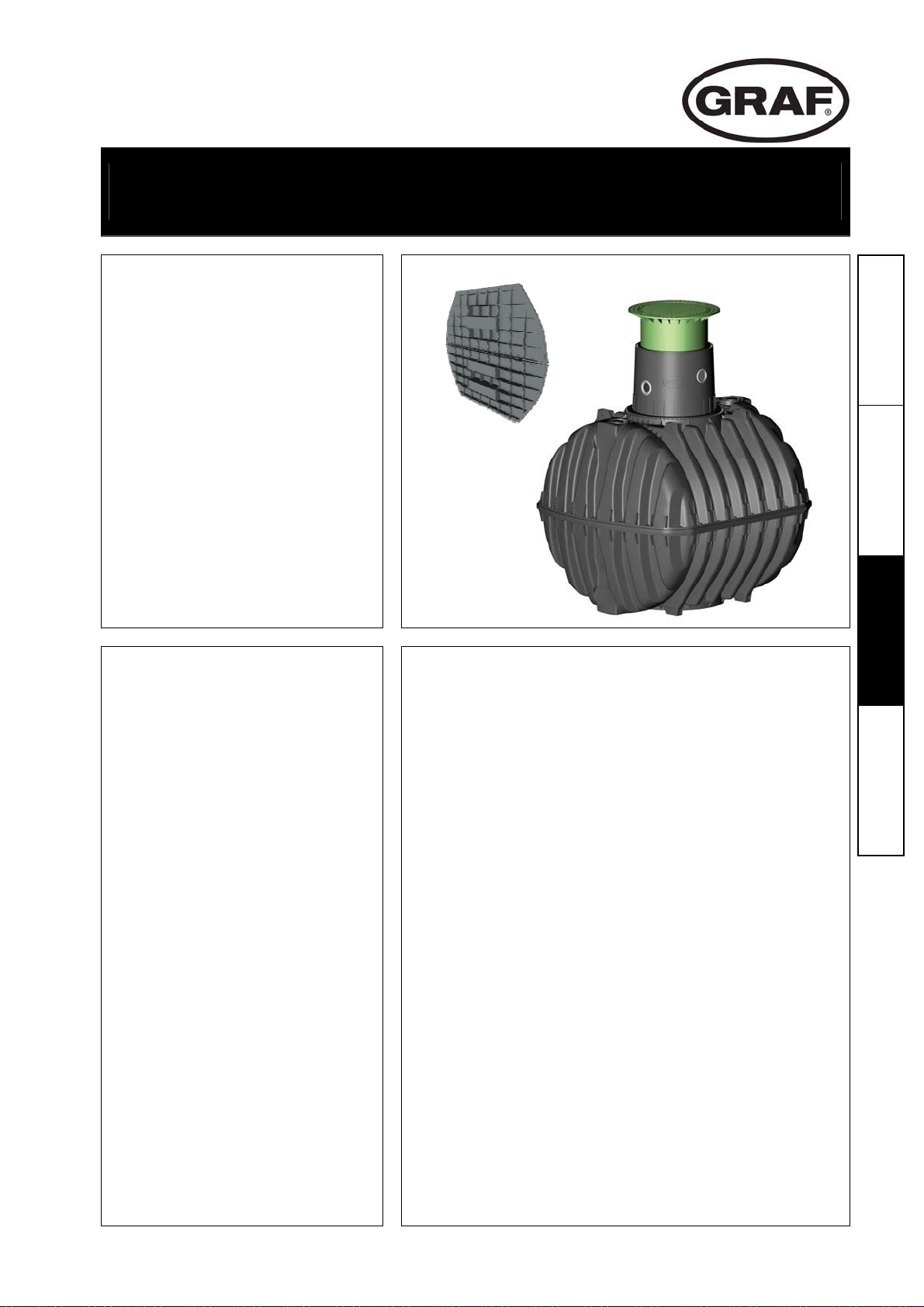
3.750 L
5. Installation and assembly
5.1 Construction site
Under all circumstances, the following points must be clarified prior to installation:
The structural suitability of the ground according to DIN 18196
Maximum groundwater levels which occur and drainage capability of the subsoil
Types of load which occur, e.g. traffic loads
An expert ground report should be requested from the local planning authority to determine the physical
characteristics of the subsoil.
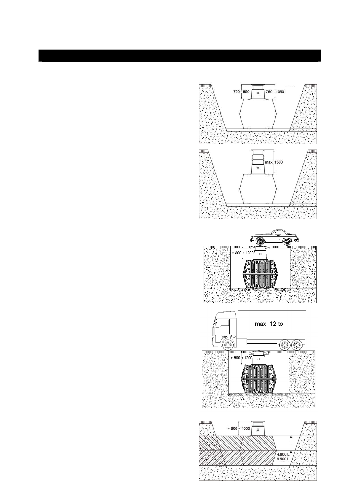
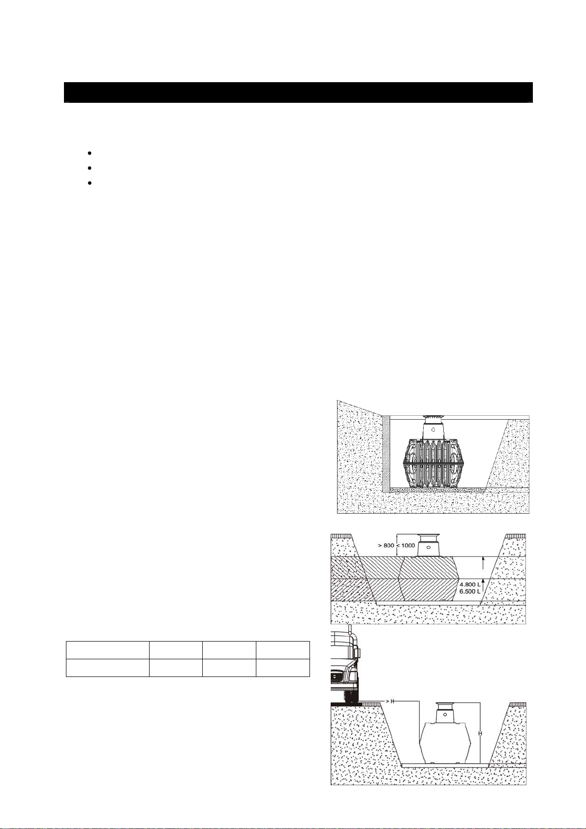
5.2 Trench
To ensure that sufficient space is available for working, the base area of the trench must exceed the
dimensions of the tank by 500 mm on each side; the distance from solid constructions must be at least
1000 mm.
The embankment must be designed according to DIN 4124. The construction site must be horizontal and
plane and must guarantee sufficient load-bearing capacity.
The depth of the trench must be dimensioned so that the max. earth coverage (see point 2 – installation
conditions) above the tank is not exceeded. To use the system throughout the entire year, it is necessary
to install the tank and those parts of the system which conduct water in the frost-free area. The frost-free
depth is usually approx. 600 mm – 800 mm; precise information in this regard can be obtained from the
responsible authority.
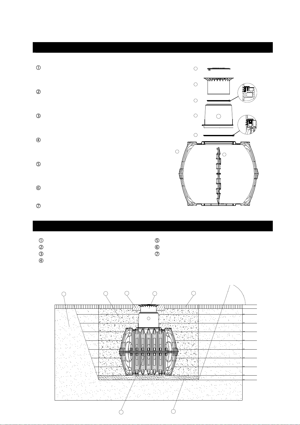
A layer of compacted, round-grain gravel (grain size 8/16, thickness approx. 150 - 200 mm) is applied as
the foundation.
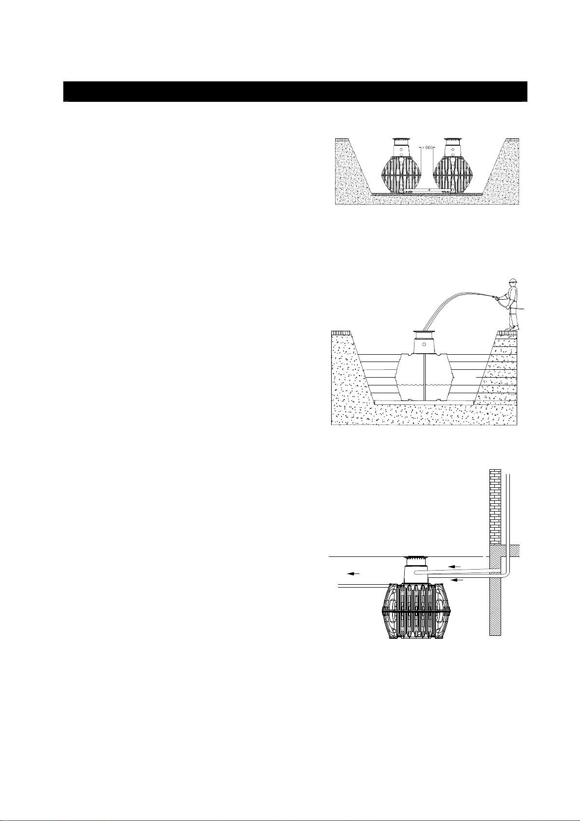
5.2.1 Slope, embankment, etc.
On installation of the tank in the immediate vicinity (< 5 m)
of a slope, earthen mound or slope, a statically calculated
supporting wall must be erected to absorb the soil
pressure. The wall must exceed the dimensions of the
tank by at least 500 mm in all directions, and must be
located at least 1000 mm away from the tank.
5.2.2 Groundwater and cohesive (water-impermeable)
soils (e.g. clay soil)
If it is anticipated that the tanks will be immersed deeper
into the groundwater than is shown in the adjacent figure,
sufficient dissipation must be ensured. (See table for
max. immersion depth).
Dissipation of the drainage water (e.g. via an annular
drainage system) is recommended in the case of
cohesive, water-impermeable soils.
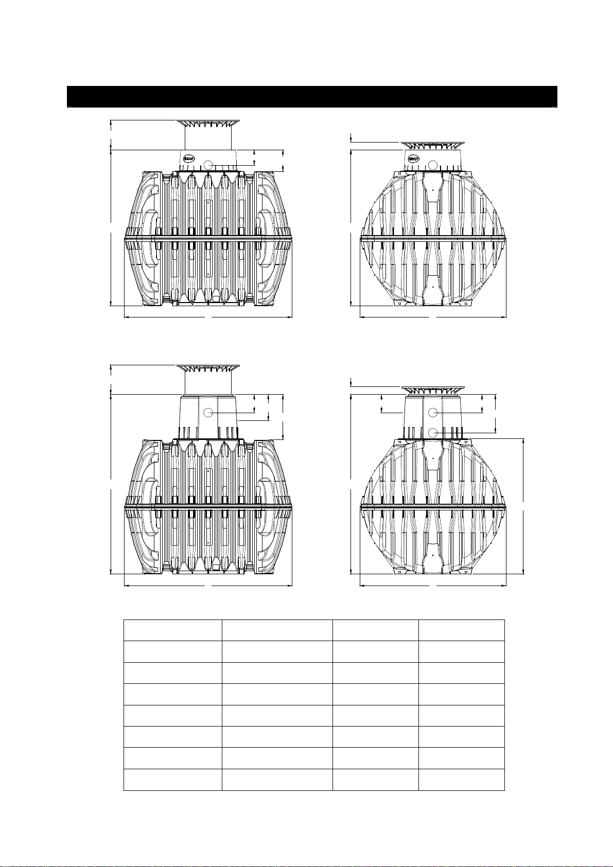
Tank size 3750 L 4800 L 6500 L
Immersion depth 1590 mm 910 mm 1050 mm
5.2.3 Installation adjacent to surfaces used by
vehicles
If the underground tanks are installed adjacent to
surfaces which are used by heavy vehicles weighing over
12 t, the minimum distance away from these surfaces is
at least the depth of the trench.