Granberg Verti 830 User manual

Verti 830/831
Doc. No: M830/831
Edition: 5
Date: 2012-12-07
INSTRUCTION MANUAL
Verti 830 / 831
Granberg Interior AB
Box 6112
SE-600 06 Norrköping
SWEDEN
English

For more information, see:
www.granberg.se

Section: Headline: Page:
1. Introduction.................................................................................................................................................... 4
2. Declaration of Conformity ......................................................................................................................... 4
3. Intended use - Technical data................................................................................................................... 4
Installation instructions:
4.1 Mechanical construction............................................................................................................................ 5
4.2 Delivery modules.......................................................................................................................................... 5
4.3 Joist heights.................................................................................................................................................... 6
4.4 Location wall socket and control devices ............................................................................................ 7
4.5 Preparations.................................................................................................................................................... 8
4.6 Installation on wall ....................................................................................................................................... 9
4.7 Installation of lighting under the safety panel (accessory)..........................................................10
4.8 Installation of light ramp (accessory)...................................................................................................
10
4.9 Functional test...............................................................................................................................................10
Operator’s information:
5.1 Safe use...........................................................................................................................................................11
5.2 Safety arrangements .................................................................................................................................13
5.3 Load distribution and side forces .........................................................................................................13
5.4 Actions after use..........................................................................................................................................13
5.5 Alternative control devices .....................................................................................................................14
5.6 Cleaning .........................................................................................................................................................14
5.7 Maintenance.................................................................................................................................................15
6. Instructions for Recycling ........................................................................................................................15
7. Decals..............................................................................................................................................................16
8. Warranty.........................................................................................................................................................16
9. Service & maintenance records .............................................................................................................17
10. Fault finding..................................................................................................................................................18
11. Spare parts list..............................................................................................................................................18
12. Electric circuit diagram .............................................................................................................................19
13. CE-Declaration of Conformity ................................................................................................................19
Content

4
1. Introduction
We have the pleasure to deliver a Granberg Interior Verti lift unit for installation in wall cabinets.This is an electrically oper-
ated lifting and lowering system for installation in new or existing wall cabinets.It can be used separately, or together with the
Granberg work top units, and it becomes then a total adaptation of the kitchen.The lift is suitable for all wall cabinets of
various makes,which are made according the standards EN 1116 and EN 1153.
Only authorized persons may use the Verti!
Authorization means obligation to read and follow the instructions.
It is very important that you read and understands the instructions before you use Verti.
If you have any questions - contact your supplier.
This Instruction manual shall be available for all concerned persons,be kept in a protected place and shall follow the product, if
it is moved to another installation site or another house or apartment owner.
Correct use, operation, inspections and maintenance are
decisive for efficient and safe work.
2. Declaration of Conformity with EU-directive
This product is CE-marked and is granted to conform to the basic safety and operation requirements, in accordance with de
actual Machinery, EMC- and Low voltage Directives. A separate “CE-Declaration of Conformity” is available in section 13.
3. Intended use - Technical data
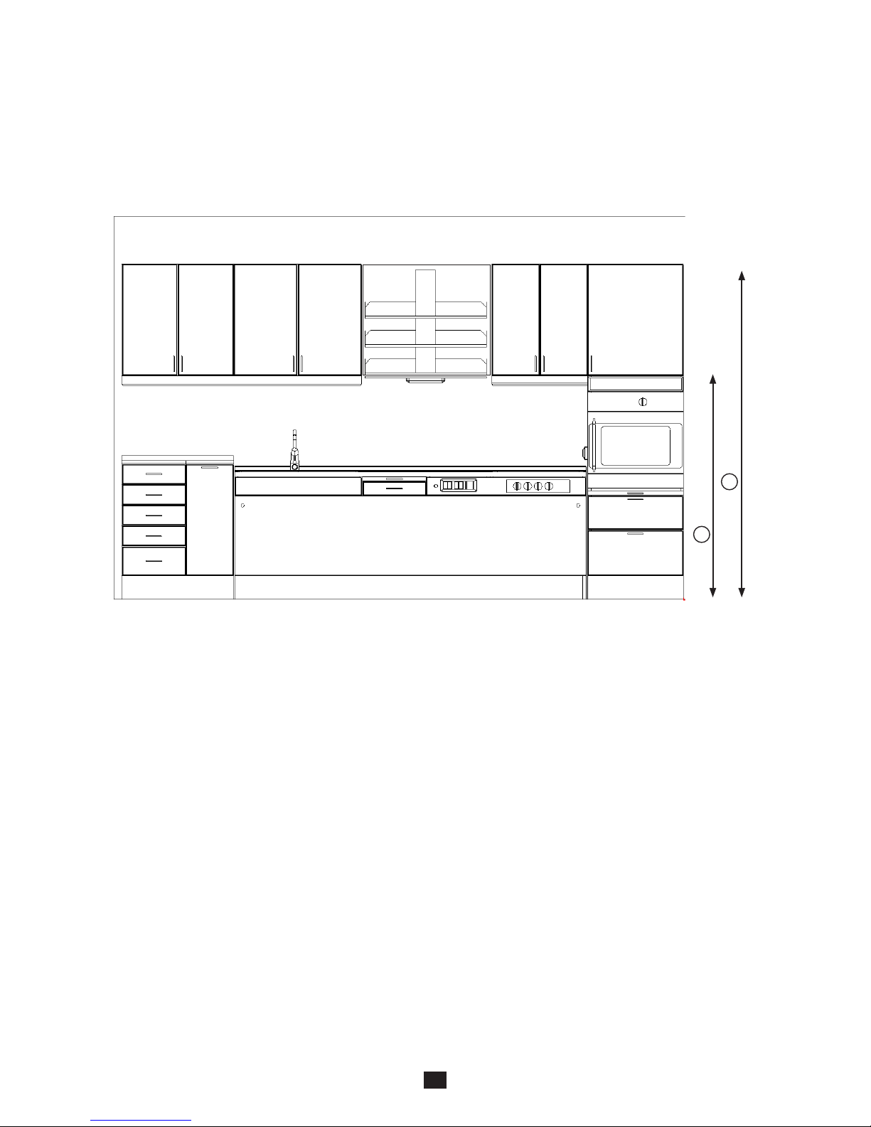
The Verti Cabinet lift unit is intended to achieve a convenient location to put or pick of normal kitchen cabinet items, e.g. dry
groceries and household objects, by means of manoeuvring the shelf system vertically.Verti is mounted in a kitchen cabinet
of massive wood or of lacquered or laminated chipboards.The operation shall be indoors, under normal housing conditions
regarding temperature,humidity and lighting.
Verti is not intended for use in moist environments.
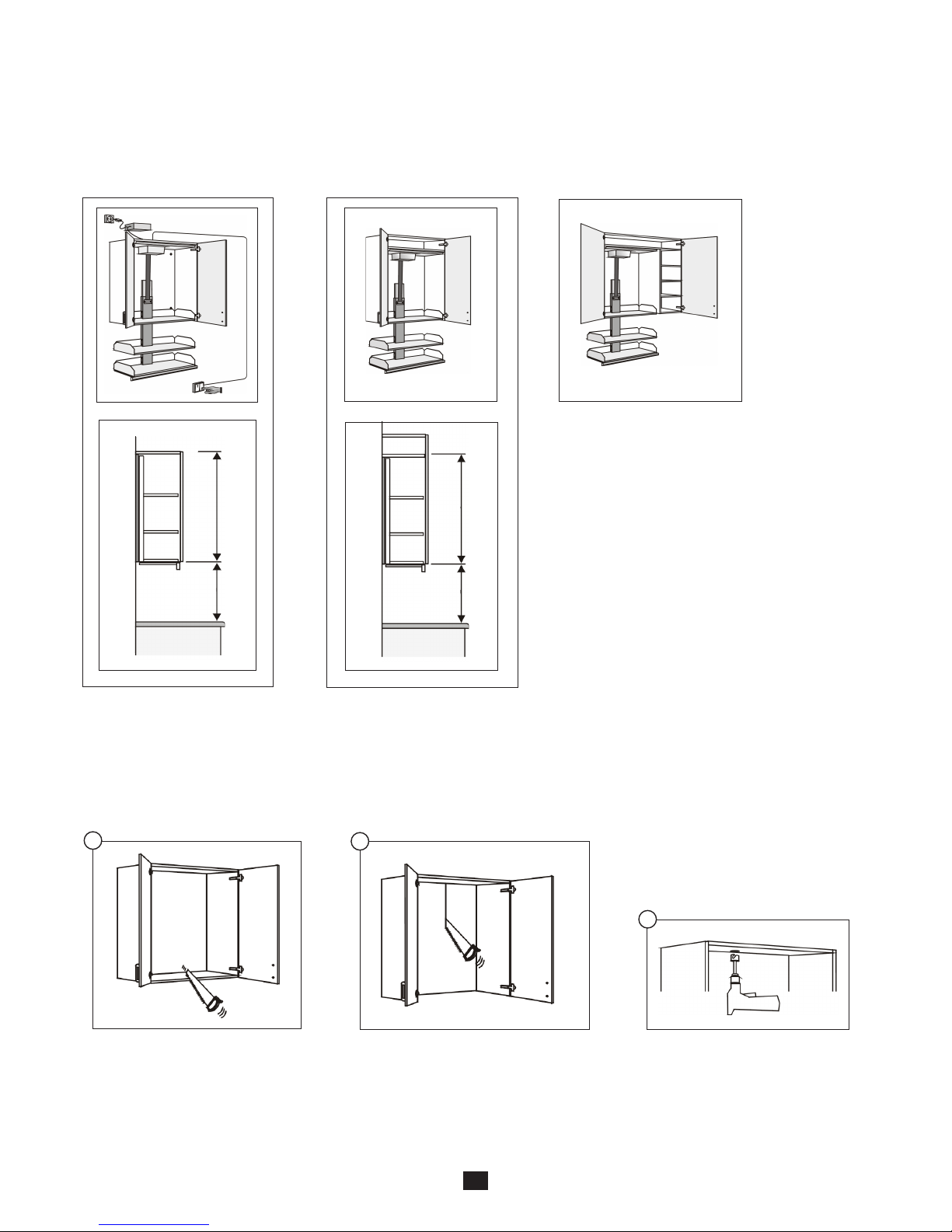
The Verti Cabinet lift unit is delivered for installation in a new cabinet frame,comprising sides and a top board,or for
installation in existing cabinet.The shelves and the bottom board and possible backboard must be demounted before the
Verti is installed.
It is assumed that the wall cabinet is made according the standards EN 1116 and EN 1153.
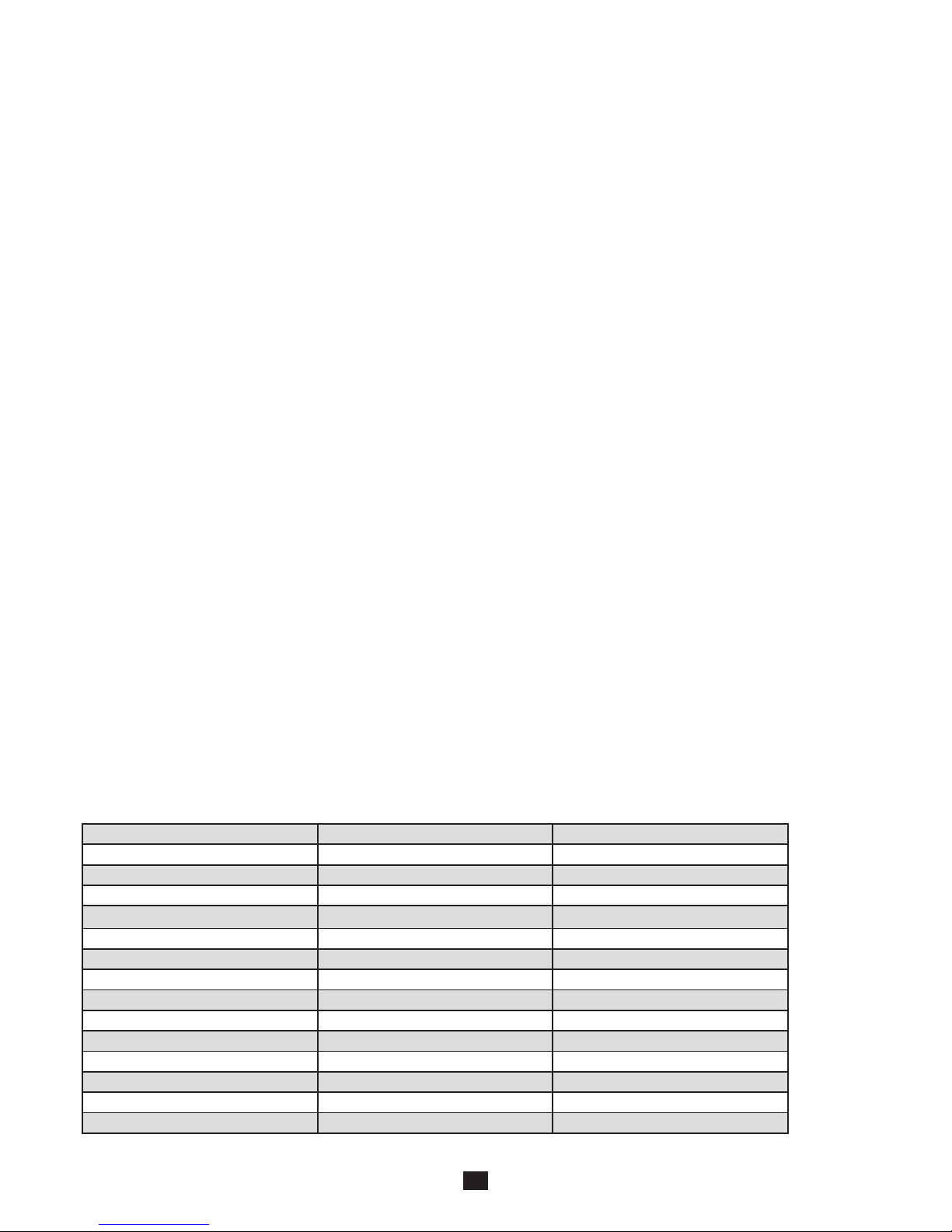
Technical data, Verti 830 / 831
Model 830 831
Cabinet width (inside) 360 - 960 mm 360 - 960 mm
Length of shelves 306 - 906 mm 306 - 906 mm
Cabinet height Min. 700 mm Min. 700 mm
Cabinet depth, min 265 mm 310 mm
Depth of shelves 242 mm 286 mm
Vertical stroke, max 470 mm 470 mm
Time for a lift or lowering stroke, approx. 10 s 10 s
Mains voltage* 120 V 1,5 A / 230 V 0,5 A 120 V 1,5 A / 230 V 0,5 A
Power consumption* 180 W / 105 W 180 W / 105 W
Max no. of full work cycles per hour 6 6
Control and lighting voltage 24 V DC 24 V DC
Weight including shelves, max. size 28 kg 28 kg
Max load in a cabinet 40 kg 40 kg
Noise pressure Less than 70 dB(A) Less than 70 dB(A)
* The voltage depends on which model that is delivered.

5
x 2
x 12
4x16
4x35
4.1 Mechanical construction
The Verti Cabinet lift unit comprises a rear panel, to be mounted on a wall,a
lifting mechanism and a rack with 3 shelves.The vertical lifting and lowering
motions are made by an electrically powered lifting belt, which is fitted
between the rear panel and the shelf rack.
4.2 Delivery modules
The Verti unit is delivered in a box completely assembled with shelves, lifting mechanism, control system, and upper and
lower trip plate. The lift can be completed with various control units, light ramp and lighting.
Verti shelf unit Attachment brackets Motor cover
Screws Transformer Control button Lighting (accessory)

6
-------------------
-----------------------------------------------------------------------------
---------------------------------------------------------------------
1440 mm
2052 mm
B
A
4.3 Joist heights for Verti
The Verti unit is fixed to the wall through the rear panel. Laying joists shall be placed according to the dimensions below:
A = 1440 mm from floor to centre of the joist
B = 2052 mm from floor to centre of the joist

7
A
E
BC
D
4.4 Location of sockets and control devices
The Verti unit shall be connected to a separate main switch, which is placed in the kitchen or its vicinity. The location of a
socket for 230 V, 50 Hz / 120 V, 60 Hz (depends on model) should be coordinated with other equipment in the kitchen. The
Verti wall cabinet system is often in combined with a worktop system. See pictures below for proposed locations.
A - Socket
The socket is placed above the cabinet.
B - Location of VP-tube for control cable
A VP-tube is placed in the wall behind the Verti. In this the cable to the control button placed. The lower part of the tube shall
exit from the wall just above the floor if the kitchen is equipped with a worktop lift. The upper part of the tube shall exit above
the cabinet. The cable length is 5 meters.
C - Alternative location of control cable
Alternative location of the control cable is through a high cabinet. The cable length is 5 meters.
D - Proposed location of recessed buttons
Proposed location of button if the kitchen is equipped with a worktop lift. (Recessed buttons).
E - Proposed location of outside buttons
When the kitchen is not equipped with a worktop lift the button can be placed e.g. on the side of a high cabinet (approx. 110
cm above the floor if it is placed above a worktop lift), inside a floor cabinet etc.
No socket to the lighting is required. It is connected to the circuit board of the Verti units. See section 12.

8
70 cm50 cm
> 70 cm
50 cm
12
3
4.5 Preparations
The Verti unit shall be mounted inside a wall cabinet. Avoid placing Verti above the water tap, as this can prevent the Verti to
be lowered to the bottom position. If necessary choose a low water tap.
4.5.1 Location in cabinet
Remove the shelves.
Remove the cabinet bottom.
Make holes for cables in the
cabinet top. Hole diameter min.
20 mm.To be placed approx.150
mm to the left of the cabinet
centre, and approx. 30 mm from
the wall.
Remove the rear panel (backside),un-
less it is firmly fixed to the wall.
Check that the wall has sufficient
strength for the Verti unit, including
the maximum load.
4.5.2 Preparations at installation of Verti in existing wall cabinet
Mount the Verti unit to the
cabinet top plate.
At cabinet height 70 cm:
At cabinet height more than
72 cm add an additional, fixed
mounted shelf in the cabinet.
At cabinet height more than 70 cm: Example on alternative installation:

9
13
456
79
A
2
8
Adjust the top position
by means of moving
the consoles (A) up or
down.
Fix the motor cover with the screws.
The rear part shall hang in consoles
on the rear panel. The front part shall
be screwed into the cabinet top.
Remove the protection film from the
cover.
Install the transformer on the cabinet top
plate alternatively on a fixed shelf in an adja-
cent cabinet.The socket shall be possible to
reach after the installation is finished.
* Connect the cable to the UP/DOWN control
unit acc.picture. Make sure that the cable can-
not be jammed.
The connection to the socket shall
be easily accessible,so that it can be
disconnected when needed.
The cable shall be placed so that it is
not exposed to heat.
Connection on the printed circuit
board
C= Current in 18 V from transformer
D = Possible mains feed to the
next Verti unit
E = Control devices UP/DOWN
4.6 Installation on wall
Fix the consoles in the corners, so
that the Verti unit supports the
cabinet sides.
Place the Verti unit in the cabinet. Fix the Verti unit rear panel fast in
the wall with at least 6 screws.
The Verti unit shall be mounted tightly to
the wall.
NOTE! The wall must be flat.
4.5.3 Preparations at installation of Verti in a Verti cabinet frame (accessories)
* The Verti cabinet frame is delivered unassembled. Assemble the sides and top.
* Assemble the adjacent wall cabinet.
* Install the Verti cabinet frame between the adjacent cabinets.Fix the Verti unit with screws in the adjacent cabinets.
(If there are no adjacent cabinets available mount the Verti unit with consoles on the frame inside).

10
10 11
C
Check the break function of the upper trip
plate.The shelves shall reverse downwards
when the trip plate is pressed.
Check the break function of the lower
trip plate.The shelves shall reverse up-
wards when the trip plate is pressed.
4.8 Installation of light ramp (Accessory)
Install the light ramp with angles on the trip plate. (Angles and screws are not included).
NOTE!
The light ramp must not be mounted under the cabinet, only under the trip plate, as the
trip plate function otherwise is lost.
4.7 Installation of lighting under the trip plate (Accessory)
4.9
Functional test
After installation a complete
functional test with full load
shall be made:
* Run the Verti down and up all the way to respectively end position. Check that it moves freely, without
hindrance and jarring sounds.Check that no cables are jammed.
* Lower the shelves shortly. Press the trip plate under the shelves and check that the shelves are moving upwards
until the plate is not pressed any longer. If there is a malfunction, contact the installer.
* Check that the upper trip plate (plastic cover) works.Press it with your fingers.The lift unit shall then move
downwards.
Picture 1
Picture 2
Picture 3
4.7.1 Connect the electric cable to the lighting acc. picture 1.
Plus and minus to be connected according the cable marking.
4.7.2 Demount the lighting plastic cover and install the lighting under the
trip plate. Use the included screw. See picture 2.
4.7.3 Fix the cable with the included tension reliever. See pos. (C),
picture 2.
4.7.4 Connection can be made to the printed circuit board (see section 12 or to a
separate transformer.
NOTE!
Only the Granberg original lighting grants full safety.

11
A
Acceptable height for objects placed in the mid section of the upper shelf
The max. height of objects on the upper shelf in the mid section is 10 cm (up to the belt
attachment screws) (A).At the sides max. 23 cm.
5.1 Safe use
In order to utilise the properties of Verti lift and to prevent and avoid damages it is important that you carefully read the in-
structions and operates it in the right way.
• OnlyusetheVertiforitsintendedpurpose.
• Theoperationandusemustbemadeinsuchwaythatthereisnoriskfordamagesonpersonsandproperty.
• Beawareofthatyouasanoperatorareresponsibleforthatnobodyisdamaged.
• Theliftandtheworkareamustbeinpropercondition.TheVertimustnotbeusedifanyfaulthasappeared
which influences the functions or the operation safety. It shall also not be used if it has been repaired, altered or
adjusted without permission of a responsible person.
• TheControldevicesshallbeplacedsothattheoperatorhasgotfullviewoverVertianditsworkareawhen
operations are made.
Placement of household items.
Place the goods in good order with the most frequently used at the lower part of the cabinet. Make sure that the objects do
not extend outside the shelves.Mind that the objects may roll, slide or fall out of the cabinet. Spread out light and heavy items
so that the weight is uniformly distributed and balanced on the shelves.See the acceptable load distribution in section 5.3.
Suitable items to be placed in Verti
In the cabinet you can keep e.g.: crockery, drinking glasses, bowls, cups, and mugs, groceries in hard packages.
Unsuitable items
Saucepans,fry pans and other items with projecting long handles. Cutlery and other small loose items,unless they are placed
in stable holders.Fluids, e.g.drinks in soft packages. Items packed in soft plastic or papers bags. Carving knifes.
Running up or down
The Verti unit lowers or raises the shelves in a vertical movement to or from a work area under it. Operation is made with the
buttons UP respectively DOWN (marked with arrows for the resp. directions).The movement continues as long as the button is
kept pressed,or to until the end position is reached.Only press the button for the desired direction. Do not touch any part of
the lift, cabinet or the shelves during operation.
Only operate one lift unit at a time
If the kitchen contains more than one lifting unit you may only operate one lift at a time, to make sure of that you have full
control over the movements.
Operation with open or closed cabinet doors
The cabinet doors may be open or closed. Observe the following:
* Open doors: Increased risk that instable items will fall out from shelf.
* Closed doors: Make sure that no items are projecting outside the shelves as these can be tripped by the bottom
edges of the cabinet doors.
If any fault occurs
If tripping or any other fault appears during operation the control button shall be released immediately, so that the movement
is stopped.If driving in opposite direction will rectify the fault, such action is acceptable.
If the fault is of any other kind,such as that the cabinet lift unit moves without a control device is pressed, the electric feed
shall be broken immediately, by means of removing the electric plug from the wall socket, or to switch off the main switch.
Then call the installer for repair.

12
Be aware of the trapping risk between
the shelves and the cabinet sides and
between light ramp and adjacent
cabinets or devices.
At lifting with closed cabinet doors there is
a risk to be trapped between a shelf and a
door or if an object is placed too far out on
the shelf it may come in contact with the
cabinet door.
Do not put hands, arms, or any other
part of the body or any object into
the Verti unit when the shelves are in
motion.
Do not lower the Verti the space
below it is free from persons or
obstacles.In particular if the Verti
unit is installed above a workbench
with adjustable height there is an
imminent risk that you do not notice
objects or equipment that might be
trapped.
Observe the risk for collision between
the Verti unit and the Workbench.Turn
the water tap and its lever towards the
wall before operating the Verti, other-
wise there is a risk that the cabinet will
jam the spout of the water tap and the
control lever.
Notice the jamming risk between
obstacles on the top shelf and the ca-
binet top.At the drive arrangement in
the middle of the top plate the height
space is further limited.
Do not overload the Verti and do not
put objects, which protrude outside
the shelf dimensions
• NeverlettheVerticomeincontactwithadjacentobjects.
• Safetydevicesmustnotbetakenoutofserviceorremoved.
• AlterationsoftheVertithatinfluencetheoperationalsafetyorthefunctionsarenotallowed.
• Decalsandmarkingsmustnotberemovedormadeillegible.
• Usesafeandsufficientliftingmethods,whenhandlingloadtoandfromVerti.Inparticularbewarewhenhandling
heavy items, and goods with hazardous content or with sharp corners and edges.
• TheVertiunitshallregularly,onceayear,beinspectedinordertopreventaccidents.
• ApplicableBuildingandSafeuseRegulationsmustbecompliedwith.
• Itisforbiddentostayinwallthecabinet,tohanginthecabinetshelvesortousetheliftforliftingofpersons.
• DonotusetheVertiasaliftingjack,e.g.forliftingfromthefloor.
• Themachinemustnotcomeindirectcontactwithfood
• DonotusetheVertiinapotentiallyexplosiveenvironment.
• Whentheoperationisinapubliclocation,particularlywhenchildrencanentertheworkarea,theoperatorshallmake
satisfactory arrangements to prevent persons from entering the hazardous area when the lift is being operated,or
it has been lowered from the parking position, e.g.by means of blocking the work area or by means of adding
protection devices.
• Duringinspections,serviceandrepairworkthereshallbenoloadinthecabinet.Itcanbenecessarytodemountthe
shelves from the lift to carry out service or repair.
• Competentpersonsonlymustcarryout•Installation,serviceandrepairworks.
• OnlyGranbergoriginalsparepartsshallbeusedwhenreplacinganyparts.Ourwarrantycommitment
can otherwise be invalidated.

13
5.2 Safety arrangements
Below the bottom shelf there is a fully covering safety trip plate with reversal operation. If the trip plate is pressed the Verti will
lift until the obstacle that activated the movement does not actuate the trip plate any longer.
At the lift top there is also a safety trip plate, which stops the lifting motion if any object on the upper shelf is too high.
Be aware of that the trip plate requires a certain force to become activated, so too brittle objects may break before the safety
plate has been pressed in. The trip plate function shall be check often. (See section 4.9)
5.4 Actions after use
The Verti unit shall after use be left fully raised to the top level, the parking position.
Switch off the main switch and lock it in closed position, if unauthorized use can occur.
To prevent unauthorized use can it is also possible to furnish the control panel with a key switch, by means of which the
control circuit is disconnected. It can also is placed inside a lockable cabinet.
Basic loading requirements:
* 100 % of the rated load distributed over the entire cabinet volume.
* The Centre of Gravity of the load is assumed to be in or under the cabinet centre.
* Horizontal forces are not allowed.
Horizontal forces can appear, for example, when pressing onto the shelves or the load.
It is difficult to estimate the size of the actual horizontal force, so utmost care must always be taken.
Further to the incorporated safety arrangements additional can safety actions may be required on or at the Verti lift. Discuss
suitable actions with your Granberg representative or with the health and safety inspection.
We recommend that a Risk assessment in accordance with the Machinery Directive shall be made for the actual working con-
ditions.
If the owner fits accessories, contact Granberg to get approval of the loading conditions.
5.3 Load distribution and side forces
Incorrect load distribution!
All heavy items placed to the right.
Correct load distribution!
The load is uniformly distributed in the cabinet.

14
5.5 Alternative control devices
The operator shall have a clear view of the hazardous parts of the Verti and its motions, but not directly within the work area,
as there is a risk that objects may fall out of the cabinet. (Due to limited space it can be necessary to place the control devices
is placed within the work area).
Control buttons
UP / DOWN of aluminium, recessed.
The button unit is mounted recessed in
workbench front, cabinet side etc.
A control position frame for several
control devices can ordered, to be able
to control more lifting devices and the
lighting from one position.
Remote control with handheld control unit
The IR-receiver is placed above the cabinet and is connected to lifts´s control device socket
Before the receiver is permanently fixed,check that it is placed so that the signals from the hand unit
reach the receiver when the operator is on a convenient and safe control position.
Handheld control unit mounted on a spiral cable.
The control unit is provided with a hook on the backside, as
suspension device. Self-adhesive Velcro pads are included, to
enable suspension position according to your own choice.
A cable shall be fixed mounted between the junction box in
the Diagonal lift and the connection for the spiral cable. The
connection plug is included.
Frame for several control devices
If the control devices have been brought together to a common control station is it important to
clearly mark which buttons control resp. lifting device. This will decrease the risk for operating another
lifting device than the desired.
In order to prevent unauthorized use the control position can be provided with a key switch.
Control buttons
UP / DOWN of aluminium,
fitted on the front.
The button unit is mounted on
the outside of a panel, e.g. on
front of the bottom cabinet, on a
wall or on a cabinet side.
See also section 5.1, ”Safe use”, regarding safe conditions and risks at handling the machine and the load!
5.6 Cleaning
In its use in a kitchen environment the mechanism can be exposed to dirt. As the Verti unit contains electrical components it is
very important that cleaning is made according this instruction.
WARNING!
* The Verti unit must absolutely not be connected to the electric supply when cleaning is carried out.
* The Verti unit must absolutely not be rinsed with water!
Care instructions:
The Verti unit is cleaned with lukewarm water and a non-scratching detergent containing soap or similar. Use a Wettex swab or
similar. After cleaning the surfaces shall be dried to avoid lime deposits.
Scratching detergents or tools e.g. steel wool may not be used.
The kitchen cabinets shall be cleaned and maintained in accordance with the manufacturers’instructions.

15
5. Check that the cables are not chafed, squeezed or breaking.
6. The cabinet lift unit can be loaded with max. 40 kg. Check that the total weight of the content on the shelves
does not exceed the allowed value.
7. Check that the wall, cabinet and shelf attachment are in proper order.
8. If lighting is included in the delivery:
Check that the lamp glass and the fluorescent tube are undamaged.If there is any fault,
contact the installation company.
ACCOMPLISHED INSPECTIONS AND REPAIR WORKS SHALL BE SPECIFIED IN THE SERVICE RECORDS IN SECTION 9.
Check that the drive belt is
undamaged.
Check the attachment of the drive
belt onto the belt axle (remove the
cover).
5.7 Maintenance
The Verti is maintenance-free. Greasing and other actions are made during the manufacturing for the lifetime of the Verti. From
safety point of view however some components shall be inspected each year.
* Inspections, service and repair work shall be made by competent persons.
* Remove the objects from the cabinet before maintenance and repair works are made.
1. Run the lift down and up all the way to resp. end position. Check that it runs freely without trapping risks and jarring
sounds.Check that it stops and stays in the lower resp. upper positions.
2. Lower the shelves a bit. Press the trip plate under the shelves and check that the lift moves upwards until the
actuation of the trip plate ceases.If there is any fault,contact the installation company.
3. Check that the upper trip plate (plastic cover) works.Press onto it with your fingers.The lift unit shall then move
downwards.If there is any fault, contact the installation company.
4. Check the points below. If you suspect any fault,contact the installation company!
Check the drive belt at-
tachment in the alumini-
um the profile.
6. Instructions for recycling
When the Verti unit shall be re-used shall it must be cleaned, inspected and go through a full operation test before it is in-
stalled on the new site.
We recommend the machine to be sent to Granberg or to the Granberg distributor to get this done.
The machine is manufactured from re-usable materials or from materials that can be recycled.

16
7. Decals
The Max. load decal shall be placed in
the cabinet.
The decal that explains that the kitchen is specially
equipped Shall be placed close to the control the button.
(The decal is included in the instruction manual).
8. Warranty
In accordance with the warranty conditions Orgalime S 2000 the manufacturer will replace or repair all faults which depend on
manufacturing or material faults and which appear within twenty-four (24) months from the delivery. For further details about
the conditions,see Orgalime S 2000.
Note! Alternative warranty conditions may apply. See the Order Acknowledgement for actual conditions.
The warranty is only valid if inspections and maintenance is carried out in accordance with the instructions.This warranty does
not cover the cost of normal maintenance,settings or scheduled adjustments as specified in the instructions. Also the labour
costs for such actions are not covered by the warranty.
Damages caused by misuse or incorrect operation of the equipment means that the warranty would expire.
Before any warranty work is commenced by a customer Granberg must be contacted for analysis and approval. We do not ac-
cept to carry any warranty costs if the repair work has started without an agreement by us.
Do not return any parts that have been worn out during normal operation or accidentally damaged. Only return worn or dam-
aged parts if it is considered that the fault is covered by our warranty conditions.In such cases,return the parts without delay,
otherwise the right to replacement may be lost.
When returning parts always quote the details shown on the manufacturer’s plate, i.e.
Type, manufacturing number, year and describe the operating conditions for the machine.
Remember to quote name, address and telephone number for the appropriate contact person.

17
9. Service and Maintenance Records
Type and model:_______________________ Manufacturing No.:________________________
Delivery date:_____________________________
Service & maintenance
Date:______________________
Sign._______________________
Remarks:___________________
___________________________
___________________________
___________________________
Service & maintenance
Date:______________________
Sign._______________________
Remarks:___________________
___________________________
___________________________
___________________________
Service & maintenance
Date:______________________
Sign._______________________
Remarks:___________________
___________________________
___________________________
___________________________
Service & maintenance
Date:______________________
Sign._______________________
Remarks:___________________
___________________________
___________________________
___________________________
Service & maintenance
Date:______________________
Sign._______________________
Remarks:___________________
___________________________
___________________________
___________________________
Service & maintenance
Date:______________________
Sign._______________________
Remarks:___________________
___________________________
___________________________
___________________________
Service & maintenance
Date:______________________
Sign._______________________
Remarks:___________________
___________________________
___________________________
___________________________
Service & maintenance
Date:______________________
Sign._______________________
Remarks:___________________
___________________________
___________________________
___________________________
Service & maintenance
Date:______________________
Sign._______________________
Remarks:___________________
___________________________
___________________________
___________________________

18
123
A B
11. Spare parts list
If any component does not work or has broken, contact your supplier. Only Granberg original spare parts must be used when
replacing any parts. Our warranty commitment may otherwise be invalidated.
Return of spare parts:
Contact Granberg prior to any return of parts.
Do not return any parts that have been worn out during normal operation or accidentally damaged. Only return worn or dam-
aged parts if it is considered that the fault is covered by our warranty conditions.In such cases,return the parts without delay,
otherwise the right to replacement may be lost.
When ordering spare parts always quote the manufacturing number and type.
Pos: Description:
1 Transformer
2 Recessed control device, aluminium
3 Handheld control unit with spiral cable
Symptom Action
The shelves do not move when a control signal is given Check that the fuse for the mains feed is not damaged.
Check that the mains plug is connected.
Check that the safety trip plate is not actuated.
If the shelves still do not move contact an authorized technician and/or your supplier.
This shall as first action, after above check points, check that all cables are connected and
undamaged.
10. Fault finding
The Verti wall cabinet lift unit is designed and tested to achieve optimum operation reliability and long life, provided that the
operation, maintenance and inspections are carried out in accordance with the prescribed instructions.If in spite of this a fault
appears you can get guidance about what to do according to the faultfinding list below.
Remove the load from the cabinet before fault finding and repair work is carried out.
Fault finding, service and repair work shall made by competent persons only.
If any problem remains after you have taken actions in accordance with the list below you must contact a competent techni-
cian or you supplier.
WHEN REPAIR WORK HAS BEEN CARRIED OUT ON THE VERTI UNIT A COMPLETE FUNCTIONAL TEST WITH FULL LOAD
SHALL BE MADE, BEFORE IT IS TAKEN INTO USE. (SEE SECTION 4.9)

19
12. Electric circuit diagram
(According Machinery Directive 2006/42/EG, Annexe 2A)
Manufacturer: Granberg Interior AB Tel. +46-11-19 77 50
Box 6112, Fax +46-11-12 76 76
SE-600 06 NORRKÖPING, Sweden
declares under sole responsibility that the
product:
to which this declaration relates, is in manufactured in conformity with the following harmonised documents,
following the provisions of Machinery Directive 2006/42/EG, the Low Voltage Directive 2006/95/EG and the EMC Directive
2004/108/EG.
It also conforms to the following harmonised standards:
EN 60204-1 Safety of Machinery - Electrical Equipment of Machines -General Requirements
EN ISO 13857:2008 Safety distances to prevent hazard zones being reached by upper and lower limbs
Norrköping, 2012-12-07
Granberg Interior AB
Tobias Granberg
Managing Director
13. CE-Declaration of conformity
Space for machine plate
Up
Down
Black
Red
Yellow Up/Down Button
Fuse 6,3 A
Red
Black
Red
Black
24 V DC
output lightening
Red
Black
White
Brown
White
White
White
White
Security plate
Not in use
Not in use

Box 6112 SE-600 06, Norrköping Sweden
Tel: +46 (0)11-19 77 50 Fax: +46 (0)11-12 76 76
E-mail: info@granberg.se - Internet: www.granberg.se
Other manuals for Verti 830
3
This manual suits for next models
1
Table of contents
Popular Mobility Aid manuals by other brands

eZway
eZway SMART STAND Quick reference guide

Coopers of Stortford
Coopers of Stortford 9836 instructions

Blatchford
Blatchford Range of Motion Information for users

TOPRO
TOPRO TAURUS E Basic user manual

Inspired by drive
Inspired by drive Ultima Medium Installation and user manual

Invacare
Invacare Silhouette 3002801 Assembly and operating instructions