Fire Bowls and Inserts Premium Line
Automated Operation Page 5
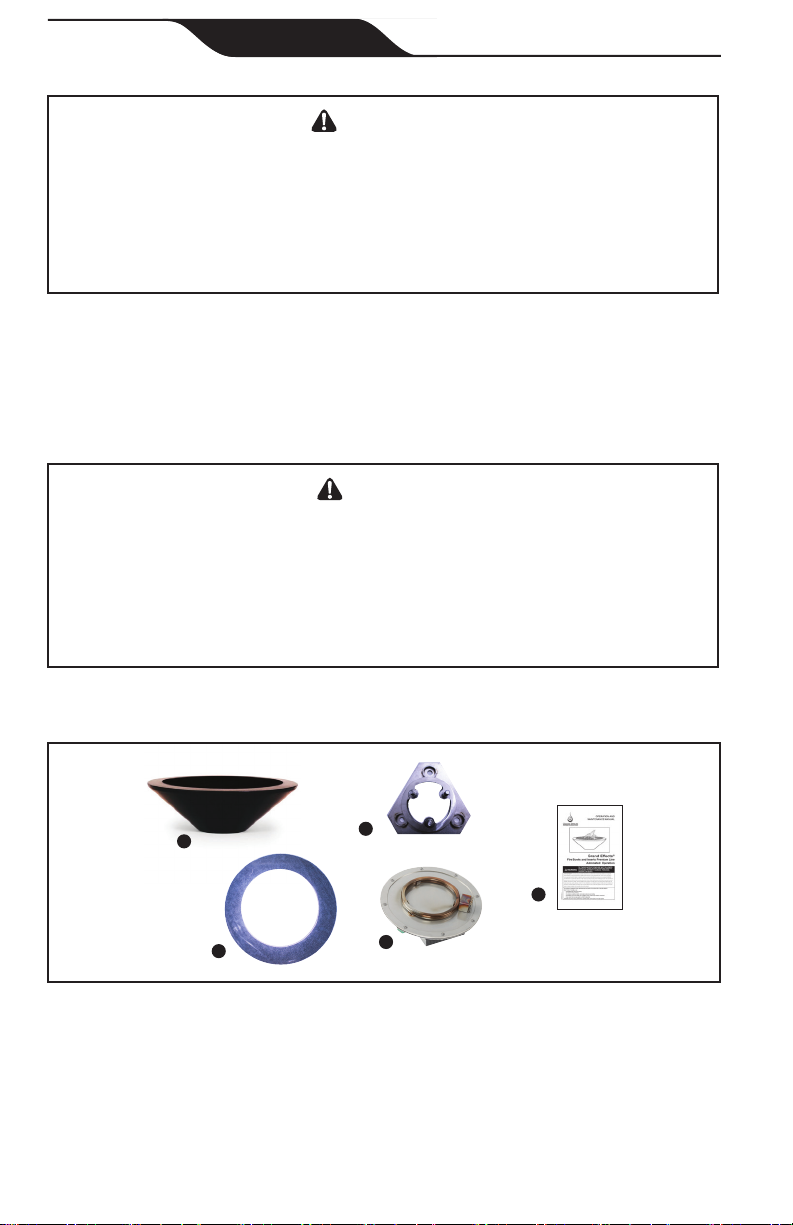
Section 3. Installing the Grand Effects®
Fire Bowls
WARNING
Risk of Electrical Shock or Electrocution. This fire bowl must
be installed by a licensed or certified electrician or a qualified pool
serviceman in accordance with the National Electrical Code®(Canadian
Electrical Code, in Canada) and all applicable local codes and
ordinances. Improper installation will create an electrical hazard, which
could result in death or serious injury to pool or spa users, installers or
others due to electrical shock, and may also cause damage to property.
Always disconnect the power to the bowl at the circuit breaker before
installing or servicing the bowl. Failure to do so could result in death or
serious injury to serviceman, pool or spa users or others due to electrical
shock.
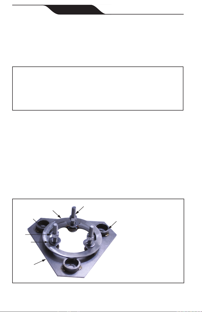
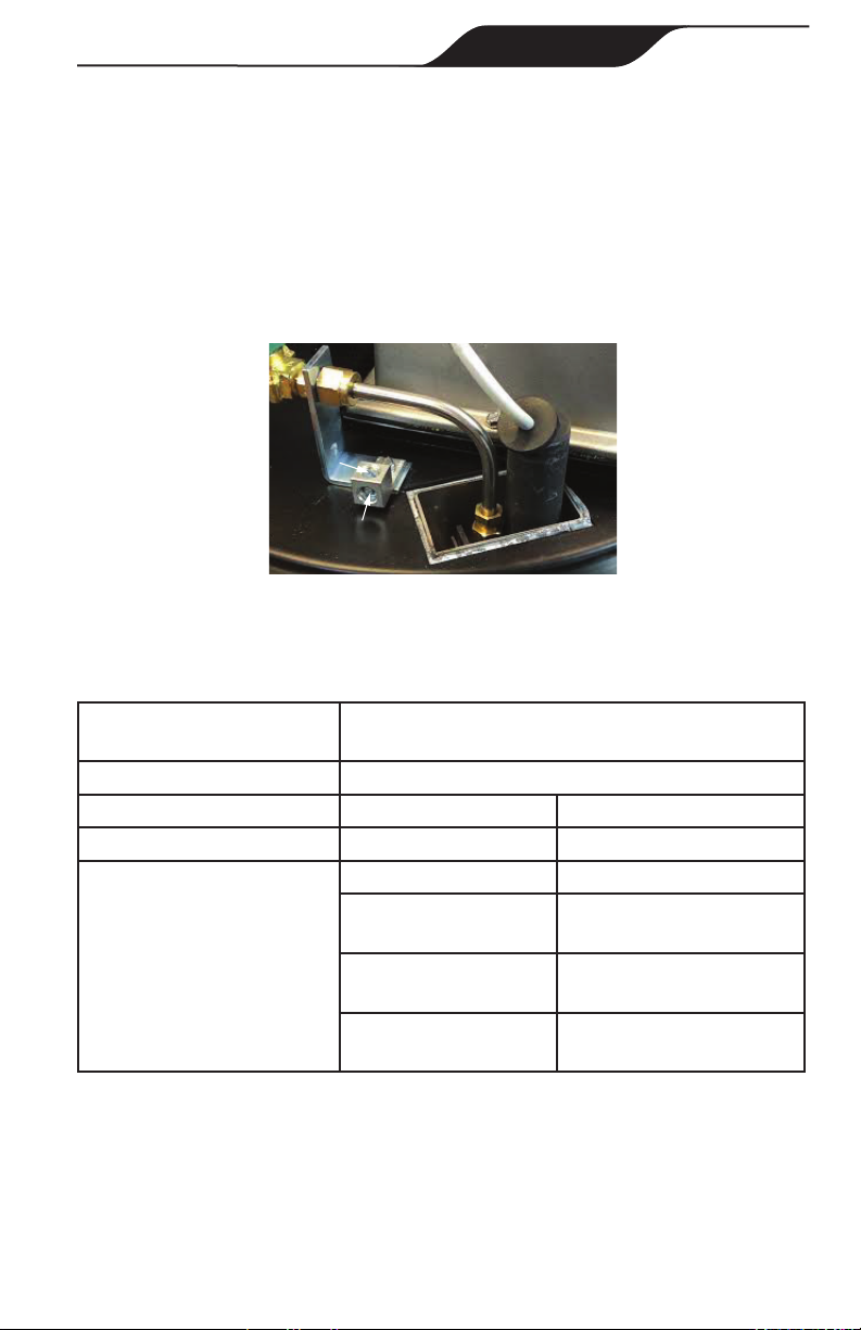
3.1 Preparing the Fire Bowl for Installation
NOTE: The installer must complete preparatory steps before re bowl is
installed.
The National Electrical Code (NEC®) allows listed low-voltage gas fired-
luminaires, decorative fireplaces, fire pits, and similar equipment using low
voltage ignitors that do not require grounding, and are supplied by a listed
transformer / power supply with outputs that do not exceed the low-voltage
contact limit (15 V RMS ac, 30 V continuous dc) to be permitted to be
located less than 1.5 m (5 ft) from the inside walls of the pool.
Metallic equipment, including metallic gas piping, shall be bonded in
accordance with the National Electrical Code in the US, and Canadian
Electrical Code in Canada.
BONDING
In the United States the National Electrical Code® (NEC®) and in Canada
the Canadian Electrical Code (CEC), require that all metallic components
of a pool structure, including reinforcing steel, metal fittings and above
ground components be bonded together (forming an equipotential bonding
grid) with a solid copper conductor not smaller than an 8 AWG (6 AWG in
Canada).