Grandbeing Vision HD SP0104-U01 User manual

Model No.: SP0104-U01
Operating Instructions
Thanks for purchasing our product.
Please be sure to read this instruction manual.
carefully before using our product.


Introduction
SP0104-U01 is a four-way HDMI splitter. It distributes one input HDMI signal to
four identical UTP outputs. These four outputs are synchronized.
SP0104-U01 has the ability of pre-emphasis and equalization. Series connection
of SP0104-U01 achieves long distance transmission of HDMI signal of more
than 50 meters.
SP0104-U01 offers solutions for digital entertainment center, HDTV retail and
show site, HDTV, STB, DVD and Projector factory, noise, space and security
concerns, data center control, information distribution, conference room
presentation, school and corporate training environments.

Contents
HDMI Splitter.........................................................................................1
■Product Overview ...........................................................................1
■Features .........................................................................................1
■Package Contents ..........................................................................3
■Connections and Operations..........................................................3
■Specifications .................................................................................6
■Panel Descriptions .........................................................................7
■Typical Application .........................................................................8
■Maintenance...................................................................................8
■Product Service ..............................................................................8
●Provided Service .........................................................................8
●Mail-In Service ............................................................................9
●Warranty......................................................................................9
●Warranty Limits And Exclusions................................................10

HDMI Splitter
■Product Overview ( Model Number: SP0104-U01 )
Dear customer
Thank you for purchasing this product. For optimum performance and safety,
please read these instructions carefully before connecting, operating or
adjusting this product. Please keep this manual for future reference.
■Features
zEasy to Use: Install in seconds, simple operation.
zDistribution: Four identical UTP outputs.
zHDMI V1.3B.
"Notice
We reserve the right to make changes in the hardware, packaging and any
accompanying documentation without prior written notice.
Page 1

Warning
To reduce the risk of fire, electric shock or product damage:To reduce the risk of fire, electric shock or product damage:
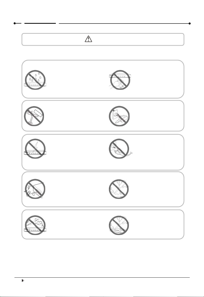
1. Do not expose this apparatus
to rain, moisture, dripping or
splashing and that no objects
filled with liquids, such as vases,
shall be placed on the apparatus.
6. Clean this apparatus
only with dry cloth.
10. Refer all servicing to
qualified service
personnel.
9. Only use attachments /
accessories specified by
the manufacturer.
8. Protect the power cord
from being walked on or
pinched particularly at
p
lu
g
s.
7. Unplug this apparatus
during lightning storms or
when unused for long
periods of time.
5. Do not place sources of naked
flames, such as lighted candles,
on the unit.
4. Do not install near any heat
sources such as radiators, heat
registers, stoves, or other
apparatus (including amplifiers)
that produce heat.
3. To prevent risk of electric
shock or fire hazard due to
overheating, do not obstruct
the unit’s ventilation openings
with newspapers, tablecloths,
curtains, and similar items.
2. Do not install or place this unit
in a bookcase, built-in cabinet or
in another confined space.
Ensure the unit is well ventilated.
Page 2

■Package Contents
① Main unit. P/N_SP0104-U01.
② 5VDC Power Supply.P/N_VDC0503.
③ Operating Insrtuctions.P/N_INSSP0104-U01.
④ IR TX UNIT.
NOTE:Cables are optional
■Connections and Operations
1) Connect the HDMI input sources into SP0104-U01(Input cables are
optional).
2) Connect two CAT-5E/6E cables to both the STP/UTP outputs of
SP0104-U01 and inputs of STP/UTP receiver (such as EX0101-U51/53
etc). Please pay attention to the sequence of the two cables,
CAT5e-1->CAT5e1, CAT5e-2->CAT5e2. (The cable termination must
follow the standard of EIA/TIA 568B, if Single UTP mode, just connect
CAT5E-2).
3) Connect the HDMI output (such as HD-LCD/HD-DLP) into the STP/UTP
receiver.
4) Connect the IR RX receiving cable into STP/UTP receiver IR RX and
connect The IR TX cable into SP0104-U01 IR emitter.
5) Insert the DC side of 5v power supply into SP0104-U01 and then connect
the AC side of the power supply into the wall outlet.
6) Turn on the power.
Attention: DIP Switch EDID setting index
Page 3

Position1 Position2 Position3 Function
0 0 0 1080P stereo (Using Embedded EDID) (note1)
0 0 1 1080P 5.1 (Using Embedded EDID) (note2)
0 1 0
Edid auto mix, mix result is compatible with all HDMI
sinks (note3)
0 1 1
copy the first detected HDMI output's edid to the
input port (note4)
1 0 0
LC mode, 1080P stereo (Using Embedded EDID)
(note5)
1 0 1
LC mode, Edid auto mix, mix result is compatible
with all HDMI sinks (note6)
1 1 0
LC mode, copy the first detected HDMI output's edid
to the input port (note7)
1 1 1 Fix single UTP output (note8)
Note1: The matrix will use the embedded 1080P-stereo EDID when the DIP switch is in this
mode. The EDID will be 1080P video and stereo audio
Note2: The matrix will use the embedded 1080P-5.1 EDID when the DIP switch is in this mode.
The EDID will be 1080P video and 5.1 audio
Note3: The matrix will mix the EDID data of all HDMI sinks. And forward this mixed EDID to
the HDMI source device. The thought of EDID mixing is to enable all the connected sink device
can have video and audio they can output. For example, One TV is 1080P, stereo, another is
1080i, 5.1 audio. The mixed EDID will be 1080i, stereo audio
Note4: Copy the EDID data to the input port. It will copy the EDID data from the first detected
output port
Note5: Please refer to Note1. The only difference is that if video appears noise or interference
when the long HDMI/UTP cable is used or the quality of HDMI/UTP cable is not so good, use
this mode.
Note6: Please refer to Note 3. The only difference is that if video appears noise or interference
when the long HDMI/UTP cable is used or the quality of HDMI/UTP cable is not so good, use
this mode
Page 4

Note7: Please refer to Note 4. The only difference is that if video appears noise or
interference when the long HDMI/UTP cable is used or the quality of HDMI/UTP cable is not so
good, use this mode
Note8: Fix single UTP output, use the embedded 1080P-stereo EDID
Attention: Insert / Extract cables gently.
Page 5

■Specifications
Operating Temperature Range -5 to +35°C (-41 to +95°F)
Operating Humidity Range 5 to 90% RH ( no condensation )
Video Amplifier Bandwidth 140mHz
Input Video Signal 0.5-1.0 volts p-p
Input DDC Signal 5 volts p-p (TTL)
Video Format Supported
VGA:
640x480, 800x600, 1024x768,1 280x1024
DTV/HDTV:
480i/576i/480P/576P/720P/1080i/1080P
3D video support
HDMI Output HDMI 1.3 video and audio (support DTS-HD)
Maximum Transmission
Distance 〉50m ( If needed, HDMI extender is optional )
Power Consumption 8 Watts (max.)
Power Supply 5VDC
Dimensions 175mmL x 115mmW x 40mmH
Mass 0.4 Kgs
Page 6

■Panel Descriptions
Front Panel
Back Panel
Page 7

■Typical Application
■Maintenance
Clean this unit with a soft, dry cloth. Never use alcohol, paint thinner or benzine
to clean this unit.
■Product Service
●Provided Service
1) Damage Requiring service: The unit should be serviced by qualified
service personnel if:
zThe DC power supply cord or AC adaptor has been damaged;
Page 8

zObjects or liquids have gotten into the unit;
zThe unit has been exposed to rain;
zThe unit does not operate normally or exhibits a marked change in
performance;
zThe unit has been dropped or the cabinet damaged.
2) Servicing Personnel: Do not attempt to service the unit beyond that
described in these operating instructions. Refer all other servicing to
authorized servicing personnel.
3) Replacement parts: When parts need replacing ensure the service uses
parts specified by the manufacturer or parts that have the same
characteristics as the original parts. Unauthorized substitutes may result in
fire, electric shock, or other hazards.
4) Safety check: After repairs or service, ask the service to perform safety
checks to confirm that the unit is in proper working condition.
●Mail-In Service
When shipping the unit, carefully pack and send it prepaid, adequately insured
and preferably in the original carton. Include a letter detailing the complaint and
provide a daytime phone and/or email address where you can be reached.
If repair is needed during the limited warranty period the purchaser will be
required to furnish a sales receipt/proof of purchase indicating date of
purchase, amount paid and place of purchase. Customer will be charged for
the repair of any unit received without such proof of purchase.
●Warranty
If your product does not work properly because of a defect in materials or
workmanship,we (referred to as “the warrantor”) will, for the length of the
period indicated as below, (Parts (1) Year, Labor(90) Days)which starts with
the date of original purchase (“Limited Warranty period”), at its option either (a)
Page 9

repair your product with new or refurbished parts, or (b) replace it with a new or
a refurbished product. The decision to repair or replace will be made by the
warrantor.
During the “Labor” Limited Warranty period there will be no charge for labor.
During the “Parts” warranty period, there will be no charge for parts. You must
mail-in your product during the warranty period. This Limited Warranty is
extended only to the original purchaser and only covers product purchased as
new. A purchase receipt or other proof of original purchase date is required for
Limited Warranty service.
●Warranty Limits And Exclusions
1) This Limited Warranty ONLY COVERS failures due to defects in
materials or workmanship, and DOES NOT COVER normal wear and
tear or cosmetic damage. The Limited Warranty ALSO DOES NOT
COVER damages which occurred in shipment, or failures which are
caused by products not supplied by the warrantor, or failures which result
from accidents, misuse, abuse, neglect, mishandling, misapplication,
alteration, faulty installation, set-up adjustments, misadjustment of
consumer controls, improper maintenance, power line surge, lightning
damage, modification, or service by anyone other than a Factory Service
Center or other Authorized Service, or damage that is attributable to acts of
God.
2) There are no express warranties except as listed under “limited
warranty coverage”. The warrantor is not liable for incidental or
consequential damages resulting from the use of this product, or
arising out of any breach of this warranty. (As examples, this excludes
damages for lost time, cost of having someone remove or re-install an
installed unit if applicable, travel to and from the service location, loss of or
damage to media or images, data or other recorded content. The items
Page 10

listed are not exclusive, but are for illustration only.)
3) Parts and service, which are not covered by this limited warranty, are
your responsibility.
Page 11


Table of contents
Other Grandbeing Cables And Connectors manuals
Popular Cables And Connectors manuals by other brands

KanexPro
KanexPro SP-4KPROSLIM1X2 user manual

InEar
InEar Hearmix HM-5 Series user manual

SRS Light Design
SRS Light Design DSR10AB-3 instruction manual

Spector&Co
Spector&Co SpecTech OPHELIA T987 manual

HARTING
HARTING M12-PP-CC-CRIMP-5P-ACOD-M-ANG-SHLD Assembly instruction

Burndy
Burndy Continental thermOweld CS-32 instructions

Amphenol
Amphenol PL183 30 Series Assembly manual

Deutsch
Deutsch HD30 Series Technical manual

Lister
Lister SB 2 instruction manual

Harman
Harman Martin Active Junction Box Power-DMX-Ethernet to... user guide

Renkforce
Renkforce 1362483 operating instructions

Hall Research Technologies
Hall Research Technologies 200A user manual