Granit 50700006 User manual

User Manual
NON-CONTACT INFRARED THERMOMETER
50700006
These operating instructions must be read thoroughly before use and followed carefully.
Please retain these operating instructions for future reference.
Translation of the original operating instructions

Instruction Manual
50700006
2
Table of contents
About these instructions and symbol descriptions .................................................... 3
2Safety information............................................................................................... 3
2.1 General safety instructions ............................................................................. 3
3Important notices ................................................................................................ 3
4Physical appearance ............................................................................................ 4
5LCD screen ......................................................................................................... 5
6Mesurement method ............................................................................................ 6
7Proportion between the distance from probe to object and the diameter of the object to
be measured (D:S) .............................................................................................10
8Emissivity..........................................................................................................11
9Battery replacement ...........................................................................................12
10 Technical parameters..........................................................................................13
11 UKCA Declaration of Conformity ...........................................................................14
12 Disposal ............................................................................................................15
13 Warranty...........................................................................................................15
14 Addresses .........................................................................................................15

Instruction Manual
50700006
3
About these instructions and symbol descriptions
Incorrect operation can lead to serious injury or death.
Incorrect operation or negligence may result in personal injury,
damage to the equipment or faulty measurements.
Instructions and tips for operation.
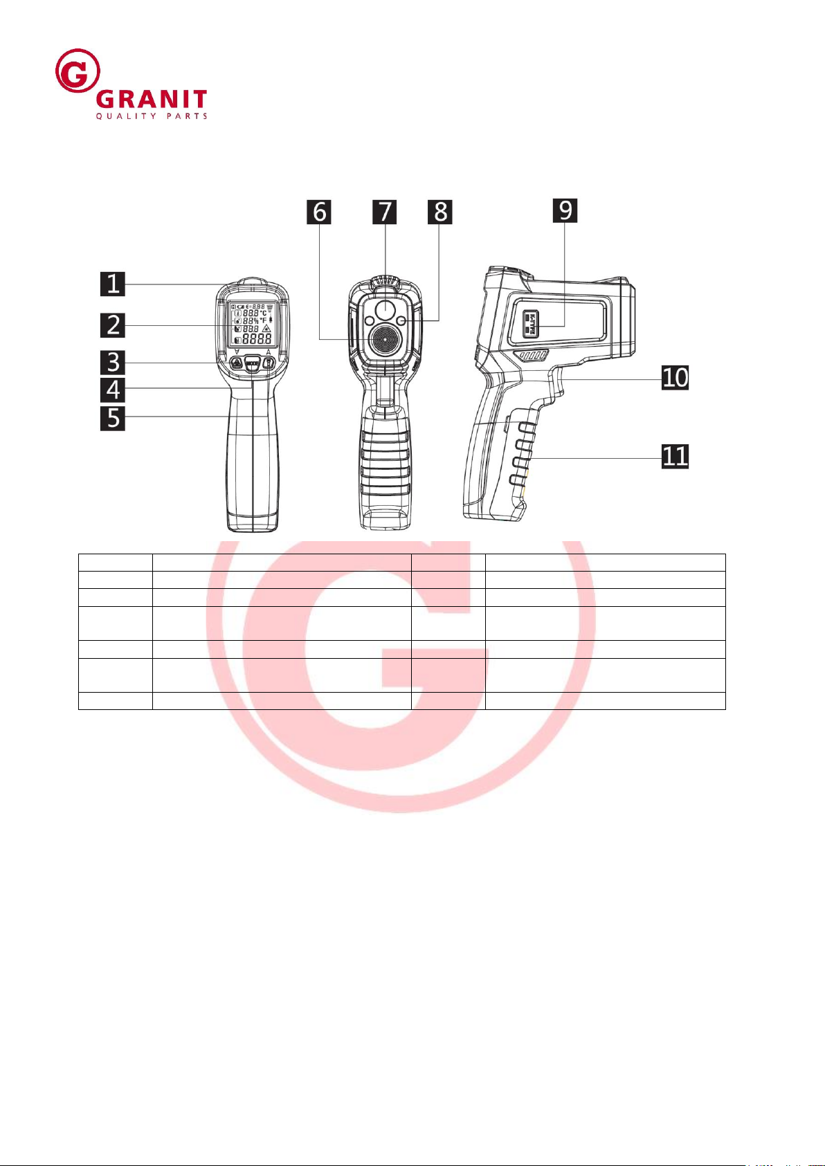
Numbers in the figures (1, 2, 3 ...) refer to the corresponding numbers in brackets
(1), (2), (3) ... in the text next to the item numbers in the tables.
Instructions for which the order must be followed are numbered (1, 2, 3, ...).
Lists are marked with bullet points (●, ●, ...).
2 Safety information
2.1 General safety instructions
•Piease read carefully the Operation Manual before operating the instrument
•Don't cleanse the temperature measuring instrument with any solvent
•Safety symbols
Important notices against hazards:
Compliant with European CE safety directive
This instrument complies with the standards provided below:
EN61326-1
EN60825-1
Laser must be prevented from aligning itself towards human eyes or
reflective surfaces.
3 Important notices
When the working environment experiences a sudden change, the temperature
measurement meter must be placed in an environment for 30 minutes. The
measurement can be resumed only when the temperature inside the meter is
consistent with that outside it.
The electromagnetic field from electric welding and inductive heating must be
minimized
Don't put the temperature measurement meter close to or onto a hot object.
The meter must be kept clean so that dust is denied access to lens cone.

Instruction Manual
50700006
4
4 Physical appearance
Pos.No.
Description
Pos.No.
Description
1
Alarm indicator
7
Laser indicator
2
LCD screen
8
UV
3
Laser control key/numeric
adjustment key
9
K type
4
Mode key
10
Measurement trigger
5
Backlight/UV control key numeric
adjustment key
11
Battery cover
6
Infrared sensor’s sensing area

Instruction Manual
50700006
5
5 LCD screen
Pos.No.
Description
Pos.No.
Description
1
Primary display panel: display the
measured temperature
6
Battery under-voltage indication
2
Functional indication: display Max
PRb (K type probe), E (emissivity)
(adjust the instrument’s
emissivity)
7
Temperature measurement
indication
3
Secondary display panel
8
Data hold
4
Fahrenheit unit
9
Laser enabling indication
5
Celsius unit

Instruction Manual
50700006
6
6 Mesurement method
1. Set the upper limit value for alarms:
Press trigger + mode key to set the status for the instrument switch Mode key to the upper
limit set for an alarm. At this moment, the instrument's functional indication area shows
HAL and secondary display panel the upper limit for an alarm. Press key to increase or
decrease alarm value. A long press on the key will mean rapid increase or decrease in
the set value.
The default alarm value for this instrument is 800°C.
2. Set low alarm value for the instrument
Press trigger + mode key to set the status for the instrument switch Mode key to the low
limit set for an alarm. At this moment, the instrument's functional indication area shows
HAL and secondary display panel the low Iimit for an alarm. Press key to increase or
decrease alarm value. A long press on the key will mean rapid increase or decrease in
the set value. The default alarm value for this instrument is -50°C.

Instruction Manual
50700006
7
3. Set the emissivity for the instrument
Press trigger + mode key to set the emissivity for the instrument, switch Mode key to the
low limit set for an alarm. At this moment, the instrument's functional indication area shows
and secondary display panel the emissivity for an alarm. Press key to increase or
decrease emissivity value. A long press on the key will mean rapid increase or
decrease in the set value.

Instruction Manual
50700006
8
4. Set the temperature unit fur the instrument
Press the Mode key for 2 seconds to switch the temperature measurement unit.
5. Enable/disable Laser
Press key to enable or disable laser.
The instrument will display the symbol for laser
6. Turn on or off UV
Press key to turn on or off UV (only PM6530C). Leak detection:
The Leakage of verhicle air conditioning and other high pressure systems can be detected
quickly by ultraviolet. Flourescent agent is injected into the air condition system, fluorescent
agent will with the refrigerant in the air-conditioning system in circulation, when the air
conditioning system has a leak, fluorescent agent will left leakage Fluorescence leakage
under theirradiation of ultraviolet light can emit fluorescence at, and then find the leak.
7. Non-contact temperature measurement
Target the temperature measurement meter at an object and pull the trigger for a period to
carry out continuous measurement of temperature. After display becomes stable, release
the trigger to hold measurement result.
When the trigger is pressed, the instrument’s secondary display
panel will first show the set emissivity and then display the
measured maximum temperature.

Instruction Manual
50700006
9
When the measured value is greater than ambient environment + HAL value or less than
the ambient environment + LAL value, the red indicator of the instrumentwill be on to
sound an alarm .Otherwise, the green indicator will be on.
8. K-type Temperaturemeasurement
After K type thermocouple probe is inserted into the thermocouple socket of the instrument,
the instrument's functional indication area will display PRb and secondary display panel the
temperature value of K thermocouple.

Instruction Manual
50700006
10
7 Proportion between the distance from probe to object
and the diameter of the object to be measured (D:S)
Temperature measurement meter has a certain angle and field of vision, as shown in the
diagram below:
It must be ensured that the object to be measured is fully within the field of vision afforded
by the temperature measurement meter, that is, the meter can see nothing but the object
to be measured. The greater the object to be measured is, the farther the distance detected
by the meter may be. The smaller the object is, the shorter the distance to be measured
must be. The proportion between the distance to be measured and the size of the object to
be measured (D:S) is 12:1, as shown in the diagram below.
While measuring an object, the instrument will emit an indicative ring. The measured
temperature of the surface is the internal temperature of the ring.
The object to
be measured
Lens con
Photosensitive element

Instruction Manual
50700006
11
8 Emissivity
Emissivity refers to the ability of an object to emit infrared ray. The greater the emissivity
is, the stronger the emission ability of the surface of an object is. The emissivity of most
organic substances or oxidized surfaces of metals falls within the range of 0.85~0.98. The
default emissivity of this measurement device is 0.95. The instrument’s emissivity is set to
be consistent with that of the object to be measured at the moment of measurement. The
effect of emissivity on measurement result must be noticed at the time of measurement.
The diagram provided below is a reference table for emissivity.
Surface measured
Emissivity
Aluminum Metal
Oxidized
0.2~0.4
A3003AlloyOxidized
0.3
A3033AlloyRough
0.1~0.3
Brass
Polished
0.3
Oxidized
0.5
Copper
Oxidized
0.4~0.8
Electronic terminal board
0.6
Hastelloy
0.3~0.8
Chromium-
Nickel-Iron Alloy
Oxidized
0.7~0.95
Sandblast
0.3~0.6
Electro-Polished
0.15
Iron
Oxidized
0.5~0.9
Rusted
0.5~0.7
Iron (Cast)
Oxidized
0.6~0.95
No Oxidized
0.2
Melt & cast
0.2~0.3
Iron(Forged) Passivated
0.9
Lead
Rough
0.4
Oxidized
02~0.6

Instruction Manual
50700006
12
Surface measured
Emissivity
Mo Oxidized
0.2~0.6
Nickel Oxidized
0.2~0.5
Platinum Black
0.9
Steel
Cold rolled
0.7~0.9
Sanding plate
0.4~0.6
Polished plate
0.1
Zinc
Oxidized
0.1
Asbestos
0.95
Asphalt
0.95
Basalt stone
0.7
Carbon
08~0.9
Non-oxidized
0.7~0.8
Graphite
0.9
Silicon Carbide
0.95
Clay
0.95
Concrete
0.95
Fabric
0.95
Glass plate
0.85
Sand-gravel
0.95
Gypsum
08~0.95
Ice
0.98
Limestone
0.98
Paper
0.95
plastic
0.95
Soil
0.9~0.98
Water
0.93
Wood (natural)
0.9~0.95
9 Battery replacement
When the battery’s power is low, the battery symbol indicator will be on. At such
moment, you must replace the existing battery. What you need to do is to open the battery
cover and replace the old battery with a new 9V battery. Refer to the diagram below:

Instruction Manual
50700006
13
10 Technical parameters
LCD
Color LCD
D:S
12:1
Emissivity
0.10~1.00
Respone spectrum
8~14 μm
Laser
<1mW /630-670nm Level 2
Response time
<0.5S
Automatic shutdown
15 seconds
Operational temperature
0~40 °C
Storage temperature
-10°C ~ 60°C
Power
9V 6F22 batery
UV
Yes
K-type
-50°C ~ 800°C (-58°F ~ 1472°F)
Measurement range (Non-contact
temperature measurement)
-50°C~0°C ± 3°C
0~800°C ± (1.5% reading +2°C/4°F)
Precision (non-contact temperature
measurement)
-40°C~1000°C (-40°F~1832°F) ± (1.5%
reading+ 2°C/4°F)

Instruction Manual
50700006
14
11 UKCA Declaration of Conformity
The manufacturer,
Wilhelm Fricke SE
Zum Kreuzkamp 7
DE-27404 Heeslingen
declares under their sole responsibility that the cordless drill driver
Type/series identification: 50700006
conforms to the provisions of
Electromagnetic Compatibility Regulations 2016
The Restriction of the Use of Certain Hazardous Substances in Electrical and
Electronic Equipment Regulations 2012
The product was developed in accordance with the following standards:
EN 55032:2015
EN 55035:2017
Authorised person for documentation:
Mr Eike Viebrock
Wilhelm Fricke SE
Zum Kreuzkamp 7
DE-27404 Heeslingen
The serial number and model year are shown on the type plate of the equipment.
Heeslingen, 10.11.2022
Original UKCA Declaration of Conformity
__________________________________
Holger Wachholtz, board

Instruction Manual
50700006
15
12 Disposal
The separate, environmentally friendly disposal of materials encourages recycling of
materials. Therefore, after expiry of the normal service life, the equipment itself and all related
components, including the lubrication, packaging and wear parts, should be disposed of at a
recyclables collection point.
Packaging, equipment and accessories are made of recyclable materials and should be
disposed of accordingly. If the unit is no longer serviceable, make sure it is unusable before
disposal. If you do not have the necessary expertise, engage a specialist for dismantling and
disposal. INJURY HAZARD!
!!! Always observe local disposal regulations!!!
13 Warranty
The warranty terms of Wilhelm Fricke SE, as can be found in the sales documents and the
current version of the Terms and Conditions, apply.
In case of questions, please contact the company’s customer service line.
14 Addresses
Sales/customer service/ Tel.: +49 (4281) 712 712
Spare parts sales: Fax: +49 (4281) 712 700
Postal and shipping address: Wilhelm Fricke SE
Zum Kreuzkamp 7
DE-27404 Heeslingen
Legal notice
Translation of the original operating instructions for Non-contact Infrared Thermometer 50700006
Manufacturer: Wilhelm Fricke SE - DE-27404 Heeslingen
Version 1, August 2022
©2022 Wilhelm Fricke SE
Reproduction in whole or in part is prohibited without the written consent of the Wilhelm Fricke SE company.
All product names mentioned in these operating instructions are trademarks of their respective companies.
Printed on paper made from chlorine and acid-free bleached pulp.
Table of contents