Grant MonoWave Series User guide

UK | DOC 0134 | Rev 1.0 | September 2020
Grant MonoWave System
Indirect HP (Heat Pump) Cylinder
Installation, Servicing and User Instructions

GRANT ENGINEERING (UK) LIMITED
Hopton House, Hopton Industrial Estate, Devizes, Wiltshire, SN10 2EU
Tel: +44 (0)1380 736920 Fax: +44 (0)1380 736991
This manual is accurate at the date of printing but will be superseded and should be disregarded if specications and/or appearances are changed in the interests of continued product improve-
ment. However, no responsibility of any kind for any injury, death, loss, damage or delay however caused resulting from the use of this manual can be accepted by Grant Engineering (UK)
Limited, the author or others involved in its publication.
All good sold are subject to our ocial Conditions of Sale, a copy of which may be obtained on application.
© Grant Engineering (UK) Limited. No part of this manual may be reproduced by any means without prior written consent.
IMPORTANT NOTE FOR INSTALLERS
These instructions are intended to guide Installers on the
installation, commissioning and servicing of the Grant MonoWave
indirect HP (heat pump) cylinder. After installing the cylinder, leave
these instructions with the user.
User instructions to guide users in the operation of the cylinder
are in Section 12 of these instructions.
SPECIAL TEXT FORMATS
The following special text formats are used in these instructions
for the purposes listed below:
! WARNING !
Warning of possible human injury as a consequence of not
following the instructions in the warning.
! CAUTION !
Caution concerning likely damage to equipment or tools
as a consequence of not following the instructions in the
caution.
! NOTE !
Used for emphasis or information not directly concerned
with the surrounding text but of importance to the reader.
PRODUCT CODES COVERED
Grant MonoWave indirect HP
Cylinder Model
Product Code
'A rated' 200 litre HPMONOA/IND200
125 litre HPMONO/IND125
150 litre HPMONO/IND150
170 litre HPMONO/IND170
200 litre HPMONO/IND200
250 litre HPMONO/IND250
300 litre HPMONO/IND300
400 litre HPMONO/IND400
Slimline 200 litre HPMONO/IND200/SL
Slimline 250 litre HPMONO/IND250/SL
Slimline 300 litre HPMONO/IND300/SL
SERVICING
The cylinder should be serviced at least every twelve months and
the details entered in the Benchmark Book.

1 INTRODUCTION 4
1.1 Installation requirements 4
1.2 Water supply requirements 4
1.3 Location 4
1.4 Storage and handling 4
1.5 About your cylinder 4
1.6 Open vented hot water systems 4
1.7 Primary circuit pipework 4
connections
1.8 Cylinder by-pass 4
1.9 Secondary circuit pipework 5
connections
1.10 Taps and ttings 5
1.11 Hard water scaling 5
1.12 Insulation 5
1.13 Health and Safety 5
2 TECHNICAL DATA 6
2.1 Cylinder technical data 6
2.2 Product contents 8
2.3 Dimensions 9
2.4 Connections and Controls 14
3 PRIMARY CIRCUIT INSTALLATION 17
3.1 Grant Monowave HP cylinders 17
with buer
3.2 Primary connections 17
3.3 The 2-Port Valve 17
3.4 Hard Water Areas 17
4 SECONDARY CIRCUIT INSTALLATION 18
4.1 General 18
4.2 Cold Water Inlet Manifold 18
4.3 Installation 18
4.4 Expansion Vessel 19
4.5 Temperature and Pressure Relief 19
Valve
4.6 Hot water Supply 19
4.7 Prevention of Scaling 19
4.8 Secondary Return 19
4.9 Tundish 20
4.10 Discharge Pipe 20
4.11 Discharge Pipe Sizing 20
4.12 Worked Example 20
4.13 Discharge Pipe Arrangement 21
5 ELECTRICAL 22
5.1 Immersion Heater 22
5.2 Immersion Heater Wiring Instructions 22
5.3 Immersion Heater Safety Cut-Out 23
5.4 Dual Thermostat 23
5.5 2-Port Valves 23
5.6 Heat pump interface box 23
5.7 "S Plan" Schematic and Wiring 24
Diagrams
Contents Page 3
6 COMMISSIONING, DRAINING DOWN 27
AND SAFETY
6.1 Filling the Cylinder 27
6.2 Draining Down 27
6.3 Immersion Heater Safety Cut-Out 27
6.4 Cold Water Discharge from Tundish 28
6.5 Hot Water Discharge from Tundish 28
6.6 Expansion Vessel 28
6.7 Setting the Cylinder By-Pass 28
6.8 Customer Handover 28
7 MAINTENANCE 29
7.1 Servicing and Maintenance 29
7.2 Inlet Manifold Assembly 29
7.3 Expansion Relief Valve Cartridge 29
7.4 Expansion Vessel 29
8 FAULT FINDING 30
8.1 Intermittent Water Discharge 30
8.2 Constant Water Discharge 30
8.3 No Flow from Hot Water Taps 31
8.4 Cold Water Flow from Hot Water 31
Taps
8.5 Excessive Hot Water from Taps 32
9 SPARE PARTS 33
9.1 Spare Parts 33
10 PRODUCT FICHE 34
11 END OF LIFE INFORMATION 34
12 USER INSTRUCTIONS 35
12.1 User Instructions 35
13 GUARANTEE 36
CONTENTS

Section 1: IntroductionPage 4
1.1 INSTALLATION REQUIREMENTS
Thank you for purchasing a Grant unvented hot water storage
cylinder from our Wave range.
These Installation and User instructions must be read carefully
before you begin installing the cylinder.
The cylinder must be installed by a competent person in
compliance with all current legislation, codes of practice and
local by-laws covering the installation of an unvented hot water
cylinder.
Please also make sure that the installation complies with the
information contained in these Installation and User Instructions.
To prevent damage to the coil, cylinder and cylinder connections,
make any soldered joints before connecting pipework to the
cylinder.
1.2 WATER SUPPLY REQUIREMENTS
We recommend that your Grant unvented cylinder is installed with
an uninterrupted water supply.
Where possible, the unit should be fed via a Ø22 mm supply pipe.
It requires a supply pressure of at least 1.5 bar with a ow rate of
at least 20 litres per minute as a minimum for it to function.
Even with this pressure and ow rate, the ow from the outlets
will be disappointing if several outlets are used simultaneously.
Generally speaking, the higher the supply pressure, the better the
system will function.
The cylinder control equipment is factory set to limit the incoming
system operating pressure to 3 bar. The maximum supply
pressure into the pressure reducing valve (PRV) is 12 bar.
1.3 LOCATION
The unit is designed to be oor standing, vertically mounted,
internally in a frost-free environment. When choosing a suitable
location for the cylinder, consideration should be given to the
routing of the discharge pipe to a convenient point and also
the availability of an adequate power supply for connecting the
immersion heater(s).
The cylinder may stand on any at and level surface without any
special foundation requirements, provided that it is suciently
robust to support the full weight of the cylinder (refer to Section
2.1).
The position of the cylinder should be such that easy access is
provided for servicing the controls and replacing the immersion
heater(s) should the need arise.
Generally, pipe runs should be made as short as possible and
lagged to prevent heat loss.
1.4 STORAGE AND HANDLING
If the cylinder is not being installed immediately, it should remain
in its carton to prevent damage. We recommend that the cylinder
be transported to its installation position on a sack truck or similar
whilst still within the carton.
! CAUTION !
Do not use the Temperature and Pressure relief valve (T&P
relief valve) as a handle when moving and positioning the
cylinder.
1.5 ABOUT YOUR CYLINDER
Gant MonoWave indirect HP cylinders have a single coil designed
for connection to an air source heat pump, such as the Grant
Aerona³ range. If a source such as Solar Thermal or another
make of heat pump is to be connected, please refer to the
manufacturer’s installation instructions for more information.
The coil must be connected using a 2-port motorised valve (for
solar installations a high temperature 2-port or solenoid valve
must be used) to shut o the ow from the primary source and
electronically interlocked with the heat source via the cylinder
control and high limit thermostat. This valve is supplied loose with
all Grant MonoWave indirect HP cylinders.
Failure to t this 2-port valve will invalidate all guarantees and will
be in breach of the Building Regulations Approved Document G3
(2010). More information on electrical wiring is given in Section 5
of these instructions.
MonoWave indirect HP cylinders are factory-tted with a
temperature and pressure relief (T&P) valve and a 3kW electric
immersion heater (two immersion heaters are supplied with the
300 and 400 models).
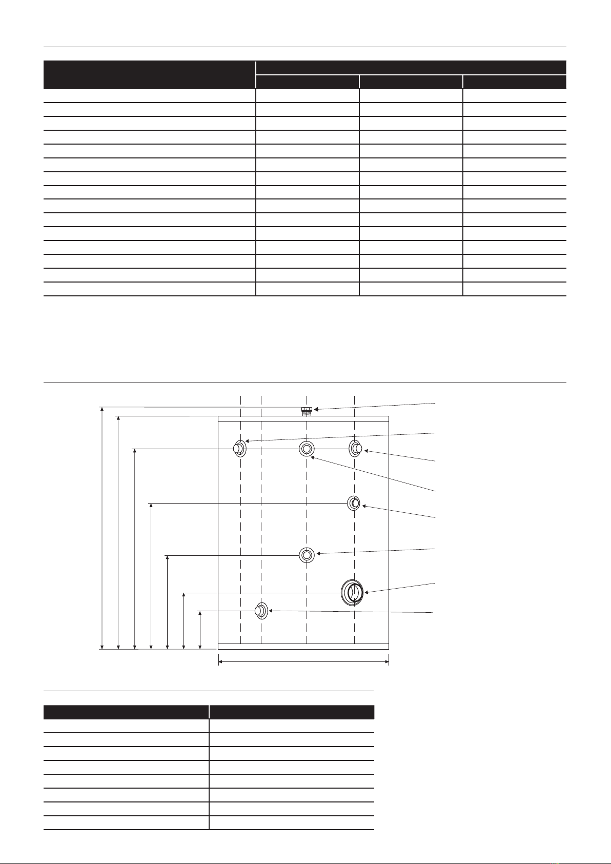
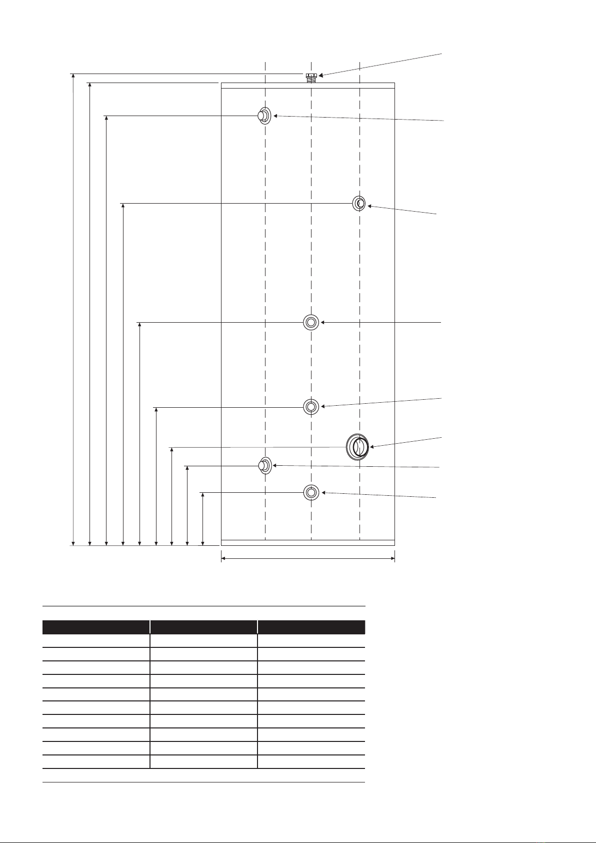
Refer to Figures 2-6 to 2-10 and their corresponding tables for the
T&P valve position.
Refer to Sections 5, 6 and 12 for further details on immersion
heaters.
1.6 OPEN VENTED HOT WATER SYSTEMS
If required, your MonoWave indirect HP cylinder can be used
as part of an open vented hot water system, i.e. fed from a cold
water storage cistern and tted with an open vent pipe, provided
the maximum head does not exceed 30 metres.
When used in this way, it will not be necessary to install the
expansion vessel and cold water inlet manifold supplied with the
cylinder.
! NOTE !
The temperature and pressure relief (T&P) valve must be
left connected to the cylinder (as supplied).
As it may still operate due to temperature, it should be connected
in the correct manner - refer to guidance given in Section 4 of
these instructions.
1.7 PRIMARY CIRCUIT PIPEWORK
CONNECTIONS
All primary circuit pipework connections to the cylinder MUST
be made in accordance with Figures 2-6 to 2-10 as appropriate.
Refer to Section 3 (Primary Circuit Installation) for further details.
1.8 CYLINDER BY-PASS
When either a Grant Aerona³ HPID13R32 (13kW) or HPID17R32
(17kW) heat pump is used with this cylinder, a simple by-pass
MUST be tted between the primary ow and return pipes at the
cylinder. This by-pass consists of a 22 mm pipe tted between the
primary ow and return pipes tted with a 22 mm gate valve.
This by-pass must be set during commissioning. Refer to Section
6.7 of these Installation and User Instructions.
! NOTE !
A by-pass at the cylinder, as described above, is NOT
required for the Grant Aerona³ HPID6R32 (6kW) or
HPID10R32 (10kw) heat pumps, but ONLY when a Grant
Aerona³ HPID13R32 (13kW) or HPID17R32 (17kW) heat
pump is used with this cylinder.
1 INTRODUCTION

Section 1: Introduction Page 5
1.9 SECONDARY CIRCUIT PIPEWORK
CONNECTIONS
All secondary circuit primary pipework connections to the cylinder
MUST be made in accordance with Figures 2-6 to 2-10 as
appropriate. Refer to Section 4 (Secondary Circuit Installation).
1.10 TAPS AND FITTINGS
All taps and ttings incorporated in the unvented hot water system
should have a rated operating pressure of 7 bar or above.
1.11 HARD WATER SCALING
If the cylinder is used in a hard water area scaling will form
inside the cylinder and this will reduce both the performance and
working life of the cylinder.
Where the total hardness exceeds 125 ppm a high capacity water
softener, or suitable water conditioner, should be installed in the
incoming cold water supply to the cylinder.
It is recommended that the water temperature control thermostats
(on the immersion heaters and dual thermostats) tted to the
cylinder be set no higher than 60°C. This will help reduce the
migration of suspended solids in the water and help minimise the
build-up of lime scale.
1.12 INSULATION
All Grant MonoWave Cylinders are insulated with CFC/HFC free,
re retardant, polyurethane foam injected between the stainless
steel cylinder and the outer casing. This polyurethane foam has
a Global Warming Potential (GWP) of less than 3 and an Ozone
Depletion Potential (ODP) of 0.
All regular diameter models (except the 'A rated' cylinder) are
insulated with a 40mm layer of this polyurethane foam.
The 'A rated' MonoWave cylinder is insulated with a 90mm layer
of this polyurethane foam.
The Slimline range of MonoWave cylinders are insulated with a
30mm layer of this polyurethane foam.
1.13 HEALTH AND SAFETY
The information supplied in Tables 2-1 and 2-2 will help you
assess the safest way to manoeuvre your cylinder into position.
Please use the correct table to nd the empty weight of your
cylinder and then consider how you can safely move it into its nal
position.
Please leave these Installation and User Instructions with the
householder after installation.

2.1 CYLINDER TECHNICAL DATA
2.1.1 REGULAR DIAMETER MODELS
Table 2-1: Cylinder technical data (regular diameter models)
MonoWave Indirect HP Cylinders
Standard eciency A rated
125 litre 150 litre 170 litre 200 litre 250 litre 300 litre 400 litre 200 litre
Nominal capacity (litres) 125 150 170 200 250 300 400 200
Actual capacity (litres) 118 136 165 188 222 274 356 202
Overall diameter (mm) 580 580 580 580 580 580 580 580
Overall height (mm) 830 920 1,070 1,192 1,395 1,685 2,085 1,935
Weight - empty (kg) 30 32 45 49 59 68 76 70
Weight - full (kg) 155 182 215 249 309 368 476 270
Secondary return connection (mm) 22 22 22 22 22 22 22 22
Cold feed / hot draw-o connections (mm) 22 22 22 22 22 22 22 22
Primary coil connections (mm) 22 22 22 22 22 22 22 28
Primary coil length (m) 11.68 8.00 8.00 16.00 16.00 16.00 16.00 16.00
Primary coil surface area (m²) 1.5 1.65 1.65 3.3 3.3 3.3 3.3 3.3
Primary coil pipe diameter (mm) 28 32 32 32 32 32 32 32
Maximum water supply pressure (bar) 12 12 12 12 12 12 12 12
System operating pressure - pre-set (bar) 3 3 3 3 3 3 3 3
Expansion vessel charge pressure (bar) 3 3 3 3 3 3 3 3
Expansion relief valve pressure (bar) 6 6 6 6 6 6 6 6
T&P relief valve lift pressure (bar) 7 7 7 7 7 7 7 7
T&P relief valve lift temperature (°C) 90 90 90 90 90 90 90 90
Maximum primary circuit working pressure (bar) 3 3 3 3 3 3 3 3
Performance:
Primary coil rating (kW) 24.0 27.8 27.8 47.0 47.0 56.6 56.6 47.0
Standing heat loss (kWh/24hrs)* 1.48 1.72 1.92 2.04 2.16 2.32 2.58 1.01
ERP rating CCCBC C C A
* Test carried out at 60°C.
Section 2: Technical DataPage 6
2 TECHNICAL DATA

Section 2: Technical Data Page 7
2.1.2 SLIMLINE MODELS
Table 2-2: Cylinder technical data (slimline models)
Slimline MonoWave Indirect HP Cylinders
200 litre 250 litre 300 litre
Nominal capacity (litres) 200 250 300
Overall diameter (mm) 510 510 510
Overall height (mm) 1,538 1,865 2,055
Secondary return connection (mm) 22 22 22
Cold feed / hot draw-o connections (mm) 22 22 22
Primary coil connections (mm) 22 22 22
Primary coil length (m) 16.00 16.00 16.00
Primary coil surface area (m²) 3.3 3.3 3.3
Primary coil pipe diameter (mm) 32 32 32
Maximum water supply pressure (bar) 12 12 12
System operating pressure - pre-set (bar) 3 3 3
Expansion vessel charge pressure (bar) 3 3 3
Expansion relief valve pressure (bar) 6 6 6
T&P relief valve lift pressure (bar) 7 7 7
T&P relief valve lift temperature (°C) 90 90 90
Maximum primary circuit working pressure (bar) 3 3 3
Performance:
Primary coil rating (kW) 47.0 47.0 56.6

Section 2: Technical DataPage 8
2.2 PRODUCT CONTENTS
2.2.1 REGULAR DIAMETER MODELS
Table 2-3: Product contents (regular diameter models)
Standard eciency A rated
125 litre 150 litre 170 litre 200 litre 250 litre 300 litre 400 litre 200 litre
Cylinder assembly - 125 litre 1-------
Cylinder assembly - 150 litre - 1 - - - - - -
Cylinder assembly - 170 litre - - 1 - - - - -
Cylinder assembly - 200 litre ---1----
Cylinder assembly - 250 litre ----1---
Cylinder assembly - 300 litre - - - - - 1 - -
Cylinder assembly - 400 litre - - - - - - 1 -
Cylinder assembly - A rated 200 litre -------1
Expansion vessel - 12 litre 1 1 - - - - - -
Expansion vessel - 19 litre* - - 1 1 - - - 1
Expansion vessel - 24 litre* - - - - 1 1 - -
Expansion vessel - 35 litre** - - - - - - 1 -
Expansion vessel hose (¾” BSPF x ¾” BSPM) c/w washer 11111111
Adapter (22mm compression x 3/4” BSPM) - - 1* 1* 1* 1* -1*
Adapter (1" BSPF x 3/4" BSPM) ------1** -
Expansion vessel wall bracket and band 1 1 1 1 1 1 1 1
½ʺ temperature and PRV - 7 bar/90°C † 11111111
Tundish - 15/22 mm 11111111
Drain cock - ½ʺ end feed 11111111
Inlet manifold - 3 bar PRV and 6 bar expansion relief valve 1 1 1 1 1 1 1 1
2-port motorised valve - 22 mm 1 1 1 1 1 1 1 1
Dual thermostat (control: 25-65°C / high limit: 90°C) 11111111
Immersion heater - 3kW 1¾ʺ boss † 11111221
† Factory tted
* Vessel may come with:
• a 3/4” BSPM thread allowing for direct connection to the supplied expansion vessel hose.
OR
• a 22mm compression tting.
In this instance, a 22mm compression to 3/4” BSPM adapter will be supplied, for connection to the supplied expansion vessel hose.
A short length of 22mm pipe will need to be sourced and tted between the 22mm compression ttings at the vessel and the expansion vessel
hose adapter.
** 35 litre expansion vessels are supplied with a 1" BSPM connection, meaning an adapter (supplied) is required for connection to the supplied
expansion vessel hose.

Page 9Section 2: Technical Data
2.2.2 SLIMLINE MODELS
Table 2-4: Product contents (slimline models)
Slimline models
200 litre 250 litre 300 litre
Cylinder assembly - 200 litre 1 - -
Cylinder assembly - 250 litre - 1 -
Cylinder assembly - 300 litre - - 1
Expansion vessel - 19 litre* 1 - 1
Expansion vessel - 24 litre* - 1 1
Expansion vessel hose (¾” BSPF x ¾” BSPM) c/w washer 111
Adapter (22mm compression x 3/4” BSPM) 1* 1* 1*
Expansion vessel wall bracket and band 1 1 1
½ʺ temperature and PRV - 7 bar/90°C † 111
Tundish - 15/22 mm 111
Drain cock - ½ʺ end feed 111
Inlet manifold - 3 bar PRV and 6 bar expansion relief valve 1 1 1
2-port motorised valve - 22 mm 1 1 1
Dual thermostat (control: 25-65°C / high limit: 90°C) 111
Immersion heater - 3kW 1¾ʺ boss † 112
† Factory tted
* Vessel may come with:
• a 3/4” BSPM thread allowing for direct connection to the supplied expansion vessel hose.
OR
• a 22mm compression tting.
In this instance, a 22mm compression to 3/4” BSPM adapter will be supplied, for connection to the supplied expansion vessel hose.
A short length of 22mm pipe will need to be sourced and tted between the 22mm compression ttings at the vessel and the expansion vessel
hose adapter.
Dia
ABCDE
22mm Hot water
draw off
½" T & P Relief
valve (factory fitted)
22mm Secondary
return
22mm Cold water
inlet
Immersion heater
(factory fitted)
Heat pump stat
pocket
F
Heat pump flow
(22mm)
Heat pump return
(22mm)
G
Table 2-5: MonoWave indirect HP cylinder dimensions (125L model only)
Dimensions (mm) 125 litre
A 215
B 230
C355
D 465
E 585
F 795
G 830
Dia 580
2.3 DIMENSIONS
Figure 2-1: MonoWave indirect HP cylinder dimensions (125L model only)

Section 2: Technical DataPage 10
Dia
ACDEF*GH
˚93 22mm Hot water
draw off
1/2" T & P Relief
valve (factory fitted)
Heat pump flow
(22mm)
22mm Secondary
return
22mm Cold water
inlet
Immersion heater
(factory fitted)
Heat pump stat
pocket
0˚39˚
B
I
Heat pump return
(22mm)
Figure 2-2: MonoWave indirect HP cylinder dimensions (150 and 170L models only)
Table 2-6: MonoWave indirect HP cylinder dimensions (150 and 170L models only)
Dimensions (mm) 150 litre 170 litre
A 200 200
B 215 215
C230 230
D 341 355
E 620 620
F* 490 705
G 675 835
H 885 1035
I 920 1070
Diameter 580 580
* Secondary return is below heat pump ow tapping on 150L model ONLY

Page 11
Figure 2-3: MonoWave indirect HP cylinder dimensions (excluding 125, 150 and 170L models)
Table 2-7: MonoWave indirect HP cylinder dimensions (excluding 125, 150 and 170L models)
Dimensions (mm) 200 litre 250 litre 300 litre 400 litre
A 215 215 215 215
B 230 230 230 230
C355 355 515 415
D 930 950 950 950
E - - 1050 1050
F* 800 1050 1395 1555
G 930 1140 1440 1862
H 1157 1360 1650 2050
I 1192 1395 1685 2085
Diameter 580 580 580 580
* Secondary return is below ow and return tappings on 200L model ONLY
Dia
ACDEF*GH
˚93 22mm Hot water
draw off
1/2" T & P Relief
valve (factory fitted)
Heat pump flow
(22mm)
Heat pump return
(22mm)
22mm Secondary
return
Immersion heater
(factory fitted) on
300 & 400
models only
22mm Cold water
inlet
Immersion heater
(factory fitted)
Heat pump stat
pocket
0˚39˚
B
I
Section 2: Technical Data

Dia
A
BC
EFGH
˚03˚04 22mm Hot water
draw off
1/2" T & P Relief
valve (factory fitted)
Heat pump flow
(28mm)
Heat pump return
(28mm)
22mm Secondary
return
22mm Cold water
inlet
Immersion heater
(factory fitted)
Stat pocket
0˚30˚
Stat pocket
D
I
Figure 2-4: 'A-rated' MonoWave indirect HP cylinder dimensions
Table 2-8: 'A-rated' MonoWave indirect HP cylinder dimensions
Dimensions (mm) 'A-rated'
200 litre
A 153
B 183
C663
D 803
E 903
F 1288
G 1573
H 1900
I 1935
Diameter 580
Section 2: Technical DataPage 12

Section 2: Technical Data Page 13
Dia
A
BC
FGHI
˚34 22mm Hot water
draw off
½" T & P Relief
valve (factory fitted)
Heat pump flow
(22mm)
Heat pump return
(22mm)
22mm Secondary
return
22mm Cold water
inlet
Immersion heater
(factory fitted)
Stat pocket
0˚43˚
D
E
Immersion heater
(factory fitted)
300 model only
Table 2-9: Slimline MonoWave indirect HP cylinder dimensions
Dimensions (mm) 200 litre 250 litre 300 litre
A 186 186 186
B 201 201 201
C356 356 356
D 821 821 821
E - - 991
F 1121 1471 1671
G 1321 1621 1821
H 1503 1830 2020
I 1538 1865 2055
Diameter 510 510 510
Figure 2-5: Slimline MonoWave indirect HP cylinder dimensions

Page 14 Section 2: Technical Data
2.4 CONNECTIONS AND CONTROLS
1
9
10
11
12
13
1415
16
3
5
8
6
2
4
7
1
9
10
11
12
13
1415
16
3
5
8
6
2
47
8A
Table 2-10: MonoWave indirect HP cylinder connections and controls (including 'A rated' 200L model)
Item Description Connection Size Item Description Connection size
1 DHW out 22mm compression 9 Pressure reducing valve - 3 bar -
2 T&P valve connection 1/2” BSPF 10 Balanced cold supply connection 22mm compression
3Secondary return tapping* 22mm compression 11 Expansion relief valve - 6 bar 15mm compression
4 Heat pump return tapping 22mm
compression** 12 Temperature & Pressure relief
valve - 90°C / 7 bar 15mm compression
5 Dual thermostat pocket - 13 Tundish 15/22mm compression
6Cold water inlet 22mm compression 14 Discharge pipe (not supplied with
cylinder) -
7Heat pump ow tapping 22mm
compression** 15 Mains water supply pipe (not
supplied with cylinder) -
8Immersion heater c/w control &
limit thermostat (factory tted) 1 ¾” BSPF 16 Drain cock (supplied with cylinder) -
8A
Immersion heater c/w control &
limit thermostat (factory tted)
300 and 400 only
1 ¾” BSPF
Notes:
1. Pipework between items 11 and 12 not supplied with cylinder.
2. * Secondary return tapping is below Flow and Return tappings
on 200L model and below Flow tapping on 150L model.
3. ** Flow and Return tappings are 28mm for 'A rated' 200L model.
Figure 2-6: MonoWave indirect HP cylinders
- 150 and 170 models
Figure 2-7: MonoWave indirect HP cylinders
- 200, 250, 300 & 400 models

1
2
47
3
5
5
6
8
13
9
10
11
12
1415
16
Figure 2-9: 'A-rated' 200L MonoWave indirect HP cylinder
Section 2: Technical Data Page 15
1
27
3
5
6
8
13
9
10
11
12
1415
16
4
Figure 2-8: MonoWave indirect HP cylinder - 125 model

Page 16 Section 2: Technical Data
1
9
10
11
12
13
1415
16
3
5
8
6
2
7
8A
4
Table 2-11: Slimline MonoWave indirect HP cylinder connections and controls
Item Description Connection Size Item Description Connection size
1 DHW out 22mm compression 9 Pressure reducing valve - 3 bar -
2 T&P valve connection 1/2” BSPF 10 Balanced cold supply connection 22mm compression
3 Secondary return tapping 22mm compression 11 Expansion relief valve - 6 bar 15mm compression
4 Heat pump return tapping 22mm compression 12 Temperature & Pressure relief
valve - 90°C / 7 bar 15mm compression
5 Dual thermostat pocket - 13 Tundish 15/22mm compression
6Cold water inlet 22mm compression 14 Discharge pipe (not supplied with
cylinder) -
7Heat pump ow tapping 22mm
compression 15 Mains water supply pipe (not
supplied with cylinder) -
8Immersion heater c/w control &
limit thermostat (factory tted) 1 ¾” BSPF 16 Drain cock (supplied with cylinder) -
8A
Immersion heater c/w control &
limit thermostat (factory tted)
300 only
1 ¾” BSPF Notes:
1. Pipework between items 11 and 12 not supplied with cylinder.
Figure 2-10: Slimline MonoWave indirect HP cylinder

Section 3: Primary Circuit Installation
3.1 GRANT MONOWAVE INDIRECT
HP CYLINDERS
Grant MonoWave indirect HP cylinders are specically designed
for connection to most fully pumped Air Source Heat Pump
systems (such as the Grant Aerona³ Heat Pump range) - either
open vented or sealed systems having a maximum working
pressure of 3 bar and a maximum working temperature of 90ºC.
If you are in any doubt over the suitability of an Air Source Heat
Pump (other than a Grant Aerona³ heat pump) for use with the
cylinder, consult the heat pump manufacturer.
! WARNING !
Solid fuel or wood burning boilers and gravity circulation
systems must not be used on the primary circuit of an
unvented hot water system.
3.2 PRIMARY CONNECTIONS
1. The primary ow and return connections from the heat pump
should be made to the ow and return connections of the
cylinder. Refer to Figures 2-6 to 2-10, as appropriate.
The motorised valve (supplied) must be tted into the primary
ow.
For all Grant MonoWave Cylinders except the 'A rated'
cylinder:
• The primary ow and return ttings are 22mm
compression.
• The valve has 22mm compression connections.
For the 'A rated' cylinder:
• The primary ow and return ttings are 28mm
compression.
• The valve has 22mm compression connections.
2. Locate the dual thermostat in the stainless steel pocket
(refer to Figures 2-6 to 2-10, as appropriate, for location) and
secure using the retaining screws on the thermostat housing.
3. Any automatic or manual air vent tted to vent air from the
upper coil should be installed on the primary ow pipe to the
coil.
3.3 THE 2-PORT VALVE
To prevent gravity circulation when the boiler or heat pump
switches o, the 2-port motorised valve supplied with the
unvented hot water kit must be tted in the primary ow pipe to
the cylinder and wired in accordance with either Figure 5-3 or 5-4,
as appropriate, for a Grant Aerona³ Heat Pump to comply with
current legislation.
For other makes of heat pump please check with the heat pump
manufacturer for connection details.
3.4 HARD WATER AREAS
If the cylinder is to be used with a boiler, in a hard water area, we
reccomend that the primary ow temperature be limited to 75°C.
This will help reduce the migration of suspended solids in the
water and help prevent the build up of lime scale.
3 PRIMARY CIRCUIT INSTALLATION
Page 17

Page 18 Section 4: Secondary Circuit Installation
4.1 GENERAL
Grant MonoWave indirect HP cylinders are supplied with the
safety devices and components loose in a kit, with the exception
of the Temperature & Pressure (T&P) relief valve which is factory-
tted. These safety devices and components MUST be tted to
the cylinder as detailed in the following Sections 4.2 to 4.13. For
a list of these safety devices and components refer to either Table
2-3 or 2-4, as appropriate.
For commissioning and maintenance purposes, it is essential to
t a service valve (not supplied) in the cold water supply pipe,
immediately before the inlet manifold.
The ½ʺ drain cock (supplied in the kit) must be tted in the cold
feed to the cylinder to provide a means of draining the unit. Refer
to Figures 2-6 to 2-10 (as appropriate) for a suitable drain cock
position that will enable most of the cylinder to be drained o
when required.
4.2 COLD WATER INLET MANIFOLD
This manifold contains a pressure reducing valve, double check
valve and expansion relief valve with a stainless steel seat.
The pressure reducing valve is factory set to 3 bar. The set
pressure is shown on top of the valve. The maximum inlet
pressure to this valve is 12 bar.
A balanced cold water connection is provided on the inlet
manifold. Refer to Figure 4-1. This should only be used to provide
balanced cold supplies to shower valves and mixer taps. If the
balanced cold water outlet is not required, blank o this port.
4.3 INSTALLATION
1. Cold water supply pipe to be 22mm nominal size.
2. Flush supply pipework before connection to remove all ux
and debris prior to tting the inlet controls.
Failure to do this may result in irreparable damage to the
controls and will invalidate the warranty.
3. Once the pipework is ushed connect the cold supply to the
Inlet manifold.
The manifold can be installed in any position as long as it is
installed in the correct ow direction. Refer to the arrows on
the side of the body.
Make sure that the head of the expansion relief valve is oset
from the cylinder for ease of access.
4. The expansion relief valve should be either horizontal or
upright - if tted inverted, debris may be deposited on the
seat and cause fouling of the seat when the valve operates.
Check direction of ow arrows.
5. If the installation requires one, a pressure gauge should be
sourced and tted on the cold water supply to the cylinder,
between the inlet manifold and the cold water inlet tapping on
the cylinder.
6. Connect the expansion vessel directly to the ¾” BSPF
connection in the inlet valve manifold body, after removing
the black plastic plug. See Figure 4-1 and Section 4.4.
7. The expansion relief drain pipework must be connected to a
safe visible discharge point via the tundish (supplied in the
unvented hot water safety kit) and the pipework must have a
continuous fall.
8. Connect the expansion relief valve outlet into the discharge
pipe from the temperature and pressure Relief valve using
a 15mm copper pipe and tee piece (not supplied). Fit the
tundish below this tee piece using a short length of copper
pipe. Refer to Sections 4.9 to 4.13 for further information on
the Tundish and Discharge pipe.
9. The pressure reducing valve has two outlets, the second one
is for a balanced cold water supply, to a shower or a bidet
(over rim type only, ascending spray type requires type AA,
AB or AD air gap).
Major shower manufacturers advise tting a mini expansion
vessel in the balanced cold supply to accommodate thermal
expansion and prevent tightening of shower controls.
If the dwelling has a shower mixing valve (manual or
thermostatic) or a Bidet (over rim type) use the cold water
supply from the balanced cold water connection on the inlet
manifold for these outlets.
Do not use the balanced cold connection to supply bath taps
as this can reduce the ow of water available to the cylinder.
If the balanced cold water outlet is not required, blank o the
connection.
10. The Benchmark book enclosed with the cylinder should be
completed after commissioning of the system.
11. The cylinder must be registered with Grant UK within 30 days
of installation. Refer to Section 13 for further details on the
Cylinder guarantee.
4 SECONDARY CIRCUIT INSTALLATION
Figure 4-1: Cold water inlet manifold
Cold water
supply
Balanced cold
outlet
Cold inlet
to cylinder
Expansion
relief
Expansion
relief valve Pressure
reducing valve
¾” BSPF expansion
vessel connection.
(Remove black plug
prior to connection)
Circlip

4.4 EXPANSION VESSEL
A suitable expansion vessel with a pre-charge pressure of 3bar is
supplied for tting to all cylinders.
This expansion vessel must be connected into the cold water
supply, between the expansion relief valve (in the inlet manifold)
and the cylinder using the exible hose provided.
A ¾” BSPF connection is provided on the supplied cold water inlet
manifold, for the purpose of expansion vessel connection. Refer
to Section 4.3 and Figure 4-1.
Mount the expansion vessel in a suitable position on an adjacent
wall to the cylinder using the wall brackets on the vessel.
The expansion vessel must be positioned with the connection
point at the bottom.
No valve should be tted between the expansion vessel and the
cylinder.
The air charge pressure in the expansion vessel must be regularly
checked (e.g. at every service) and topped up as necessary. The
correct air charge pressure is 3.0bar.
Refer to Sections 7.1 and 7.4 for further details.
! NOTE !
The 19 litre vessels (supplied with the 170 and 200 litre
MonoWave cylinders) and the 24 litre vessels (supplied
with the 250 and 300 litre MonoWave cylinders) are EITHER
supplied with:
• a ¾” BSPM connection - allowing for direct
connection to the supplied expansion vessel hose.
OR
• a 22mm compression tting.
In this instance, a 22mm compression to 3/4” BSPM
adapter will be supplied, for connection to the
supplied expansion vessel hose.
A short length of 22mm pipe will therefore need to be
sourced and tted between the 22mm compression
ttings at the expansion vessel and the expansion
vessel hose adapter.
4.5 TEMPERATURE AND PRESSURE
RELIEF VALVE
The temperature and pressure relief valve (T&P Valve) is supplied
factory tted to the cylinder. The T&P valve must not be removed
from the cylinder or tampered with in any way. The valve is pre-set
to lift at 7bar or 90°C and any attempt to adjust it will invalidate the
guarantee.
4.6 HOT WATER SUPPLY
Connect the hot water supply pipe to the top outlet of the cylinder.
4.7 PREVENTION OF SCALDING
Building Regulations Approved Document G (Part G3) requires
that the hot water temperature supplied to a bath should be
limited to a maximum of 48°C by using an in-line blending valve
(not supplied with the cylinder) with a maximum temperature stop.
The length of the supply pipe between the blending valve and the
bath hot water outlet should be kept to a minimum to prevent the
colonisation of waterborne pathogens (e.g. legionella). Refer to
Approved Document G for further details.
4.8 SECONDARY RETURN
All MonoWave indirect HP cylinders are tted with a secondary
return connection. If a secondary return circuit is required it should
be connected to the MonoWave indirect HP cylinder as shown in
Figure 4-2.
! NOTE !
If a secondary circulation circuit is installed then a larger
expansion vessel may be required to handle the increase
in volume.
Balanced cold supply for showers
or bidet only (see Section 4.2)
Secondary
return line Circulation
pump
Non return
valve
Cold inlet
Balanced cold
supply outlet
.
Figure 4-2: Secondary return circuit
Page 19Section 4: Secondary Circuit Installation

Page 20 Section 4: Secondary Circuit Installation
4.9 TUNDISH
A suitable tundish is supplied loose with the cylinder for tting in
the common discharge pipe from the T&P and Expansion relief
valves.
The tundish should be vertical, located in the same space as
the unvented hot water cylinder and be tted as close to, and
lower than, the T&P valve with no more than 600mm of pipe (D1)
between the valve outlet and the tundish.
! WARNING !
The tundish must NOT be positioned above or in close
proximity of any electrical current carrying devices or
wiring.
A discharge pipe must be tted to the outlet of the tundish. This
must conform to the requirements as given in Sections 4.10 to
4.13 of these Installation and User Instructions.
4.10 DISCHARGE PIPE
1. The discharge pipe (D2) from the tundish should terminate in
a safe place where there is no risk to persons in the vicinity
of the discharge.
a) It should be made of metal or other material that has
been demonstrated to be capable of withstanding
temperatures of the water discharged.
b) Be at least one pipe size larger than the normal outlet
size of the safety device unless its total equivalent
hydraulic resistance exceeds that of a straight pipe 9m
long, i.e. for discharge pipes between 9m and 18m long
the equivalent resistance length should be at least two
sizes larger than the normal outlet size of the safety
device, between 18m and 27m at least three sizes larger
and so on.
Bends must be taken into account in calculating the ow
resistance. Refer to Sections 4.11, 4.12 and 4.13.
c) Have a vertical section of pipe at least 300 mm long,
below the tundish before any elbows or bends in the
pipe work.
d) Be installed with a continuous fall of 1:200 (0.286°).
e) Have discharges visible at both the tundish and the
nal point of discharge but where this is not possible or
practically dicult there should be clear visibility at one
or other of these locations.
2. Examples of acceptable discharge arrangements are:
a) ideally below a xed grating and above the water seal in
a trapped gully.
b) downward discharges at a low level; i.e. up to 100mm
above external surfaces such as car parks, hard
standings, grassed areas etc. are acceptable providing
that where children may play or otherwise come in to
contact with discharges, a wire cage or similar guard
is positioned to prevent contact, whilst maintaining
visibility.
c) discharges at high level; e.g. into a metal hopper and
metal down pipe with the end of the discharge pipe
clearly visible (tundish visible or not) or onto a roof
capable of withstanding high temperature discharges of
water and 3m from any plastics guttering systems that
would collect such discharges (tundish visible).
3. Where a single pipe serves a number of discharges, such as
in blocks of ats, the number served should be limited to not
more than 6 systems so that any installation can be traced
reasonably easily.
The single common discharge pipe should be at least one
pipe size larger than the largest individual discharge pipe to
be connected.
If unvented hot water storage systems are installed where
discharges from safety devices may not be apparent i.e.
in dwellings occupied by blind, inrm or disabled people,
consideration should be given to the installation of an
electronically operated device to warn when a discharge
takes place.
! NOTE !
The discharge will consist of scalding water and steam.
Asphalt, roong felt and non-metallic rainwater goods may
be damaged by such discharges.
4.11 DISCHARGE PIPE SIZING
Refer to Table 4-1 (discharge pipe sizing).
Table 4-1: Discharge pipe sizing
Valve outlet
size
Diameter
(inches)
Minimum
size of
discharge
pipe D1
(mm)
Minimum
size of
discharge
pipe D2
from
tundish
(mm)
Maximum
resistance
allowed,
expressed
as a length
of straight
pipe, i.e. no
elbows or
bends (m)
Resistance
created by
each elbow
or bend (m)
½ 15
22
28
35
Up to 9
Up to 18
Up to 27
0.8
1.0
1.4
¾ 22
28
35
42
Up to 9
Up to 18
Up to 27
1.0
1.4
1.7
1 28
35
42
54
Up to 9
Up to 18
Up to 27
1.4
1.7
2.3
! NOTE !
The above table is based on copper tube. Plastic pipes
may be of a dierent bore and resistance.
Sizes and maximum lengths of plastic pipe should be
calculated using data for the type of pipe being used.
4.12 WORKED EXAMPLE
The example below is for a 1/2” diameter temperature relief valve
with a discharge pipe (D2) having 4 x 22mm elbows and a length
of 7 m from the tundish to the point of discharge.
From Table 4-1:
Maximum resistance allowed for a straight length of 22mm copper
discharge pipe (D2) from a 1/2” diameter temperature relief valve
is 9.0m.
Subtract the resistance for quantity of 4 x 22mm elbows at 0.8m
each = 3.2m.
Therefore, the maximum permitted length is 9.0 - 3.2 = 5.8m.
5.8m is less than the actual length of 7m; therefore calculate the
next largest size.
Maximum resistance allowed for a straight length of 28mm copper
discharge pipe (D2) from a 1/2” diameter temperature relief valve
is 18m.
Subtract the resistance for a quantity of 4 x 28mm elbows at 1.0m
each = 4m.
Therefore, the maximum permitted length is 18 - 4 = 14m.
As the actual length is 7m, a 28mm diameter copper pipe will be
satisfactory in this case.
Other manuals for MonoWave Series
1
This manual suits for next models
11
Table of contents