Graphic Products Logan F700-1 User manual

Instruction Manual
WALL MOUNT
MULTI-MATERIAL
CUTTER
Model F700-1
G1089 1/22
www.logangraphic.com
Description
The Model 700-1 has been designed as
a full featured Multi-Material Wall
Mounted Cutter. Features include
interchangeable cutting tools for glass,
matboard / foamboard, and plastic.
Large capacity 60” cutting length, 48”
material bed, smooth bearing guided and
counter-balanced cutting head, solid all
metal construction makes this an ideal
machine for your framing requirements.

WALL MOUNT
MULTI-MATERIAL CUTTER
1. Cutting Bar / Cutting Head Assembly
2. Left Cutting Bed
3. Right Cutting Bed
4. Steel Gusset
5. Support Arm
6. Top Mounting Bracket
7. Bottom Mounting Bracket
8. Side Mounting Bracket
9. Material Clamp Assembly
10. Production Stop
11. Glass Cutting Tool
12. Plastic Cutting Tool
13. Mat Board Cutting Tool
14. Counter-Weight & Cable
15. Wall Screws (9)
16. Wall Washers (9)
17. Wall Mollies (9)
18. Mounting Nuts (8)
19. Support Arm Screws (4)
20. Support Arm Wrench
21. Gusset Screws (7)
22. Gusset Wrench
23. Debris Brush
24. Mat Blade 5-Pack
25. Glass Cutting Oil
26. Parts Tray
27. Adjustment Wrench
28. Pulley
1
2 3
4 5
69
10
11 12 13
14
23
24
25
26
28
27
7
88
Instruction Manual Model F700-1
Identification of
Carton Contents:
G1089 1/22
Logan Graphic Products Inc., 1100 Brown Street, Wauconda, IL 60084 847-526-5515 www.logangraphic.com
2
15
16
17
18
19
21
20
22
BLADES

WALL MOUNT
MULTI-MATERIAL CUTTER
G1089 1/22
Cutting Bar
Counterweight
Material Clamp
Gusset
Left Cutting Bed
Glass Cutting Oil
Adjustment
Wrench
Debris Brush
Mat Blades Board Cutter Glass Cutter Plastic Cutter
Right Cutting BedProduction Stop
Cutting Head
Support Arm
Instruction Manual Model F700-1
Logan Graphic Products Inc., 1100 Brown Street, Wauconda, IL 60084 847-526-5515 www.logangraphic.com
3
Machine Components

WALL MOUNT
MULTI-MATERIAL CUTTER
G1089 1/22
Instruction Manual Model F700-1
Logan Graphic Products Inc., 1100 Brown Street, Wauconda, IL 60084 847-526-5515 www.logangraphic.com
4
Installation
Mounting Top and Bottom Brackets
1. For drywall / wood wall, use a stud finder to locate vertical stud at
preferred machine location.
2. Using a level, draw a vertical line at stud location and mark five drill
hole locations on vertical line per chart (Fig. 1)
66”
27”
15”
15”
32”
Vertical Line
Stud Location
Floor
Drill Hole
Locations
4”
Tools needed for installation
• Step Ladder
• Level (24”-36”)
• Drill
• 1/8” drill bit
• 1/4” drill bit
• 1/4” masonry bit (for masonry wall)
• Hammer
• Phillips head screwdriver
• Tape measure
• Stud finder
• Carpenters square 16” x 24”
• Pencil
• Adjustable wrench or 7/16” wrench
Fig. 1
WALL MOUNT
MULTI-MATERIAL CUTTER
G1089 1/22
Instruction Manual Model F700-1
Logan Graphic Products Inc., 1100 Brown Street, Wauconda, IL 60084 847-526-5515 www.logangraphic.com
5
Mounting Top and Bottom Brackets
4. Drill holes using 1/8” drill bit for wood or 1/4” masonry bit for masonry
wall (insert wall mollies using hammer).
5. Mount Top Bracket aligning top three holes on wall with holes in bracket
and secure using washers and screw (Fig. 2).
6. Mount Bottom Bracket aligning bottom two holes on wall with holes in
bracket and secure using washers and screws (Fig. 3).
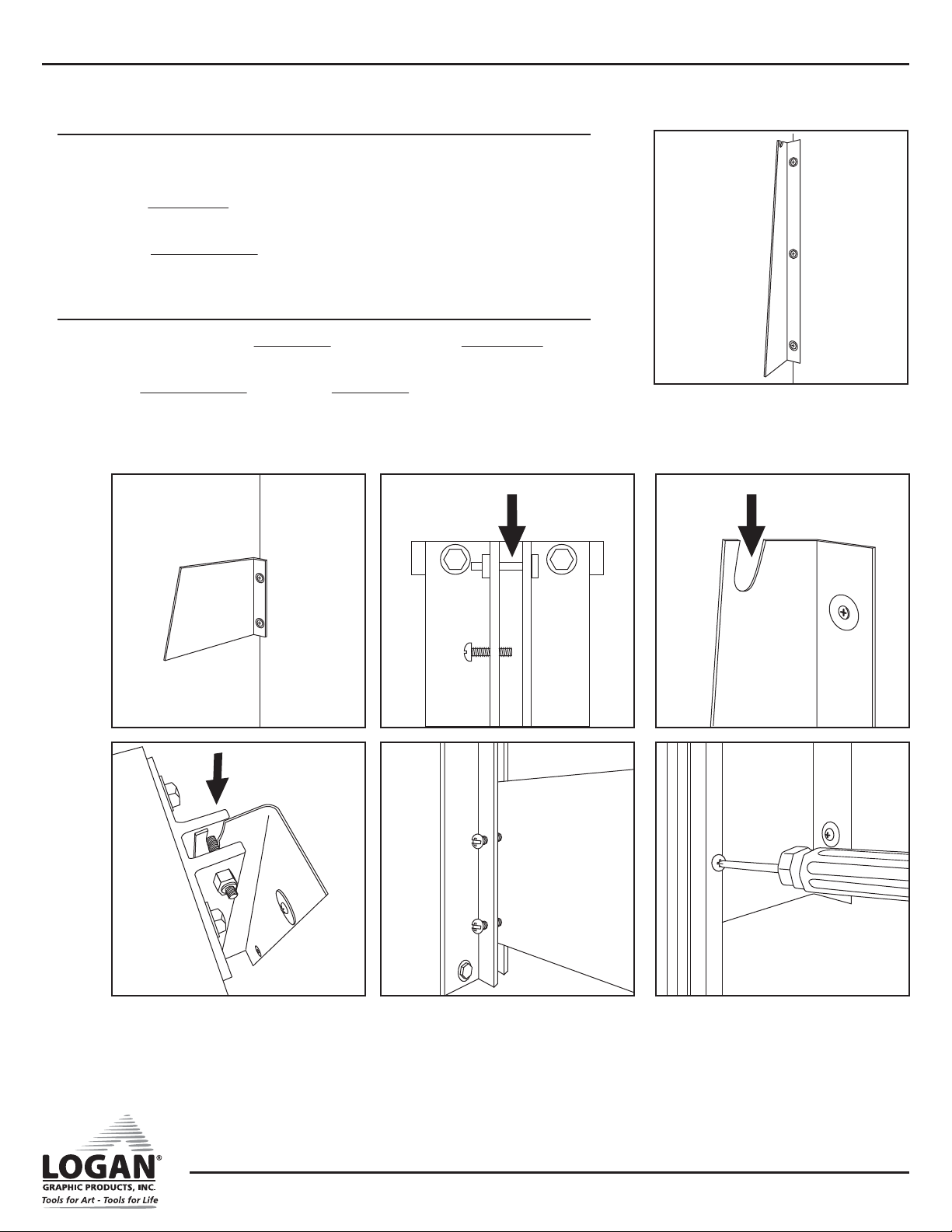
Mount Cutter Bar
1. Carefully fit top pin in Cutting Bar (Fig. 4) into slot in Top Bracket
(Fig. 5) and align bracket edges along bar assembly edge (Fig. 6).
2. Align Bottom Bracket edge along Cutting Bar side (Fig. 7).
3. Tighten five (5) Mount Screws (Fig. 8).
Fig. 2
Fig. 6
Fig. 4Fig. 3 Fig. 5
Fig. 7 Fig. 8
WALL MOUNT
MULTI-MATERIAL CUTTER
G1089 1/22
Instruction Manual Model F700-1
Logan Graphic Products Inc., 1100 Brown Street, Wauconda, IL 60084 847-526-5515 www.logangraphic.com
6
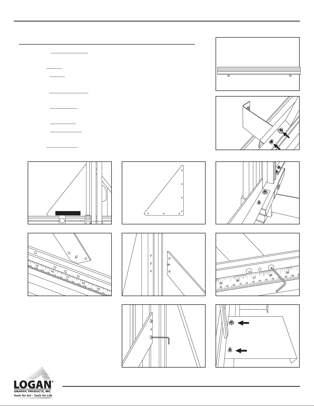
Mounting Cutting Beds
1. Attach Left Cutting Bed (long 48”) (Fig. 9) onto mount bar studs and
secure with two (2) mount nuts (Fig. 10).
2. Align Gusset with left cutting bed and cutting bar assembly (Fig. 11).
3. Attach Gusset with seven (7) flat head screws.
*Note* Attach screws in the order shown (Fig. 12).
4. Attach Right Cutting Bed (shorter 24”) onto mount bar studs and secure
with two (2) mount nuts (Fig. 13).
5. Attach Support Bar by aligning pins in support bar with holes in Right
Cutting Bed and Cutting Bar (Fig. 14 & 15).
6. Secure Support Bar with four (4) screws (Figs. 16A & 16B).
7. Attach Side Brackets onto cutting bed studs with four (4) mount nuts
(Fig. 17).
8. Align Side Brackets to wall, and mark holes with a pencil.
Fig. 9
Fig. 10
Fig. 11 Fig. 12
1
254
7
6
3
Fig. 13
Fig. 14 Fig. 15 Fig. 16A
Fig. 16B Fig. 17
WALL MOUNT
MULTI-MATERIAL CUTTER
G1089 1/22
Instruction Manual Model F700-1
Logan Graphic Products Inc., 1100 Brown Street, Wauconda, IL 60084 847-526-5515 www.logangraphic.com
7
Mounting Cutting Beds
9. Drill marked hole centers.
10. Insert four (4) Wall Mollies into wall holes and hammer flush (Fig. 18).
11. Secure Side Brackets to wall with screws and washers.
Install Material Clamp
1. Holding clamp vertically, slide Material Clamp bracket lock nut into Left
Cutting Bed (Fig. 19).
2. Slide Material Clamp until top mounting screw aligns with top mount
block.
3. Attach top mounting screw (Fig. 20).
4. Adjust clamp to be parallel with guide bars (Fig. 21).
5. Tighten clamp bracket knob.
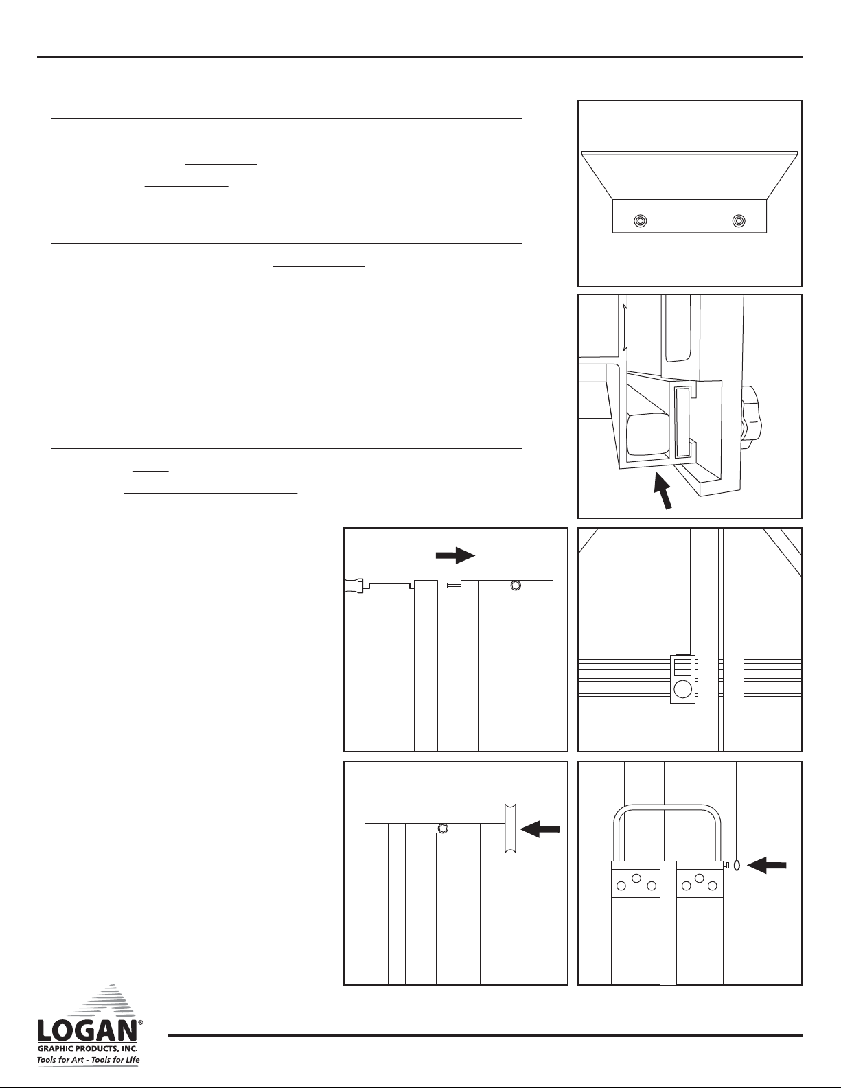
Attach Counter-Balance Weight Bag
1. Attach Pulley to top mount block (Fig. 22).
2. Hook Counter-Balance Weight Bag onto cable post located on right side
of cutting head (Fig. 23).
Fig. 18
Fig. 19
Fig. 21
Fig. 23
Fig. 20
Fig. 22
WALL MOUNT
MULTI-MATERIAL CUTTER
G1089 1/22
Instruction Manual Model F700-1
Logan Graphic Products Inc., 1100 Brown Street, Wauconda, IL 60084 847-526-5515 www.logangraphic.com
8
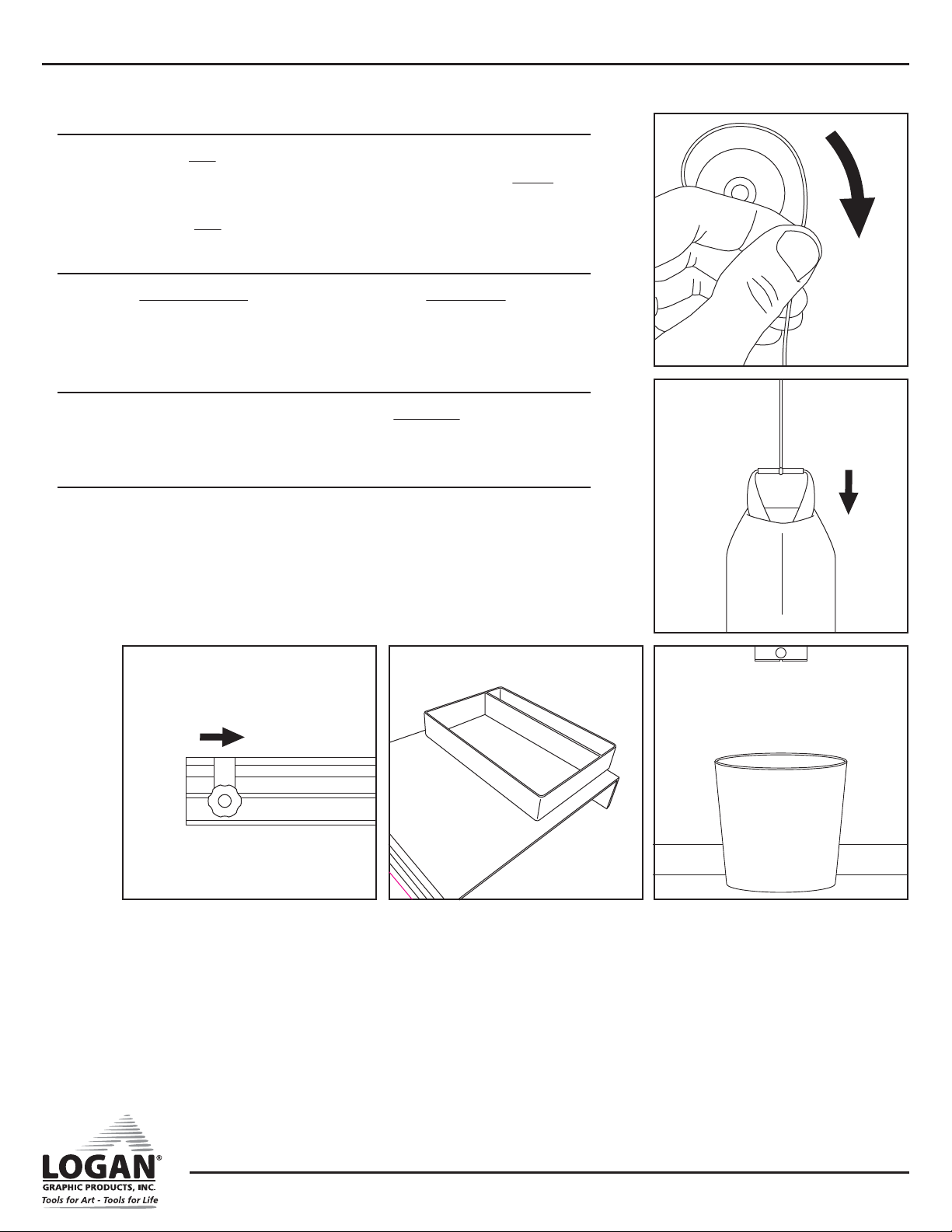
Attach Counter-Balance Weight Bag
3. Holding the Bag in your right hand and keeping tension on the cable
with your left hand, step up on ladder and loop cable over Pulley with
left hand (Fig. 24).
4. Slowly lower Bag until cable is taut (Fig. 25).
Install Production Stop
1. Slide Production Stop lockplate into right or left Cutting Bed and slide to
desired location (Fig. 26).
2. Tighten stop knob to secure.
Install Parts Tray
1. Remove adhesive backing from bottom of Parts Tray.
2. Stick onto right side bracket (Fig. 27).
Use Trash Can
It is recommended that you place a small trash can under bottom of
cutting bar to catch debris (Fig. 28).
Fig. 24
Fig. 25
Fig. 28Fig. 27Fig. 26

WALL MOUNT
MULTI-MATERIAL CUTTER
G1089 1/22
Instruction Manual Model F700-1
Logan Graphic Products Inc., 1100 Brown Street, Wauconda, IL 60084 847-526-5515 www.logangraphic.com
9
Cutting Tool Details
The machine includes three separate interchangeable cutting tools:
• Glass Cutting Tool
• Board Cutting Tool
• Plastic Cutting Tool
Glass Cutting Tool (Red Tip)
• Cuts glass up to 1/4” thick.
• Features a turret design which carries six (6) carbide wheels. Wheels are
numbered 1-6 (Replacement part F57).
• Includes cutting oil for best results.
• Glass wheels “score” glass which is then cracked to separate pieces.
Glass Cutting Tool Wheel Change
1. Loosen turret nut and turret rotation screw (Fig. 29).
2. Rotate turret until next number appears (Fig. 30).
3. Re-tighten both nut and screw.
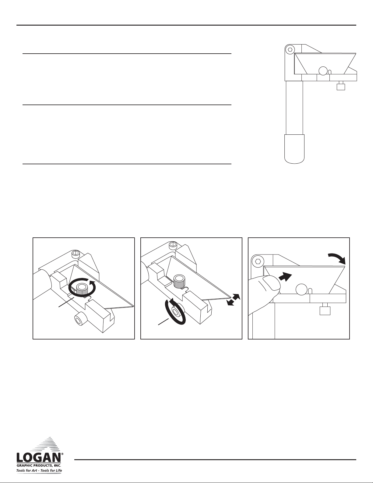
Glass Cutting Tool Turret Change
1. Loosen turret rotation screw one full turn.
2. Remove turret nut.
3. Push turret screw to remove turret (Fig. 31).
4. Replace new turret (Fig. 32).
5. Rotate turret to setting “1” or “I”.
6. Tighten turret rotation screw.
7. Replace and tighten turret nut.
Fig. 32Fig. 31Fig. 30
Fig. 29
Nut
Rotation
Screw
WALL MOUNT
MULTI-MATERIAL CUTTER
G1089 1/22
Instruction Manual Model F700-1
Logan Graphic Products Inc., 1100 Brown Street, Wauconda, IL 60084 847-526-5515 www.logangraphic.com
10
Board Cutting Tool (Yellow Tip)
• Cuts up to 1/2” foam board, mat board, gator board, and cardboard.
• Uses standard utility blade (Replacement Number F58).
• Uses both ends of blade.
• Features blade depth adjustment screw.
Board Cutting Tool Blade Change
1. Remove blade screw (Fig. 33).
2. Rotate or replace blade.
3. Replace blade screw but do not tighten.
4. Push back of blade to reposition blade against depth screw.
5. Tighten blade screw.
Board Cutting Depth Adjustment
1. To adjust, loosen blade screw (Fig. 34).
2. Push back of blade to reposition it against depth screw (Fig. 35).
3. Tighten blade screw.
Fig. 33
Blade Screw
Depth Screw
Fig. 34 Fig. 35
Table of contents
Popular Cutter manuals by other brands

Milwaukee
Milwaukee HEAVY DUTY M12 FCOT Original instructions

SignWarehouse.com
SignWarehouse.com Bobcat BA-60 user manual

Makita
Makita 4112HS instruction manual

GEISMAR STUMEC
GEISMAR STUMEC MTZ 350S manual

Hitachi
Hitachi CM 4SB2 Safety instructions and instruction manual

Dexter Laundry
Dexter Laundry 800ETC1-20030.1 instruction manual


