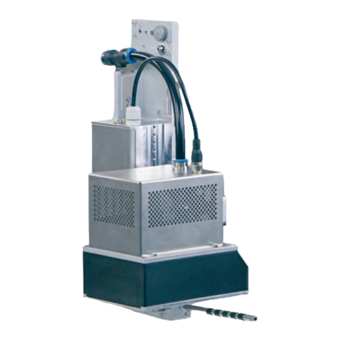
CAB A1000 User manual

Edition 3/04
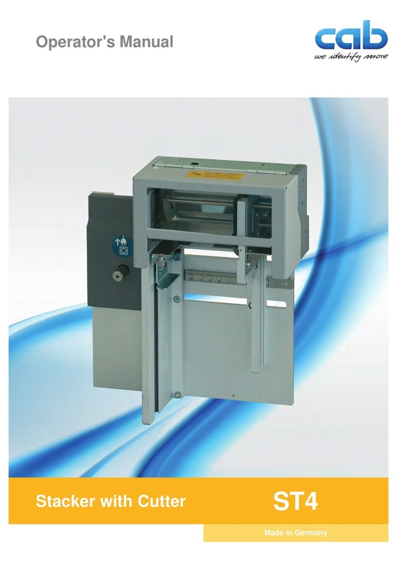
Tamp Applicator A1000
Operator's Manual

cab - Produkttechnik GmbH & Co KG
2
Tamp Applicator A1000
Gesellschaft für
Computer- und Automations-
Bausteine mbH & Co KG
cab-Produkttechnik GmbH & Co KG
Postfach 19 04 D-76007 Karlsruhe
Wilhelm-Schickard-Str. 14 D-76131 Karlsruhe
Telefon +49 (0) 721 / 66 26-0
Telefax +49 (0) 721 / 66 26-249
http://www.cabgmbh.com
copyright by cab / 9008357 / O14 / 1
All rights reserved, including those of the translations.
No part of this manual nor any translation may be reproduced or transmitted in any form or
by any means, for any purpose other than the purchaser's personal use, without the
express written permission of cab Produkttechnik GmbH & Co KG Karlsruhe.
All specifications about delivery, design, performance and weight are given to the best of
our current knowledge and are subject to change without prior notice.

cab - Produkttechnik GmbH & Co KG 3
Tamp Applicator A1000
Table of Contents
Copyright ......................................................................................................................... 2
Table of Contents ............................................................................................................ 3
1. Product Description ............................................................................... 4
Function .................................................................................................................. 4
Important Features ................................................................................................. 5
Technical Data ........................................................................................................ 5
Tamp Pads ............................................................................................................. 6
Blow Pads .............................................................................................................. 7
Roll-on Pads ........................................................................................................... 7
2. Delivery Contents ................................................................................... 8
3. General Safety Instructions ................................................................... 9
4. Mounting ................................................................................................ 10
Mounting the Applicator on the Printer ................................................................ 10
Piercing the Universal Tamp Pad ........................................................................ 11
Preparing the Applicator for Using a Tamp Pad Type A1312 .............................. 12
Mounting the Pad ................................................................................................. 13
Mounting the Stopper for the Operation Mode "Blow On" ................................... 14
Connections ......................................................................................................... 15
5. Printer Configuration ............................................................................ 16
Standard Method for Changing the Printer Configuration ................................... 16
Quick Mode for Adjusting the Delay Times ......................................................... 17
Configuration Parameters for the Applicator ....................................................... 18
6. Adjustments .......................................................................................... 22
6.1.Mechanical Adjustments ...................................................................................... 22
Adjusting the Pad in the Print Direction ............................................................... 22
Adjusting the Level and the Sides of the Cylinder Unit ....................................... 23
Aligning the Pad to the Dispense Edge ............................................................... 24
Opening the Holes on the Blow Tube .................................................................. 24
Tuning the Blow Tube .......................................................................................... 25
Adjusting the Stopper for the Operation Mode "Blow On" ................................... 26
6.2.Pneumatic Adjustments ....................................................................................... 28
Control Valves ...................................................................................................... 28
Pressure Reducing Valves ................................................................................... 30
Throttle Valves at the Cylinder ............................................................................. 31
Throttle Valves at the Manifold ............................................................................ 32
7. Operation ............................................................................................... 33
Standard Operation .............................................................................................. 33
Test Mode Using the Pre-dispense Key without Print Job .................................. 34
Test Mode Using the Pre-dispense Key with Print Job ....................................... 35
Adjusting the Peel Position .................................................................................. 36
Anhang A - PLC Interface
Anhang B - Error Messages
Anhang C - Function of the LED's on the Applicator Electronics
Index
EC Conformity Declaration
cab - Produkttechnik GmbH & Co KG
4
Tamp Applicator A1000
1. Product Description
Function
The Tamp Applicator is an optional device to use with the A3/200P,
A3/300P, A4/300P and A4/600P printers for automatically applying the
printed label onto the product.
The labels are transfered with a pad, which moves between the two
positions, starting position and labelling position, by a compressed-air
driven pneumatic cylinder.
In the starting position, the label is picked up from the printer by the
pad. A sensor at the cylinder signals when the pad is in the starting
position. The label is removed from the carrier ribbon directly at the
dispense edge of the printer. It is sucked on the pad by a vacuum via
drillings at the bottom of the pad. For support, the label is also blown
against the pad with an air current coming from a blow tube. The
correct transfer of the label is controlled by a vacuum sensor.
Next, the pad is moved down into the labelling position, which is
confirmed by another sensor (labelling position sensor). Here, the
label is transferred onto the product.
The label can be applied with three different methods :
1. Tamp on
The label remains in a fixed position. The label is pressed directly
onto the product.
2. Blow on
The pad moves to a pre-adjusted position approximately 10mm
away from the product. The labels is blown onto the product by an
air jet stream. The print and apply cycle performs in a fixed
position or in linear movement of the product.
3. Roll on
The label is dispensed and moved until touching the roller of the
roll on pad. At the labelling position the roller is pressed onto the
product. Then the label is applied and rolled on by the movement
of the product.
While the pad is moving back into the starting position, the vacuum
sensor checks whether the label has been removed from the pad.

cab - Produkttechnik GmbH & Co KG 5
Tamp Applicator A1000
Technical Data
Tamp on Blow on Roll on
Label width in mm 25 - 116 25 - 100 25 - 116
Label height in mm 25 - 150 25 - 100 80 - 150
Cylinder stroke in mm 220/300
Stroke of tamp
below printer in mm 70/150
Compressed air press. 4 to 6 bar
Product surface flat
Important Features
The supporting air and the vacuum as well as the speed of the
cylinder are adjustable. That way the applicator can be adapted to
different label materials and sizes.
The operating pressure for the cylinder is reduced in comparison to
the main pressure of the applicator. So the risk of injury is reduced as
far as possible.
To avoid contamination within the vacuum channels these are cleaned
by air pressure impulse at the end of each application.
For operation in a networked system the 15-pin or 25-pin applicator's
PLC (programmable logic control) interface with potential free inputs
and outputs can be used.
Table 1 Technical Data

cab - Produkttechnik GmbH & Co KG
6
Tamp Applicator A1000
Universal tamp pad A1312
Standard size 116x102
Standard size 116x152
Fig 1b Universal tamp pad A1312 116x152
Tamp Pads
Universal tamp pads (Type A1112 or Type A1312) are available in
different standard sizes. At the universal pads the holes in the pad are
covered by a foil. According to the size of the label the holes may be
pierced by the customer. For that purpose a piercing pin is included in
the delivery contents.
On request, tamp pads customized to the label sized are delivered.
Universal tamp pad A1112
Standard size 70x60
Standard size 90x90
Fig.1a Universal tamp pad A1112 70x60

cab - Produkttechnik GmbH & Co KG 7
Tamp Applicator A1000
Fig. 1d Roll-on pad A1411 bxh
Roll-on Pads
Roll-on pads (Type A1411) are only produced on request customized
to the label size.
Fig. 1c Blow pad A2111 bxh
Blow Pads
Blow pads (Type A2111) are only produced on request customized to
the label size.
The delivery contents of the blow pad include a stopper to adjust the
labelling position.

cab - Produkttechnik GmbH & Co KG
8
Tamp Applicator A1000
1
Fig. 2 Delivery contents
2. Delivery Contents
1- Tamp applicator A1000
2- Pad (as ordered)
3- Cylinder screw (part of the pad)
4- Piercing pin (at universal tamp pads only)
5- Stopper (at blow pads only)
3
24 5

cab - Produkttechnik GmbH & Co KG 9
Tamp Applicator A1000
3. General Safety Instructions
CAUTION !
Make sure that the printer is disconnected from the power supply
and the shutoff valve at the applicator is closed, while installing
the delivered components.
CAUTION !
In operation, moving parts are easily accessible.
This applies especially for the sector, where the pad is moved
between the starting and the labelling position.
During operation do not reach into that sector and keep long hair,
loose clothes, and jewellery distant.
Before any manipulations in those areas, close the shutoff valve.
CAUTION !
Do not try to manipulate or repair parts that are not described in
the manuals of the tamp applicator or the printer.

cab - Produkttechnik GmbH & Co KG
10
Tamp Applicator A1000
4. Mounting
Mounting the Applicator on the Printer
CAUTION !
Make sure that the printer is switched off before mounting the
applicator !
213
1. Insert the pins on the back of the applicator (2) into the holes (3)
of the printer.
Press the applicator against the printer. That way the plug of the
applicator will be connected to the peripheral port (4) of the printer.
2. Secure the applicator (2) with the screw (1).
4
Fig. 4a Mounting the applicator

cab - Produkttechnik GmbH & Co KG 11
Tamp Applicator A1000
3
Piercing the Universal Tamp Pad
On the bottom of the pads there are holes for sucking and holding the
labels by vacuum. When an universal tamp pad is delivered these
holes are covered by a foil and must be opened according to the label
size. For that purpose a piercing pin is included in the delivery
contents.
Fig. 4b Piercing the sliding foil (holes to be opened are bold)
1. Place a label (1) to be operated on the bottom side of the pad (2).
The label must be aligned to the side edge and stand over the rear
edge of the pad by 2 mm.
2. Open all the holes, which are certainly covered by the label. Open
the holes completely by turning the piercing pin (3) inside the
holes.
CAUTION !
Do not open holes, which are located less than 1mm from a label
edge.
12
2 mm
2

cab - Produkttechnik GmbH & Co KG
12
Tamp Applicator A1000
Preparing the Applicator for Using a Tamp Pad Type 1312
Fig. 4c Changing the fitting of the cylinder unit
The cylinder unit (6) can be mounted on the bracket (1) in two
different positions.
When the applicator is delivered, the cylinder unit is mounted on the
bracket using the upper threaded hole (4). That position is suitable for
the most pads.
If you want to use an universal tamp pad type A1312 the fitting of the
cylinder unit must be changed.
1. Loosen the screw (3) with washer (2) and remove the cylinder unit
from the bracket (1).
2. Fix the cylinder unit with screw (3) and washer (2) by using the
lower threaded hole (5).
2
1
3
4

cab - Produkttechnik GmbH & Co KG 13
Tamp Applicator A1000
Fig. 4d Mounting the pad
1. Pull the tube (1) out of the push-in-fitting
2. Insert the pin (6) on the pad (7) into the hole on the bottom side of
the pad holder (4).
3. Fix the pad (7) with the screw (2) at the pad holder (4).
4. Insert the vacuum tube (3) an the blow-air tube into the
appropriate push-in-fittings (5) of the pad.
5. Insert the tube (1) into the appropriate push-in-fitting (5) on the
cylinder.
CAUTION !
To avoid possible collisions of the pad with other parts of the
printer-applicator system, please roughly align the pad in all
directions (see "Mechanical Adjustments") before connecting the
applicator to the compressed air supply !
2
1
4
3
7
5
6
5
Mounting the Pad

cab - Produkttechnik GmbH & Co KG
14
Tamp Applicator A1000
Mounting the Stopper for the Operation Mode "Blow On"
The delivery contents of the blow pads (type A2111) include a
stopper (1). With this stopper the labelling position for the operation
mode "Blow on" can be adjusted.
1. Loosen the screw (2) at the stopper (1).
2. Slide the stopper (1) with the rubber buffer at the bottom side onto
the rods (3).
3. Tighten the screw (2).
For more information on the stopper adjustment see chapter
"Mechanical Adjustments".
Fig. 4e Mounting the Stopper
2
3
12
1

cab - Produkttechnik GmbH & Co KG 15
Tamp Applicator A1000
Connections
1. Prepare the connections to the power supply and to the computer
as described in the manual of the printer.
2. To contact the PLC interface use the 15-pin or 25-pin connector
(for more details see appendix A).
3. Make sure that the shutoff valve (3) is closed (lever at the valve is
turned across the air flow direction).
4. Connect the applicator to the compressed air supply.
The connector (2) for the compressed air supply is located at the
service unit. The connector is suitable for a 1/4" coupling plug (1).
5. The air pressure for operating the applicator has to be adjusted at
the service unit (1).
- Pull knurled knob (4) up.
- Turn knob to tune required operating pressure (4-6 bar).
By turning knob clockwise the pressure rises.
- Push knob down.
6. Open the shutoff valve. (5/ lever is turned in the air flow direction)
7. Switch on the power supply of the printer.
CAUTION !
The pad will immediately moved in the starting position !
Fig. 4f Connections
4231

cab - Produkttechnik GmbH & Co KG
16
Tamp Applicator A1000
5. Printer Configuration
The tamp applicator, with its standard components, can be operated
in different ways. While the original process stays the same, the
operation mode can be chosen within the printer configuration.
The most important setting is the selection between the operation
modes "Stamp on", "Blow on" and "Roll on". Additionally the applicator
has different application modes concerning the order of printing and
applying within one labelling cycle.
Stamp on Blow on Roll on
Print / Apply x x x
Apply / Print
Waiting position up x x x
Apply / Print
Waiting position down x
Standard Method for Changing the Printer Configuration
NOTICE !
Please note the detailed information about the printer
configuration in der Operator's Manual of the printer !
1. Switch to the Offline Menu by pressing the key.
2. Continue to press the key or the key until you reach the
"Setup" menu. Press the key.
3. The parameters are arranged in a tree like structure. Pressing the
key as well as the key will scroll between the secondary
menus. By pressing the key, the selected secondary menu will
be chosen.
Further all operating modes can be adjusted by setting different time
delays.
Table 5a Operation and application modes

cab - Produkttechnik GmbH & Co KG 17
Tamp Applicator A1000
Quick Mode for Adjusting the Delay Times
Beside the standard method for the printer configuration there is a
quick mode to adjust the delay times available.
NOTICE !
The quick mode settings can be made during operation .
The changings affect directly the current print job.
1. Switch to the quick mode by pressing the key and keep it
pressed down for at least 2 seconds.
2. The first delay time appears on the display. Adjust the delay time
by pressing the key or the key.
3. To switch between the different delay times press the key.
4. Press the key to leave the quick setup mode. The selected
delay times are stored in the printer.
4. The parameters for the applicator configuration can be found
under "Setup" -> "Machine parameters" -> "Applicator".
5. Make the parameter setting as necessary.
6. Press the key several times if necessary to return to the
"Online" mode.

cab - Produkttechnik GmbH & Co KG
18
Tamp Applicator A1000
Selection
Stamp on
Blow on
Roll on
Print-Apply
Apply-Print
up
down
0
...
2500
in steps of 10 ms
0
...
5000
in steps of 10 ms
0
...
2500
in steps of 10 ms
0
...
2500
in steps of 10 ms
0
...
2500
in steps of 10 ms
0
...
2500
in steps of 10 ms
+9,9
...
-9,9
in steps of 0.1 mm
Table 5b Applicator parameters
Setup
Machine param.
Parameter Meaning
Applicator
Mode of oper. Setting the operation mode
Default : Stamp on
Mode of appl. Setting the application mode
Default : Print-Apply
Waiting position Waiting position of the pad with
dispensed label
for Blow on + Apply-Print only
Default : up
Blow time Setting the blow time
Parameter only appears in the
operation mode "Blow on"
Default : 0 ms
Roll-on time Setting the roll-on time
Parameter only appears in the
operation mode "Roll on"
Default : 0 ms
Support delay on Setting the switch-on delay for the
supporting air
Default : 0 ms
Support del. off Setting the switch-off delay for the
supporting air
Default : 270 ms
Delay time Setting the start delay
Default : 0 ms
Lock time Setting the locking time
Default : 0 ms
Peel position Shift the position of the dispensed
label relative to the dispensing
edge
Default : 0,0 mm
Configuration Parameter for the Applicator

cab - Produkttechnik GmbH & Co KG 19
Tamp Applicator A1000
Mode of operation
With that parameter the methods for applying the labels on to the
product (Tamp, Blow, Roll on) can be selected.
Mode of application
The tamp applicator can be operated in two different ways referring
the order of printing and labelling within one labelling cycle.
"Print/Apply"
The print of a label is released by an external start signal (via PLC
interface). At the same moment the vacuum on the pad as well as the
supporting air from the blow tube are switched on. When the label is
printed and picked up from the carrier ribbon, the supporting air is
switched off. Then the lift cylinder is driven to move the pad down
towards the labelling position. A sensor signals when the labelling
position is reached.
Following, the vacuum is switched off and the label is placed onto the
product.
After that, the lift cylinder is driven to move the pad back into the
starting position. Thus, the labelling cycle is finished.
"Apply/Print"
Before starting the cyclic operation the printing and picking up of the
first label has to be released separately by a special signal via PLC
interface.
Thus at the start of the cyclic operation when sending the start signal
via PLC, the first label is already on the pad. The following process is
similar to the mode "Print/Apply", but at the end of the cycle the next
label is printed and picked up by the pad. Thus, the labelling cycle is
finished.

cab - Produkttechnik GmbH & Co KG
20
Tamp Applicator A1000
Waiting position
NOTICE !
That parameter is available only when the operation mode "Blow
on" and the application mode ''Apply/Print'' are selected.
Waiting position up
At the cyclic operation the pad with the printed label waits in the
starting position near the dispense plate of the printer for the start
signal.
Waiting position down
At the cyclic operation the pad with the printed label waits in the
labelling position for the start signal. So the cycle starts directly with
blowing the label on to the product.
Blow time
That parameter is available when the operation mode "Blow on" is
selected. The time period can be adjusted, when the blowing air for
the transfer of the label onto the product is switched on.
Roll-on time
That parameter is available when the operation mode "Roll on" is
selected. The time period can be adjusted, when the roll-on pad
remains in the labelling position.
Support delay on
The supporting air from the blow tube is not immediately switched on
when the print of the label is released but delayed. The air is switched
on, when the label has covered a distance.
This delay helps to prevent a turning or swinging at the front of the
label and, consequently, avoids faults when the label is being picked
up from the printer.
Support delay off
Delayed to the process of the label being picked up, the supporting air
is switched off.
In many cases, after being picked up by the pad the label edge may
still stick on the carrier ribbon. This may affect the accuracy of the
label positioning or even cause faults in the labelling. Therefore,
switching off the air blow delayed can be useful to separate the label
from the carrier ribbon and neatly place the label on the surface of the
pad.
Other manuals for A1000
1
Other CAB Printer Accessories manuals