Emulsion information
for the screen printer
A technical information article
by Douglas Grigar
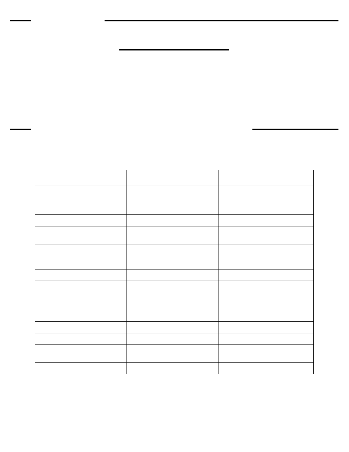
Screen printers have available six types
of photoreactive stencil materials. There
are three direct emulsion choices,
diazo, diazo/photopolymer (dual cure),
and SBQ-photopolymer. There are also
three photo reactive film choices,
indirect film, direct/indirect film, and
photoreactive capillary films.
Diazo emulsions are the least
expensive and the first of the three
emulsion types available on the market.
Diazo emulsions are mid range in
available exposure latitude and can
have good edge definition. Drawbacks
are that many require hardeners for
long runs or water resistance lower
solids content is often needed for
reasonable viscosity.
Diazo Photopolymer emulsions are
hybrids of the diazo and photopolymers
and are also called dual cure. Dual cure
emulsions are the newest available
emulsions. Due to the hybrid nature
they have the largest available feature
and quality range. Dual cure emulsions
will have the largest exposure latitude
and are available in various levels of
water and solvent resistant features.
Dual cure emulsions generally have the
best resolution, definition, and bridging
qualities. Dual cure emulsions are
midrange in price, and higher solids
content versions are available with
reasonable viscosity.
SBQ- Photopolymer emulsions are
very fast in their exposure speeds but
also have the smallest exposure
latitude. They are pre mixed and have
the longest shelf life. Pure
photopolymer emulsions are the most
expensive and are best matched with
high quality single point exposure
systems. Pure photopolymer emulsions
have good resolution, definition, and
bridging qualities. Pure photopolymer
emulsions have the highest solids
content available with reasonable and
often excellent viscosity.
The solids content in an emulsion does
example would be that pure
photopolymer emulsions are available
in very high solids content with low
viscosity. Emulsion viscosity can also
change with temperature. Lower
temperatures cause the emulsions to
thicken. Solids content less than 30%
with low viscosity are often difficult to
coat without a mess. In addition, lower
solids percentage will require multiple
coatings to achieve reasonable mesh
coverage.
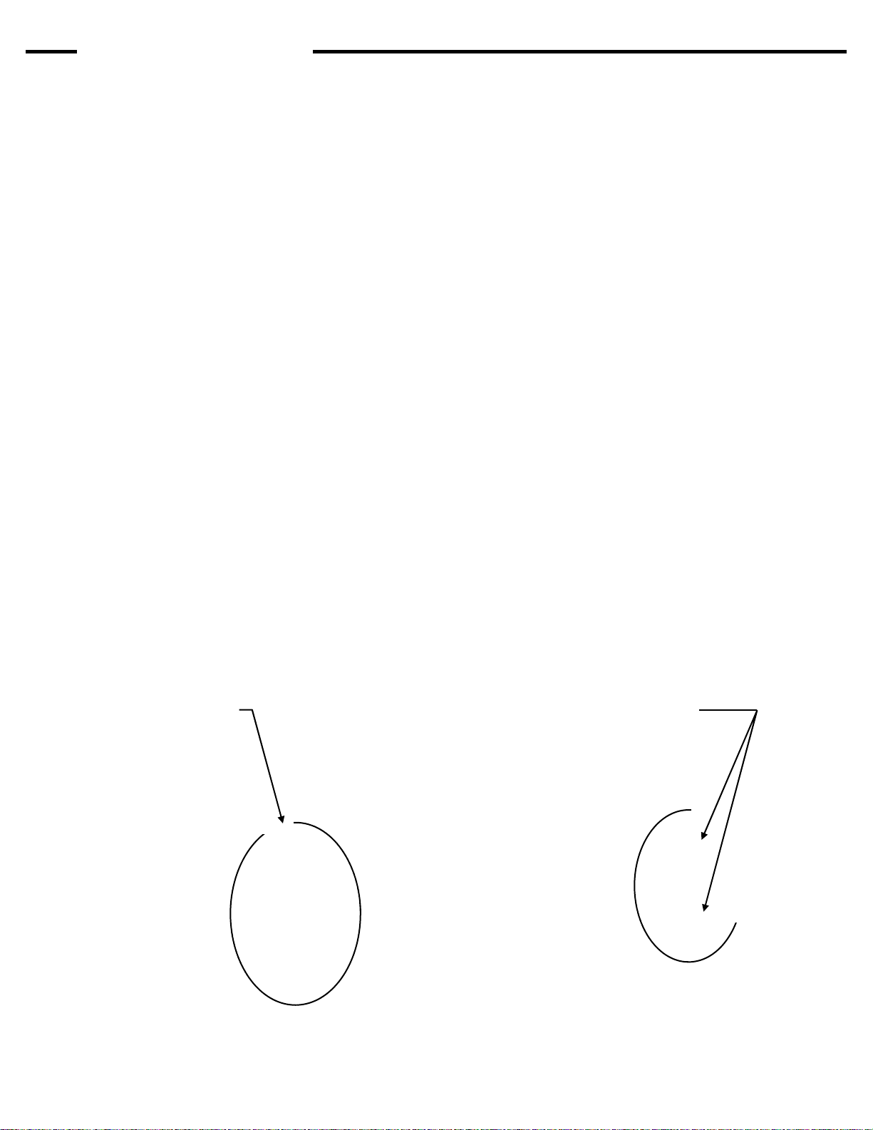
Fig. 1
Emulsion Over Mesh or EOM is a
measurement of the emulsion thickness
on the face or substrate side of the
mesh. EOM is a percentage of the
mesh thickness. (Fig. 1) Too low of an
EOM ratio will prevent a good gasket
seal, prevent good detail resolution,
and increase chances of saw tooth
edges. Manufacturers recommend an
EOM ratio of 10 to 20 percent.
With an emulsion stencil, more is not
better. Too much emulsion on the face
of the screen can cause difficult ink
transfer and details can break down in
a run. Emulsion drip from the mesh
while drying is a definite indication that
the coated emulsion is too thick.
Your emulsion manufacturer can
recommend a coating procedure for
each mesh count using a rounded or
sharp coating edge.
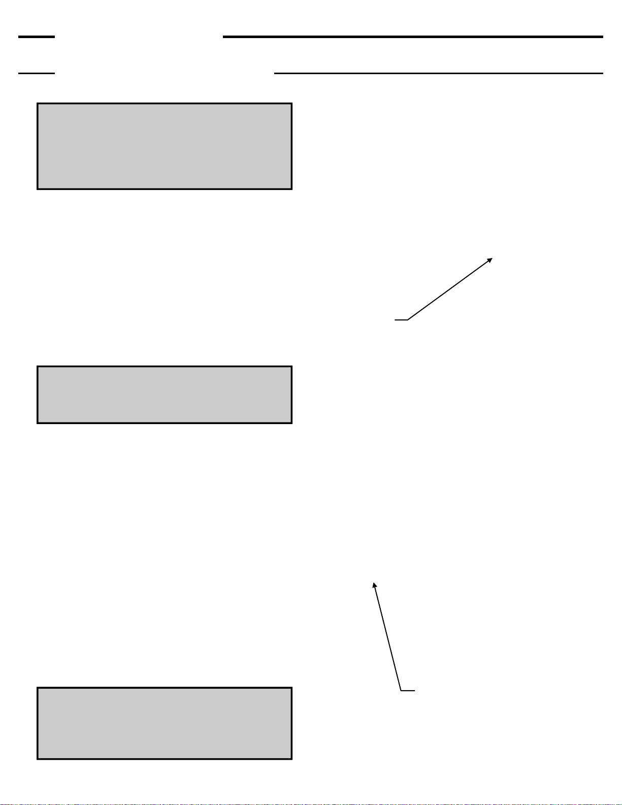
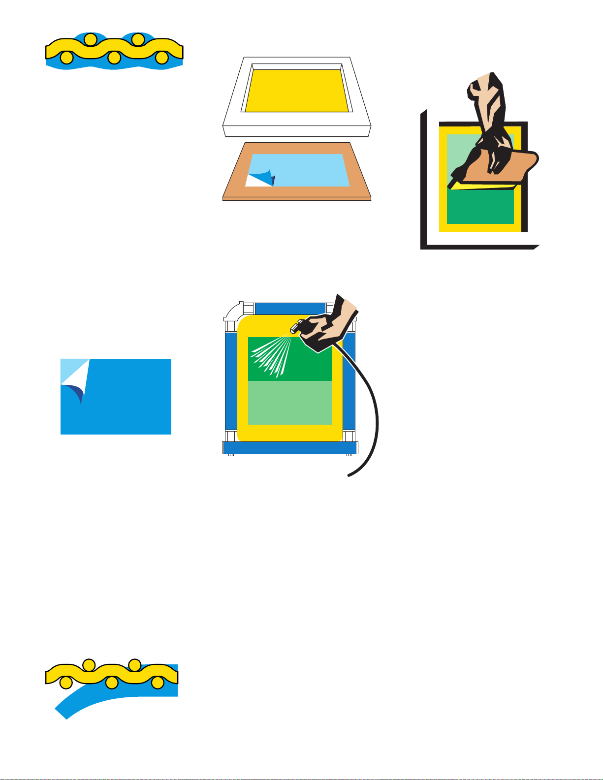
Fig. 2
The step coating procedure (Fig. 2) is
used to coat a screen to find your best
coating technique for that mesh count.
The step coating procedure starts with
a stroke on the face of the mesh. Then
coat the squeegee side once over the
entire screen. Coat again the squeegee
side on only two thirds of the screen,
then coat again one third of the
squeegee side (all wet on wet).
Dry your screen as normal. When dry,
face coat with the sharp edge of the
squeegee two thirds of the screen from
a crossing direction (perpendicular)
then dry face up. When the screen is
dry apply the last coat of emulsion on
the face side covering only one third of
the same direction as the last face coat,
then dry. With the face coatings there
will be nine examples of coating
thicknesses. Pick an exposure time that
fits the median coating technique and
expose the screen with a test positive
that covers all of the coating changes.
Wash out and dry as normal. Now you
can view the emulsion with a loop or
microscope. Inspect the changes in
thickness, then print with this screen
and inspect the printed results. With the
printed results compared to the visual
inspection, the best coating technique
for that mesh count can be determined.
Standardized mesh thread thickness
and weave for each mesh count is
needed for consistent and reliable
results.
The step coating procedure can be
used while eliminating some of the
steps, or replace the face coatings with
all wet on wet coating strokes.
All manufacturers recommend drying
coated screens with the face down
(squeegee side up) in a horizontal
position. A slightly elevated temperature
(not over 110 deg. F.), in a filtered
drying room or cabinet, will dry screens
in record time, often less than half an
hour. A dehumidifier will drop emulsion
drying time further.
Fig 3
Once the screen is dry, direct emulsion
will dry and conform to the profile of the
mesh fabric causing small hills and dips
in the surface. The smoothness of the
dry emulsion can be measured and is
represented by the term Rz value. (Fig.
3) The lower the Rz measurement
number the smoother the surface.