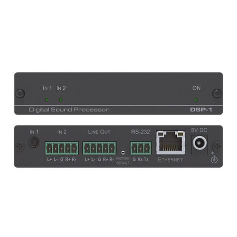
Kramer DSP-1 User manual

Kramer Electronics Ltd.
DSP‑1 –Contents
i
Contents
Introduction 1
Getting Started 1
Overview 2
Typical Applications 3
Defining DSP‑1 Digital Sound Processor 4
Connecting DSP‑1 5
Connecting to DSP‑1 via RS-232 6
Connecting DSP‑1 via the Ethernet Port 6
Using the Web Pages 9
Setting the Audio Output Parameters 11
Setting Device Parameters 12
Managing Web Page Security 14
Viewing the About Page 15
Upgrading the Firmware 16
Technical Specifications 17
DSP‑1 Performance Graphs 18
Default Communication Parameters 20
Protocol 3000 21
Understanding Protocol 3000 22
Kramer Protocol 3000 Syntax 23
Protocol 3000 Commands 24

Kramer Electronics Ltd.
DSP‑1 –Introduction
1
Introduction
Welcome to Kramer Electronics! Since 1981, Kramer Electronics has been providing a world
of unique, creative, and affordable solutions to the vast range of problems that confront the
video, audio, presentation, and broadcasting professional on a daily basis. In recent years, we
have redesigned and upgraded most of our line, making the best even better!
Getting Started
We recommend that you:
•Unpack the equipment carefully and save the original box and packaging materials for
possible future shipment.
•Review the contents of this user manual.
Go to www.kramerav.com/downloads/DSP-1 to check for up-to-date user manuals,
application programs, and to check if firmware upgrades are available (where appropriate).
Achieving the Best Performance
•Use only good quality connection cables (we recommend Kramer high-performance,
high-resolution cables) to avoid interference, deterioration in signal quality due to poor
matching, and elevated noise levels (often associated with low quality cables).
•Do not secure the cables in tight bundles or roll the slack into tight coils.
•Avoid interference from neighboring electrical appliances that may adversely influence
signal quality.
•Position your Kramer DSP‑1away from moisture, excessive sunlight and dust.
This equipment is to be used only inside a building. It may only be connected to other
equipment that is installed inside a building.
Safety Instructions
Caution: There are no operator serviceable parts inside the unit.
Warning: Use only the Kramer Electronics power supply that is provided with the unit.
Warning: Disconnect the power and unplug the unit from the wall before installing.

Kramer Electronics Ltd.
DSP‑1 –Introduction
2
Recycling Kramer Products
The Waste Electrical and Electronic Equipment (WEEE) Directive 2002/96/EC aims to reduce
the amount of WEEE sent for disposal to landfill or incineration by requiring it to be collected
and recycled. To comply with the WEEE Directive, Kramer Electronics has made
arrangements with the European Advanced Recycling Network (EARN) and will cover any
costs of treatment, recycling and recovery of waste Kramer Electronics branded equipment on
arrival at the EARN facility. For details of Kramer’s recycling arrangements in your particular
country go to our recycling pages at www.kramerav.com/support/recycling.
Overview
Congratulations on purchasing your Kramer DSP‑1 Digital Sound Processor.
DSP‑1enables the control of individual volume per input, 3-band parametric EQ, selectable
HPF (High-Pass Filters) at 70Hz and master volume via IP. DSP‑1 is a small form factor and
cost-effective solution suitable for a range of audio applications.
DSP‑1 provides exceptional quality and advanced and user-friendly operation and control:
•2-Input mixing with master volume.
•Hi-Pass Filter –Selectable HPF at 70Hz.
•Professional, Studio Grade Signal Conversion Technology –Includes the latest
generation 32-bit advanced Digital Analog Converter architecture to achieve excellent
dynamic performance and improved tolerance to clock jitter. Maintains the quality of the
original audio signal with selectable sampling rates up to 96kHz.
•3-Band Parametric Equalizer –Frequency, Q-factor & gain control per band.
•Line-Level amplifier for audio gain and attenuation.
•Creates & saves presets.
•Highly cost effective.
Controlling your DSP‑1
Control your DSP‑1via:
•RS-232 serial commands transmitted by a touch screen system, PC, or other serial
controller.
•The Ethernet using built-in user-friendly Web pages.
Kramer Electronics Ltd.
DSP‑1 –Introduction
3
Installing your DSP‑1
Install DSP‑1using one of the following methods:
•Attach the rubber feet and place the unit on a flat surface.
•Fasten a bracket (included) on each side of the unit and attach it to a flat surface. For
more information go to www.kramerav.com/downloads/DSP-1.
•Mount the unit in a rack using the recommended rack adapter (see
www.kramerav.com/product/DSP-1).
Typical Applications
DSP‑1is ideal for the following typical applications:
•Classrooms or educational facilities
•Meeting rooms
•Huddle spaces
•Auditoriums

Kramer Electronics Ltd.
DSP‑1 –Defining DSP‑1 Digital Sound Processor
4
Defining DSP‑1 Digital Sound
Processor
This section defines DSP‑1.
Figure 1: DSP‑1 Digital Sound Processor
#
Feature
Function
IN 1 LED
Lights green when a signal is present on IN 1.
IN 2 LED
Lights green when a signal is present on IN 2.
ON LED
Lights green when the device is powered.
IN 1 3.5mm Mini Jack
Connect to an unbalanced stereo audio source.
IN 2 5-pin Terminal Block Connector
Connect to a balanced stereo audio source.
LINE OUT 5-pin Terminal Block Connector
Connect to a balanced stereo audio acceptor.
FACTORY DEFAULT Recessed Button
Press and hold while powering the device to reset IP
settings to factory default values.
RS-232 (G, Rx, Tx) 3-pin Terminal Block
Connector
Connect to a PC or a serial controller.
ETHERNET RJ-45 Port
Connect to the Ethernet.
5V DC
5V DC connector for powering the unit.

Kramer Electronics Ltd.
DSP‑1 –Connecting DSP‑1
5
Connecting DSP‑1
Always switch off the power to each device before connecting it to your DSP‑1. After
connecting your DSP‑1, connect its power and then switch on the power to each device.
Figure 2: Connecting to the DSP‑1 Rear Panel
To connect DSP‑1 as illustrated in Figure 2:
1. Connect an unbalanced stereo audio source (for example, an MP3) to the IN 1 3.5mm
mini jack .
2. Connect a balanced stereo source (for example, from a PC) to the IN 2 5-pin terminal
block connector .
3. Connect the LINE OUT 5-pin terminal block connector to a balanced stereo audio
acceptor (for example, active speakers).
Connect the left speaker to the “L+” and the “L-” terminal block connectors, and the right
speaker to the “R+” and the “R-” terminal block connectors.
Do not ground the speakers.
4. If required, connect to:
▪A PC or serial controller via the RS-232 3-pin terminal block .
▪A PC via the ETHERNET RJ-45 port .
5. Connect the 5V DC power connector to the power adapter and plug it to the mains
electricity.
We recommend that you use only the power adapter that is supplied with this machine.

Kramer Electronics Ltd.
DSP‑1 –Connecting DSP‑1
6
Connecting to DSP‑1 via RS-232
You can connect to the DSP‑1via an RS-232 connection to the RS-232 port using, for
example, a PC.
Connect the RS-232 terminal block on the rear panel of the DSP‑1to a PC/controller, as
follows (see Figure 3):
•TX pin to Pin 2.
•RX pin to Pin 3.
•GND pin to Pin 5.
Figure 3: RS-232 Connection
Connecting DSP‑1 via the Ethernet Port
You can connect to the DSP‑1via Ethernet using either of the following methods:
•Connecting the Ethernet Port Directly to a PC on page 6.
•Connecting the Ethernet Port via a Network Hub or Switch on page 8.
If you want to connect via a router and your IT system is based on IPv6, speak to your IT
department for specific installation instructions.
Connecting the Ethernet Port Directly to a PC
You can connect the Ethernet port of the DSP‑1directly to the Ethernet port on your PC using
a crossover cable with RJ-45 connectors.
This type of connection is recommended for identifying the DSP‑1 with the factory
configured default IP address.
After connecting the DSP‑1to the Ethernet port, configure your PC as follows:
1. Click Start > Control Panel > Network and Sharing Center.
2. Click Change Adapter Settings.
3. Highlight the network adapter you want to use to connect to the device and click Change
settings of this connection.

Kramer Electronics Ltd.
DSP‑1 –Connecting DSP‑1
7
The Local Area Connection Properties window for the selected network adapter appears
as shown in Figure 4.
Figure 4: Local Area Connection Properties Window
4. Highlight either Internet Protocol Version 6 (TCP/IPv6) or Internet Protocol Version 4
(TCP/IPv4) depending on the requirements of your IT system.
5. Click Properties.
The Internet Protocol Properties window relevant to your IT system appears as shown in
Figure 5 or Figure 6.
Figure 5: Internet Protocol Version 4 Properties Window

Kramer Electronics Ltd.
DSP‑1 –Connecting DSP‑1
8
Figure 6: Internet Protocol Version 6 Properties Window
6. Select Use the following IP Address for static IP addressing and fill in the details as
shown in Figure 7.
For TCP/IPv4 you can use any IP address in the range 192.168.1.1 to 192.168.1.255
(excluding 192.168.1.39) that is provided by your IT department.
Figure 7: Internet Protocol Properties Window
7. Click OK.
8. Click Close.
Connecting the Ethernet Port via a Network Hub or Switch
You can connect the Ethernet port of the DSP‑1to the Ethernet port on a network hub or
using a straight-through cable with RJ-45 connectors.
Control Configuration via the Ethernet Port
To control several units via Ethernet, connect the Master unit (Device 1) via the Ethernet port
to the Ethernet port of your PC. Use your PC provide initial configuration of the settings (see
Connecting DSP‑1 via the Ethernet Port on page 6).

Kramer Electronics Ltd.
DSP‑1 –Using the Web Pages
9
Using the Web Pages
•The web pages enable you to control the DSP‑1via the Ethernet and enable performing
the following operations:
•Setting the Audio Output Parameters on page 11.
•Setting Device Parameters on page 12.
•Managing Web Page Security on page 14.
•Viewing the About Page on page 15.
Before attempting to connect:
•Perform the procedures in Connecting DSP‑1 via the Ethernet Port on page 6.
•Ensure that your browser is supported.
The following operating systems and Web browsers are supported:
OS
Version
Browser
Windows
7
IE
Firefox
Chrome
Safari
10
IE
Edge
Firefox
Chrome
Mac
10.11
Safari
iOS
10.3.2
Safari
Android
N/A
N/A
To browse the DSP‑1 Web pages:
1. Open your Internet browser.
2. Type the IP address of the device in the address bar of your browser. For example, the
default IP address:
Figure 8: Using the Embedded Web Pages –Default IP Address

Kramer Electronics Ltd.
DSP‑1 –Using the Web Pages
10
If the Web pages are password protected, the Authentication window appears:
Figure 9: Using the Embedded Web Pages –Authentication Window
3. Enter the User Name and Password (Admin and Admin by-default) and click OK.
The Output Settings page appears.
Figure 10: Output Settings Page with Navigation List on Left
4. Click the desired Web page or click the arrow to hide the navigation list.

Kramer Electronics Ltd.
DSP‑1 –Using the Web Pages
11
Setting the Audio Output Parameters
The Speaker Output Mixer enables performing the following operations:
•Mixing the Input Signal Levels on page 11.
•Setting Equalization Levels on page 11.
•Setting the Master Volume and Balance on page 11.
Mixing the Input Signal Levels
The indication buttons next to Input 1 and Input 2 appear green when there is an active signal
on that input.
To set the Mixing Level:
1. In the Navigation pane, click Output Settings.
The Speaker Output Mixer page appears (see Figure 10).
2. In the Mix column, use the slides to set the mixing level for each input or enter their
value below the slides.
3. Set the High-Pass Filter ON or OFF to cut off frequencies lower than 70Hz.
To save energy, enable the High-Pass Filter when outputting soft background music or
speech sources.
Setting Equalization Levels
We recommend that you first set the frequencies, then the Q and finally the Bass, Mid and
Treble ranges.
To set EQ levels:
1. In the navigation pane click Output Settings. The Speaker Output Mixer page appears.
2. In the EQ column set the following:
▪Frequency: Bass [60Hz, 80Hz, 100Hz or 200Hz], Mid [500Hz, 1kHz, 1.5kHz or
2.5kHz] and Treble [10kHz, 12.5kHz, 15kHz or 17.5kHz] frequency.
▪Q-Factor: Bass, Mid and Treble [0.1 to 16].
The lower the Q value, the wider the bandwidth.
▪Equalization: Bass, Mid and Treble via the slides or enter their value [dB] below the
slides.
Setting the Master Volume and Balance
In the Master Volume column:
•Use the slide to set the speaker audio level or enter the value [dB] below the slide.
•Click to mute/unmute the output volume.
•Set the left right balance on the speaker output.

Kramer Electronics Ltd.
DSP‑1 –Using the Web Pages
12
Setting Device Parameters
The Device Settings Web page shows the device details, such as name, MAC address and
firmware version. It also allows the following functions:
•Changing the name of the unit by typing the name in the Unit name text box and clicking
Set next to the name.
•Changing the Ethernet Settings on page 12.
•Saving and Loading Settings on page 13.
•Performing a Factory Reset on page 13.
Changing the Ethernet Settings
To change the Ethernet settings, if required:
1. In the Navigation pane, click Device Settings. The Device Settings page appears:
Figure 11: Device Settings Page

Kramer Electronics Ltd.
DSP‑1 –Using the Web Pages
13
2. Set DHCP to ON or OFF.
3. If DHCP is set to OFF, change any of the parameters (IP Address, Netmask and/or
Gateway), if required.
4. Click Set.
•After changing the IP address, reload the web page with the new IP address.
•After changing the Mask address you need to restart the DSP‑1.
•If DHCP is checked, reload the web page with the new IP address.
5. Set the UDP and TCP port numbers and click Set.
Saving and Loading Settings
To save a configuration:
1. In the Navigation pane, click Device Settings.
The Device Settings page appears (see Figure 11).
2. Click Save. The following message appears:
“Configuration file is ready, right-click here to download”.
3. Right-click the link (right-click here) and click Save link as.
The configuration is downloaded to your PC.
To load a configuration:
1. In the Navigation pane, click Device Settings.
The Device Settings page appears (see Figure 11).
2. Click Load and browse for the configuration file.
3. Click Open.
The configuration loads (this process may take a few minutes to complete).
A message indicating that the configuration uploaded successfully appears.
Performing a Factory Reset
To reset the device to its factory default values:
1. In the Navigation pane, click Device Settings.
The Device Settings page appears (see Figure 11).
2. Click Factory reset.
A confirmation warning message appears.
3. Click OK to start factory reset and follow the instructions on-screen.

Kramer Electronics Ltd.
DSP‑1 –Using the Web Pages
14
Managing Web Page Security
Use the Authentication page to set Web access permission.
To access Web pages without using the password:
1. In the Navigation pane, click Security.
The Authentication page appears (see Figure 12).
Figure 12: Authentication Page
2. Set Activate Security to Disabled.
A message prompting for your password appears.
3. Type the current password (Admin by default) and click OK.
A message indicating that the password was changed successfully appears.
4. Click OK.
The Web page reloads and the web pages are unlocked .

Kramer Electronics Ltd.
DSP‑1 –Using the Web Pages
15
To access Web pages using the password:
1. In the Navigation pane, click Security.
The Authentication page appears (see Figure 12).
2. Set Activate Security to Enabled for Web page password protection.
A confirmation warning message appears:
3. Click OK.
The connection is interrupted, and authentication is required to access web pages.
Figure 13: Password Settings Page –Security Log In
4. Type the User Name (Admin, by default) and Password (Admin, by default).
5. Click Log In.
6. Select Security from the Navigation pane.
The Authentication page appears (see Figure 12).
7. Type the new authentication password twice in both New and Retype New text boxes.
8. Click Change.
A confirmation warning message appears.
9. Click OK. The following message appears.
A message indicating that the password was changed successfully appears.
10.Click OK.
The web pages are locked .
Viewing the About Page
The About page lets you view the web page version and Kramer Electronics Ltd details.

Kramer Electronics Ltd.
DSP‑1 –Upgrading the Firmware
16
Upgrading the Firmware
You can upgrade the DSP‑1via the Ethernet or RS-232 using Kramer K-UPLOAD tool.
The latest firmware version and the latest version of K-UPLOAD and installation
instructions can be downloaded from the Kramer Web site at
www.kramerav.com/downloads/DSP-1.

Kramer Electronics Ltd.
DSP‑1 –Technical Specifications
17
Technical Specifications
Inputs
Balanced Stereo Audio
On a 5-pin terminal block connector
Unbalanced Stereo
Audio
On a 3.5mm mini jack
Output
Balanced Stereo Audio
On a 5-pin terminal block connector
Ports
RS-232
On a 3-pin terminal block connector
Ethernet
On an RJ-45 female connector
Audio
Frequency Response
20Hz to 20kHz, ±0.3dB
Signal to Noise Ratio
>110dB, 20Hz to 20kHz, at unity gain
(unweighted)
THD+N
<0.01%, 20Hz to 20kHz, at unity gain
Crosstalk
< -85dB, 20Hz to 20kHz
Input Impedance
10KΩ
Output Impedance
150Ω
Supported
Web Browsers
Windows 7
Internet Explorer, Firefox, Chrome, Safari
Windows 10
Internet Explorer, Edge, Firefox, Chrome
MAC 10.11
Safari
iOS 10.3.2
Safari
Android
N/A
Power
Consumption
5V DC, 350mA
Source
5V DC, 4A
Environmental
Conditions
Operating Temperature
0° to +40°C (32° to 104°F)
Storage Temperature
-40° to +70°C (-40° to 158°F)
Humidity
10% to 90%, RHL non-condensing
Regulatory
Compliance
Safety
CE
Environmental
RoHs, WEEE
Enclosure
Size
Tool
Type
Aluminum
Cooling
Convection ventilation
General
Net Dimensions
(W, D, H)
12cm x 7.2cm x 2.4cm
(4.7" x 2.8" x 0.9")
Shipping Dimensions
(W, D, H)
15.7cm x 12cm x 8.7cm
(6.2" x 4.7" x 3.4")
Net Weight
0.2kg (0.4lbs)
Shipping Weight
0.6kg (1.3lbs) approx.
Accessories
Included
Power adapter and cord
Optional
For optimum range and performance use
the recommended Kramer cables available
at www.kramerav.com/product/DSP-1
Specifications are subject to change without notice at www.kramerav.com

Kramer Electronics Ltd.
DSP‑1 –Technical Specifications
18
DSP‑1 Performance Graphs
The following graphs present the DSP‑1 performance.
DSP‑1 Frequency Response
Figure 14: Frequency Response
DSP‑1 Signal to Noise Ratio
Figure 15: Signal to Noise Ratio
Other manuals for DSP-1
2
Table of contents
Other Kramer Recording Equipment manuals

Kramer
Kramer DSP-1 User manual

Kramer
Kramer PT-102VN User manual

Kramer
Kramer 401DXL User manual

Kramer
Kramer KT-2010 User manual

Kramer
Kramer DSP-62-AEC User manual

Kramer
Kramer DigiTOOLS 6809HD User manual

Kramer
Kramer VS-21TS User manual

Kramer
Kramer SP-4D User manual

Kramer
Kramer RC-3TBU User manual

Kramer
Kramer FC-404NET User manual

Kramer
Kramer DigiTOOLS 6808 User manual

Kramer
Kramer VS-12DPIR User manual

Kramer
Kramer DSP-1 User manual

Kramer
Kramer PS-1FW User manual

Kramer
Kramer VA-256 User manual

Kramer
Kramer TP-576 User manual

Kramer
Kramer VA-10 User manual

Kramer
Kramer WAS-3 User manual

Kramer
Kramer VS-12DPIR User manual

Kramer
Kramer VA-15XL User manual