GRAPHTEC GL840 User manual


Contents
Thank you for choose the midi LOGGER GL840.
This Quick Start Guide describes the basic operations.
Please refer to the manual (PDF) in the CD-ROM for more information.
Nomenclature ……………………………………………………… 2
Connection Procedures ……………………………………………3
Precautions to Observe When Performing Measurement
………5
Descriptions of the Control Panel Keys ………………………… 7
Descriptions of the Menu Screens …………………………… 10
Measurement Procedure…………………………………………11
1. Preparations :
How to Make the Preparations Required for Data Capture
…………………
11
2. Setup : How to Make the Settings ……………………………………………12
3.
Data Capture : How to Capture Data
…………………………………………15
4.
Data Replay : How to Replay Captured Data
………………………………16
Convenient Functions …………………………………………… 17
Trigger Functions to Control Data Capture Start/Stop Operations
………… 17
Span, Position and Trace Functions to Adjust the Waveform Display
……… 19
Specifications
………………………………………………………20
Standard Specifications
…………………………………………………………20
External Input/Output Functions
…………………………………………………20
Common specification of the terminal in the input section
………………… 21
Specification of input section
(GL840-M with standard terminal)
…………………… 21
Specification of input section
(GL840-WV Withstand High Voltage high-precision terminal)
… 22
Installation Guide
…………………………………………………22
After unpacking, check the GL840's Exterior to make sure that
there are crack or other damage before use.
• Quick Start Guide : 1 • SD memory card: 1 • Ferrite core: 1
• CD-ROM : 1 • AC cable/AC adapter : 1
Checking the Outer Casing
Checking the Accessories
1

2
Nomenclature
Two battery pack can be installed
(Battery pack is the option B-569)
Battery cover
Monitor Power switchControl panel keys
Label
Bottom Panel
Front Panel
Power jack for humidity sensor
Humidity sensor
(Option: when using the B-530)
GND terminal
Operation status LED
• POWER
• START
• CHARGE
AC adapter jack
SD CARD2
SD CARD1
External input/output terminals
• LOGIC/PULSE
• EXT TRIG/SAMPLE
• ALARM
Input/out put cable for GL
(Cable is the option B-513)
(Option: when using
• Temperature and humidity sensor
• 4ch voltage/temperature terminal
• 3-axis acceleration/temperature sensor
• 4ch thermistor terminal
• Adapter for AC current sensor
• CO2 sensor
• Illumination/ultraviolet sensor
• Branch adapter for GS.)
Wireless unit
(Option: when using the B-568)
Tilt foot
• Standard terminal (B-564)
• Withstand High Voltage high-precision terminal
(B-565)
Analog signal input terminals
Top Panel
LAN interface terminal USB interface terminal
GS sensor and terminal/
adapter connection terminal
Wireless LAN
connection terminal
Connection Procedures
A
B
bb
Voltage input
CH1...................................................CH20. Thermocouple input
Resistance temperature detector input Current input
+
-
b
+
-
Compensation wire is
used if it is required.
+
-
DC voltage input
+
-
+
-
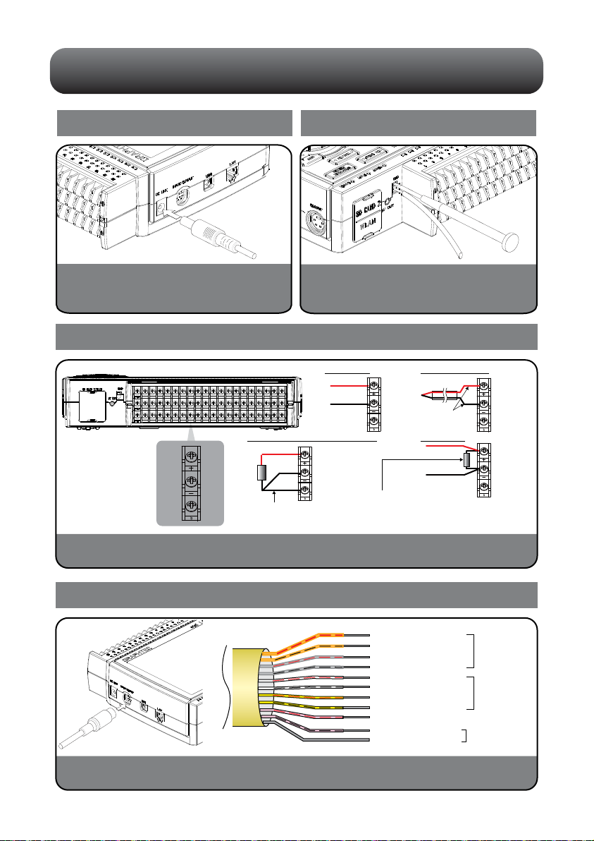
Orange with red dotted line : 1
Orange with black dotted line : 2
Grey with red dotted line : 3
Grey with black dotted line : 4
White with red dotted line : 1
White with black dotted line : 2
Yellow with red dotted line : 3
Yellow with black dotted line : 4
Pink with red dotted line : Trigger input/
external sampling input
Shielded GND
Logic/pulse
input
Alarm output
< Signal assignment >
Pink with black dotted line
Connecting the AC Adapter
Connect the DC output of the AC adapter to the
connector indicated as "DC LINE" on the GL840.
Connecting the Grounding Cable
Use a flathead screwdriver to push the button above
the GND terminal while connecting the grounding
cable to the GL840. Connect the other end of the
cable to ground.
Lead wire resistance should be
10 Ω or less per wire, three
wires need to be same length.
Shunt resister
Ex: The current is converted to the voltage in the
shunt register.
For 4 to 20mA current input, installing 250 ohms
(0.1%) resister for converting 1 to 5V.
Note: 250 Ω shunt register is the option B-551.
Making Connections to the Analog Input Terminals
CAUTION: Connect wires to the specified channel, the channel number is shown on top of the terminal block.
Making Connections to the External Input/Output Terminals
* The B-513 input/output cable for GL (sold separately) is required for connecting input/output signals.
(For logic/pulse input, alarm output, trigger input, external sampling pulse input)
3
A-type connector B-type connector
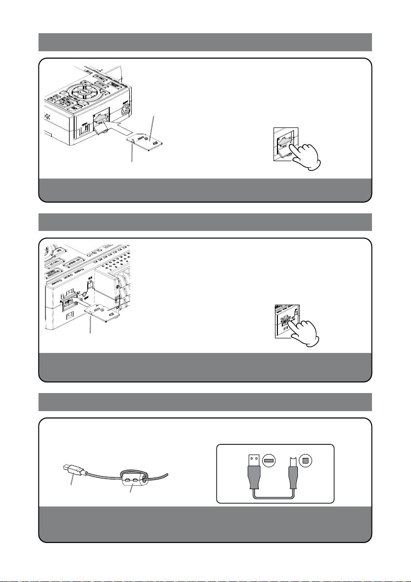
Mounting of the SD CARD 1
CAUTION: When removing the SD memory card, make sure that the SD card display on the display is green
and then remove it.
Mounting of the SD CARD 2
CAUTION: The SD memory card is unlocked by pushing gently the SD memory card. Then, remove the SD
memory card.
When the optional wireless LAN unit is installed, the SD memory card cannot be mounted.
Connection of the USB cable
This midi LOGGER complies with the EMC Directive in the state when the supplied ferrite core is attached to the
USB cable.
When connecting with the USB cable, the USB driver must be installed to the PC. For information about how to
install, refer to the "USB Driver Installation Manual" in the supplied CD-ROM.
* Make sure that the SD memory card is not locked.
< How to mount >
* Make sure that the SD memory card is not locked.
(1) Open the protective cover
of SD CARD 1.
(2) Push the SD memory card
until it clicks and is
locked.
< How to remove >
(1) The SD memory card is
unlocked by pushing
gently the SD memory
card. Then, remove the
SD memory card.
< How to mount >
(1) Open the protective cover
of SD CARD 2.
(2) Push the SD memory card
until it clicks and is
locked.
When connecting to the PC with
the USB cable, attach the supplied
ferrite core to the USB cable as
shown in the following figure.
Using the cable with A-type and B-type connectors,
connect between the midi LOGGER and PC.
< How to remove >
(1) The SD memory card is
unlocked by pushing
gently the SD memory
card. Then, remove the
SD memory card.
4
USB cable
Ferrite core (Supplied)
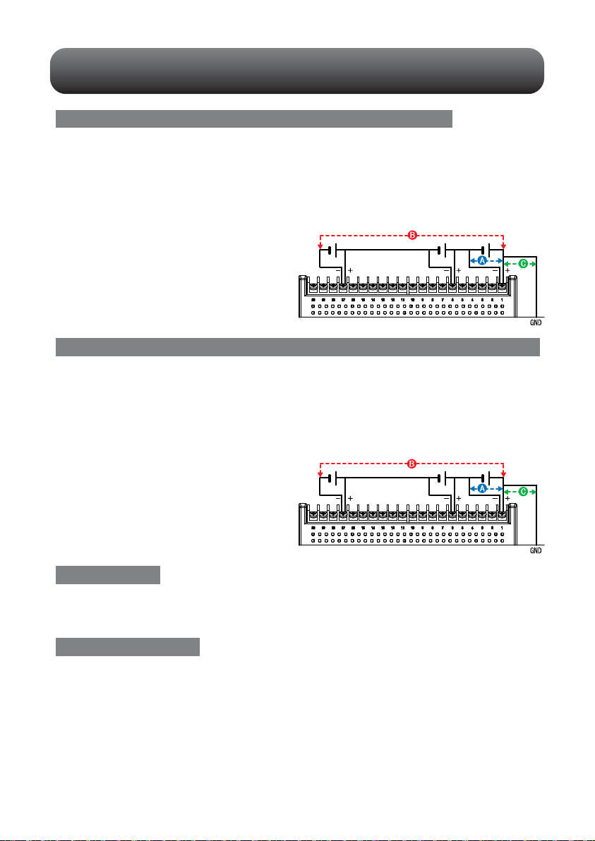
Precautions to Observe When Performing Measurement
Maximum input voltage of standard terminal (B-564)
If a voltage exceeding the specified value is input, the semiconductor relay in the
input section will be damaged. Never input a voltage exceeding the specified value
even for a moment.
< Between +/– terminals(A) >
• Maximum input voltage: 60Vp-p (Range of 20mV to 2V)
110Vp-p (Range of 5V to 100V)
< Between input terminal/input terminal (B) >
• Maximum input voltage: 60Vp-p
• Withstand voltage: 350 Vp-p at 1 minute
< Between input terminal/GND (C) >
• Maximum input voltage: 60Vp-p
• Withstand voltage: 350 Vp-p at 1 minute
Maximum input voltage of Withstand High Voltage high-precision terminal (B-565)
If a voltage exceeding the specified value is input, the semiconductor relay in the
input section will be damaged. Never input a voltage exceeding the specified value
even for a moment.
Warming-up
GL840 requests to have approximately 30 minutes warm-up in order to have the
specified performance.
Unused channels
The analog input section has high impedance.
If it is open, measured value may vary due to noise.
In such a case, set to "Off" unused channels in the AMP setting menu or short the +
and – terminals.
< Between +/– terminals(A) >
• Maximum input voltage: 60Vp-p (Range of 20mV to 2V)
110Vp-p (Range of 5V to 100V)
< Between input terminal/input terminal (B) >
• Maximum input voltage: 600Vp-p
• Withstand voltage: 600Vp-p
< Between input terminal/GND (C) >
• Maximum input voltage: 300Vp-p
• Withstand voltage: 2300 VACrms at 1 minute
5

6
Noise countermeasures
If measured values fluctuate due to extraneous noise, conduct the following
countermeasures.(Results may differ according to noise type.)
Ex 1 : Connect the GL840's GND to ground.
Ex 2 : Connect GL840's GND to measurement object's GND.
Ex 3 : Operate GL840 with batteries (Option: B-568).
Ex 4 : In the AMP settings menu, set filter to any setting other than "OFF".
Ex 5: Set the sampling interval which enables GL840’s digital filter
(see table below).
*1 Number of Measuring Channels is the number of channels in which input settings are
NOT set to “OFF” .
*2 Temperature cannot be measured when the sampling interval is set to 10 ms/20 ms or
50 ms.
In the "OTHER" menu, the commercial power frequency to be used must be
set.
Set the AC power frequency to be used.
Device to be
measured
Z3
GL840
Z1 Z2
Thermocouple Input terminals Vin
R1
R2
Select items
50 Hz
60 Hz
Area where the power frequency is 50 Hz
Area where the power frequency is 60 Hz
Description
Number of Measuring
Channels *1
1 chahnnel or less
5 chahnnels or less
2 chahnnels or less
10 chahnnels or less
11 to 20 chahnnels
21 to 50 chahnnels
51 to 100 chahnnels
101 to 200 chahnnels
10 msec or slower *2
50 msec or slower *2
20 msec or slower *2
100 msec or slower
200 msec or slower
500 msec or slower
1 sec or slower
2 sec or slower
50 msec or slower
250 msec or slower
125 msec or slower
500 msec or slower
1 sec or slower
2 sec or slower
5 sec or slower
10 sec or slower
Allowed Sampling
Interval
Sampling Interval which
enables Digital Filter

Descriptions of the Control Panel Keys
(2) SPAN/TRACE/POSITION
(1) CH GROUP
(3) TIME/DIV
(4) MENU
(5) QUIT
(6) DIRECTION KEYS
(7) ENTER
(8) FAST FORWARD (KEY LOCK)
(9) START/STOP (USB DRIVE MODE)
(10) REVIEW
(12) CURSOR (ALARM CLEAR)
(13) FILE
(14) NAVI
(11) DISPLAY
+ + ENTER
Password setting
Press this key to switch to the next group consisting of 10 channels.
Press the key to switch to the previous group.
Press the key to switch to the following group.
*
When installing the GS sensor and terminal/module (sold separately), the following group display is viewed.
1.CH GROUP
Press the [TIME/DIV] key to change the time axis display range on the waveform
screen.
3.TIME/DIV
This key enables SPAN, POSITION, and TRACE settings to be made
independently fo reach channel. Each time this key is pressed, the display mode
changes in the sequence shown below. Use the and keys to select the
channel, and the and keys to change the setting values.
2.SPAN/TRACE/POSITION
MONITOR
SPAN
POSITION
TRACE
Points to Remember
Displays digital values (default).
Used to change span settings (change the waveform amplitude).
Used to change position settings (adjust the upper and lower values
of the waveform).
Used to change trace settings (set the waveform display to On or Off).
* If the QUIT key is pressed when the GL840 is in the SPAN, POSITION, or
TRACE mode, the display returns to MONITOR mode.
7

8
Press the [MENU] key to open a setup menu. Each time this key is pressed, the
setup screen tabs change in the sequence shown below.
4.MENU
Press the [QUIT] key to cancel the settings and return them to their default status.
If the device is in the Remote (Key Lock) status that the device is operated by the
computer via the interface, press this key to return the device to the normal
operating status (Local).
5.QUIT (LOCAL)
These keys are used to select menu setup items, to make span settings in the digital
display area, to move the cursors during a data replay operation, and so forth.
6.Keys (DIRECTION KEYS)
Press the [ENTER] key to enter the settings made in the setup menus, and to
confirm your settings.
7.ENTER
These keys are used when you want to move the cursor quickly during replay or
change the display mode on the “Digital + Operation” screen. Hold down both keys
simultaneously for at least two seconds to enable key lock status.
To cancel key lock status, press them again for at least two seconds.
The key lock status can be confirmed by the status of the key lock lamp on the
monitor.
* Pressing these keys simultaneously with the key + ENTER + key enables password protection
for the key lock operation.
8.Keys (KEY LOCK)
Points to Remember
•AMP Settings
Used to set the input, range, filter and other settings.
•Data Capture Settings
Used to set settings such as the sampling interval, data capture
destination, and calculations during data capture.
•Trigger Settings
Used to specify data capture start and stop conditions, and alarm
conditions.
•Interface Settings
Used to set the device ID in the USB and the IP address for the
LAN.
•Wireless LAN setting
(displayed when the option is installed)
Used to set the connection to the wireless LAN after the wireless
unit is installed.
•Other Settings
Used to set the screen brightness, background color, and language,
etc.
AMP
DATA
TRIG
I/F
WLAN
OTHER

Press the [START/STOP] key to perform start and stop of a data capture while the
GL840 is in the Free Running status.
If this key is held down while the power to the GL840 is turned on, the GL840 is
switched the SD memory card to the Drive Mode.
* For more information about the Drive Mode of the SD memory card, refer to the User's Manual in
the supplied CD.
9.START/STOP (USB DRIVE MODE)
Press the [REVIEW] key to replay captured data. If the GL840 is in the Free
Running status, data files that have already been captured are replayed. If the
GL840 is still capturing data, the data is replayed in a 2-screen format.
* A data replay operation will not be performed if data has not been captured.
10.REVIEW
Press the [DISPLAY] key
11.DISPLAY
Press the [CURSOR] key to switch between the A and B cursors during a data
replay operation.
If the Alarm setting has been specified as "Alarm Hold", press this key to clear the
alarm.
The alarm settings are made in the "TRIG" menu.
12.CURSOR (ALARM CLEAR)
Press the [FILE] key to operate saving the replaying data to the SD memory card,
copying the screen, and saving/reading the settings as well as replacing the SD
memory card during data capture.
13.FILE
When this key is pressed during free-running, you can perform the setting easily on
the menus of the easy capture setting, easy trigger setting, and wireless LAN
connection setting (available only when the wireless unit is inserted.).
14.NAVI
Points to Remember
•Waveform + Digital
This is the default screen when the GL840 is turned on,
and both waveforms and digital values are displayed.The
screen settings can also be changed by using the
[SPAN/TRACE/POSITION] key.
•Full-screen Waveform
Displays waveform only in the full-screen.
* For more information, refer to the User's Manual in the
supplied CD.
•Digital + Calc
Displays large-size digital values and two types of
calculation processing results. The calculation settings are
made in the "DATA" menu.
Use the key or key to switch digital display
modes.
Waveform + Digital
Full-screen Waveform
Digital + Calc
9
10
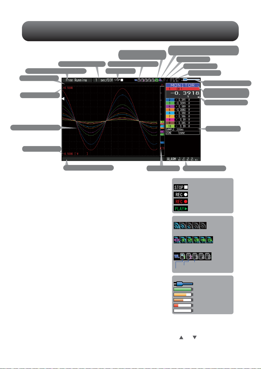
Descriptions of the Menu Screens
1. Status message display area
2. Time/DIV display area
3. Status mark
7. Remote lamp
8. Key lock lamp
9. Clock display
10. AC/Battery status indicator
11. Waveform operation
display area
12. Digital display area
13. Quick settings
14. Alarm display area15. Pen display
16. File name display area
17. Scale lower limit
19. Scale upper limit
20. Data capture bar
18. Waveform display area
Status message
display area
Time/DIV display area
Status mark
Wireless sensor display
Device access display
(SD memory card 1)
Device access display
(SD memory card 2 /
wireless LAN display)
Remote lamp
Key lock lamp
Clock display
AC/Battery status
indicator
Waveform operation
display area
Digital display area
1.
2.
3.
4.
5.
6.
7.
8.
9.
10.
11.
12.
Free Running status
Status mark
Capturing recording status
Data replay status
Trigger waiting status
Capture end status
AC/Battery Indicator
Battery power: 100 - 91%
When the AC power
supply is being used
Battery power: 90 - 61%
Battery power: 60 - 31%
Battery power: 30 -o 11%
Battery power: 1% or less
: Displays the operating status.
: Displays the current time scale.
: Displays the status mark.
: Displayed when connecting the
GL100-WL (GS sensor and terminal /
module connection) to the wireless LAN.
: Displayed in red when accessing the SD
memory card 1.
When the SD memory card 1 is inserted, it
is displayed in green.
: Displayed in red when accessing the SD
memory card 2.
When the SD memory card 2 is inserted, it
is displayed in green.
(When connecting to the wireless LAN as
a child unit, the radio field intensity of the
base unit is displayed. When setting to the
base unit, the number of child units
(wireless sensor) which are connecting to
the GL840 is displayed.)
: Displays the remote status. (Yellow =
Remote status, white = Local status)
: Displays the key lock status. (Yellow =
keys locked, white = not locked)
: Displays the current date and time.
: Displays the following icons to indicate the
operating status of the AC power and the
battery. (see right figure)
Note: Use this indicator as a guideline
because remaining battery power is an estimate.
This indicator does not guarantee the operating time with battery.
: Displays the mode selected by the [SPAN/TRACE/POSITION] key.
: Displays the input values for each channel. The and keys can be used
to select the active channel (enlarged display). Moreover, the selected
active channel is displayed at the very top of the waveform display.
Status icon
Wireless sensor unregistration display
Wireless sensor registration / unrecognization display
Wireless sensor registration / recognization display
Radio field intensity display of base unit
(5 stages from Strong to Weak)
When setting to base unit: The number of
child units which are connecting to the
GL840 is displayed.
4. Wireless sensor display
5. Device access display
(SD memory card 1)
6. Device access display
(SD memory card 2 / wireless LAN display)
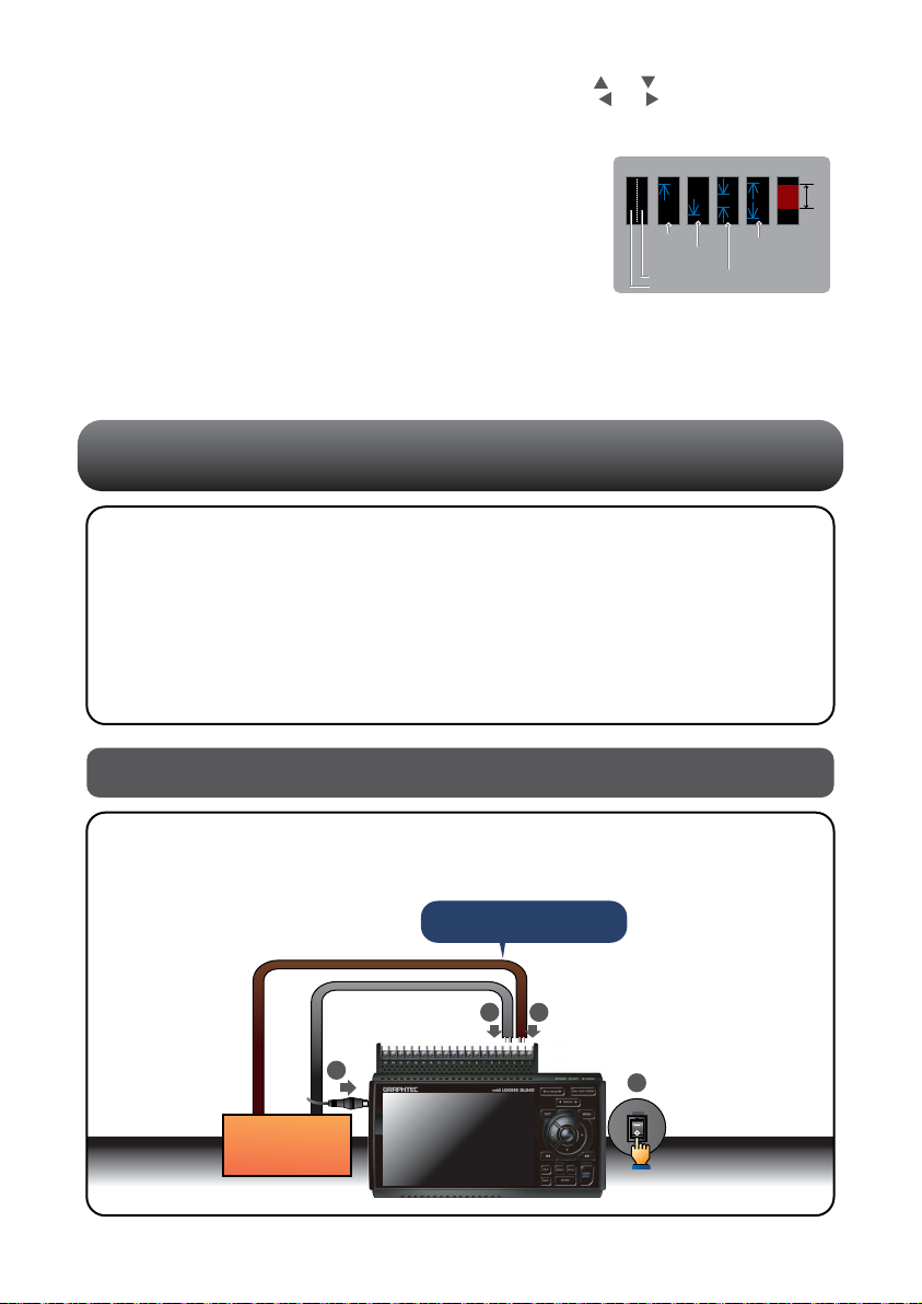
Measurement Procedure
In this section we will provide a simple explanation of the data capture procedure:
Preparations -> Setup -> Data Capture -> Data Replay.
Voltage measurement is performed here.
Purpose of data capture : To measure the temperature of the target objects
Temperature Range : T type Thermocouple, 100℃
Voltage range : 1V
Sampling interval : 1 sec
Data save destination : SD1 (SD CARD1)
1. Connect Thermocouple to the CH 1 terminal (Temperature).
2. Connect wire to the CH 2 terminal (Voltage).
3. Connect the AC power supply.
4. Turn on the power supply.
1.
Preparations : How to Make the Preparations Required for Data Capture
11
Quick settings
Alarm display area
Pen display
File name display area
Scale lower limit
Waveform display area
Scale upper limit
Data capture bar
13.
14.
15.
16.
17.
18.
19.
20.
Measurement
object
1
2
4
Connect securely!
3
Start side
Rriisg
tignegr Falling
tignegr
Within
the range
Outside
the range
Alarm rangeTrigger position
Stop side
: Displays items that can be easily set. The and keys can be used to
make a Quick settings item active, and the and keys to change the
values.
: Displays the status of the alarm output. (Red = alarm generated, white =
alarm not generated)
: Displays the signal positions, trigger
positions, and alarm ranges for each
channel. (see right figure)
: Displays the data capture file name during
the data capture operation.
When data is being replayed, the display
position and cursor information are
displayed here.
: Displays the lower limit of the scale of the
currently active channel.
: The input signal waveforms are displayed here.
: Displays the upper limit of the scale of the currently active channel.
: Indicates the remaining capacity of the capture media during data capture.
When data is being replayed, the display position and cursor information are
displayed here.
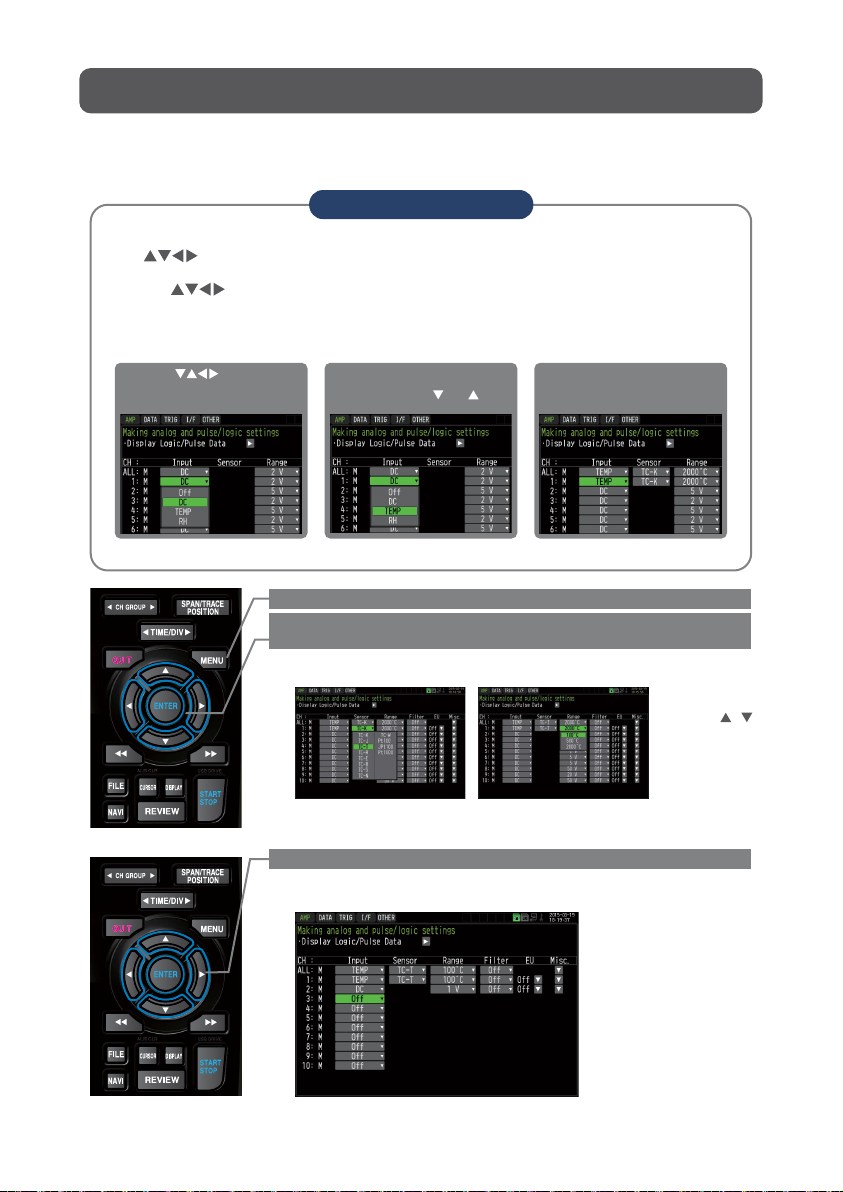
2. Setup : How to Make the Settings
12
Make the settings required for data capture. Here we will make only those settings
that are minimum requirement. The other settings will be not changed from the
factory default settings.
Points to Remember
Basic Setup Menu Operation
•Examples of selection menu operations (AMP screen)
(Note: Select "DC" for voltage measurement, and "Humidity" for humidity measurement.)
The , [ENTER], and [QUIT] keys are used to set the condition on the setup menu.
The current position of the cursor on the setup menu is displayed in green.
Use the keys to move the cursor. If you press the [ENTER] key at the cursor
position, a selection menu or a box of entering value for selected item is displayed.
If you press the [QUIT] key, the screen closes and the settings are canceled.
1. Use the keys to move
the cursor to the Input
parameter of CH 1 and then
press the [ENTER] key.
2. A selection menu is displayed
when the [ENTER] key is
pressed. Use the and keys
to select "TEMP."
3. Press the [ENTERv key to
confirm your selection.
Select with ,
and [ENTER] key.
1. Press the [MENU] key to display the setup menu screen.
3. Select "Off" for all the other channels.
2. Set Input to "TEMP" and Sensor to "TC-T" for CH1,
and set Input to "DC" and Range to "1V" for CH2.
(1) Move the cursor to CH1 "Sensor" and select "TC-T" and then move it to
"Range" and select “100°C” .
(1) Using the procedure described above, select "Off" for CH 3 to CH 10.
Use the [CH GROUP] key to switch to the CH11 to CH20 group.
(2) In the same way, move the cursor to CH2 "Input" and select "DC" and
then move it to "Range" and select "1V."

4. Press the [MENU] key and open the "DATA" menu.
Press the [MENU] key. Next, move the cursor to the “DATA” in the "MENU"
at the top.
5. Set the sampling interval to "1s".
Move the cursor to "Sampling" and then select "1s".
6. Set the Data Capture Destination to "SD memory card".
Here the "TEST" folder is created in the <SD1> , and then destination for the
captured data is set to the TEST folder.
(1) Move the cursor to the File Name parameter and then press the [ENTER]
key.
(2) Move the cursor to the <SD1> item in the following screen, press the
[ENTER] key.
(3) The file settings box shown in the following screen opens.
In the file box, set the file name to record in the SD memory card.
* The remaining memory capacity is
indicated in the <SD1> when the SD
memory card is mounted.
When the SD memory card is not
mounted, 0 Bytes is indicated.
13
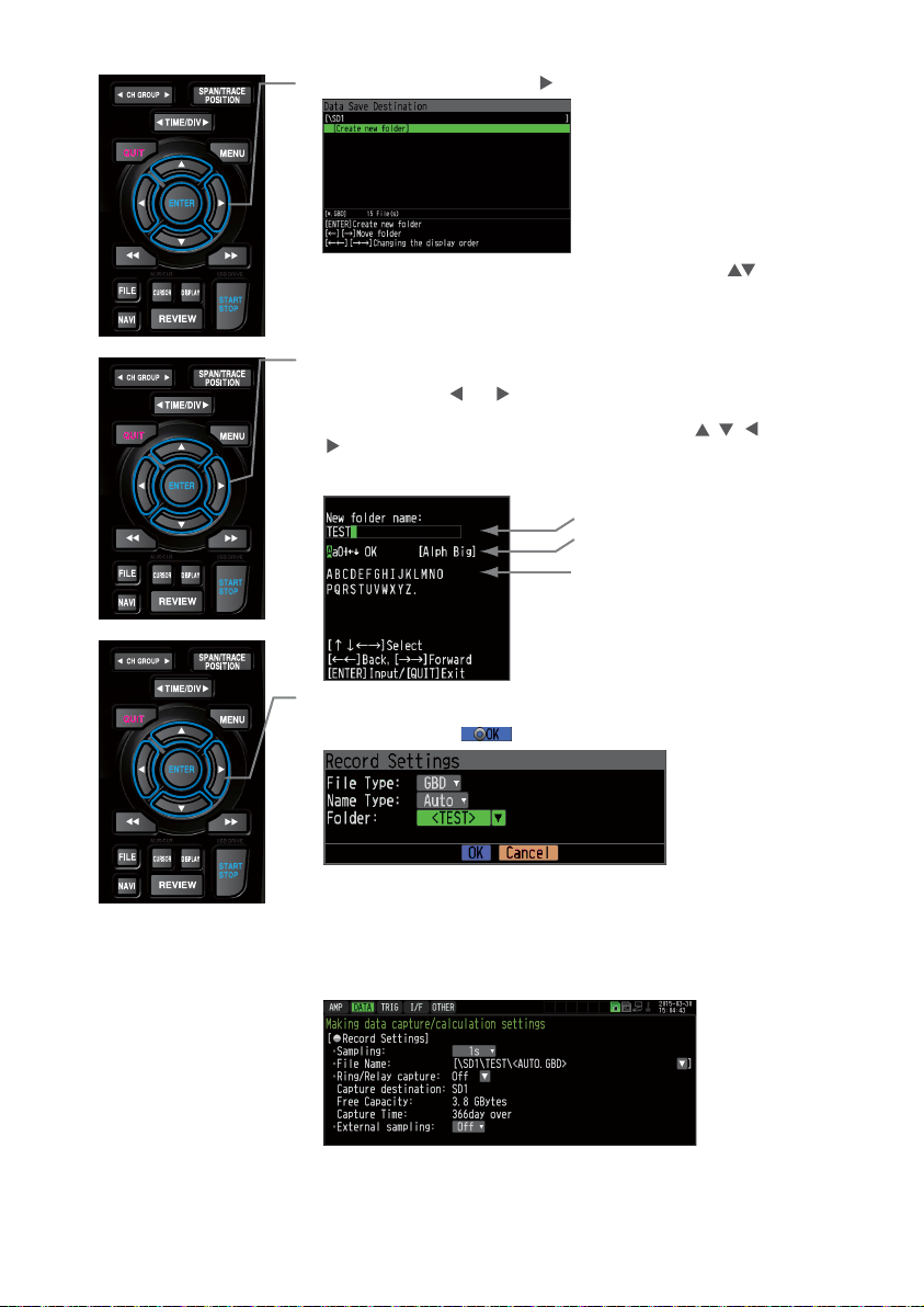
Move the cursor to the "Create New Folder" icon using the keys and
then press the [ENTER] key. The Input menu is displayed.
(4) Go to the "SD1" level using the key.
14
(5) A text input box is displayed. Let's create a folder named "TEST".
(1) In the text type select; delete; insert; confirm items, move the cursor
to the A using the and keys.
(2) The selected text is displayed.
In the text select, move the cursor to the text using the , , and
keys and then press the [ENTER] key.
Input "TEST", move the cursor to [OK] , and then press the [ENTER] key
to enter your setting.
(6) Select the "TEST" folder and then press the [ENTER] key to return to the
Capture setting screen.
(7) Move the cursor to and then press the [ENTER] key.
(8) Available space in specified memory device and time for data capture are
displayed in the lower part of the Record Settings menu.
The data capture time can be checked.
The data is recorded with the automatic file naming in the <TEST> folder
of the mounted SD memory card.
Minimum required setting for data capture is completed.
Text input box
(1) Select the text type, delete,
insert, confirm
(2) Select the character
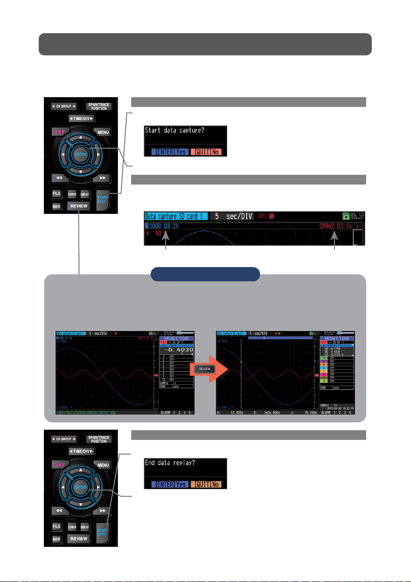
3. Data Capture : How to Capture Data
All of setting for the data capture have been set, capturing data can be started now.
During the data capture operation, let's also replay some data that was captured
previously.
1. Starting data capture
(1) Press the [START/STOP] key.
(2) A confirmation message is displayed.
2. Screen status during data capture
Once data capture has started, progress of data capture is shown.
The displayed time is counting up or down.
(3) Press the [ENTER] key to start data capture.
3. Stopping data capture
Press the [START/STOP] key to end the data capture operation.
(1) Press the [START/STOP] key.
(2) A confirmation message is displayed. Press the [ENTER] key.
(3) Data capture ends, and the GL840 goes into the Free Running status.
The operation of data capture is completed.
capturing message
elapsed time remaining time for data capture
(The indication becomes ++++ when the data capture time is 9999 hours or more.)
15
Points to Remember
Data can be replayed while being captured by pressing the [REVIEW] key.
Data can be replayed during the data capture operation from the beginning to the point that
has been captured.
During the replay, you can check arbitrary level values and such by moving the cursor.
You can return to the data capture screen by pressing the [REVIEW] key again.
4. Data Replay : How to Replay Captured Data
When data capture ends, data is automatically replayed.
The automatically replayed data is the data captured to the SD memory card which
has been set as the data capture destination.
Press the [QUIT] key to end the data replay operation.
Explanation of basic operation in the GL840 is completed.
The GL840 has many other convenient functions. Please refer the next five pages for
details.
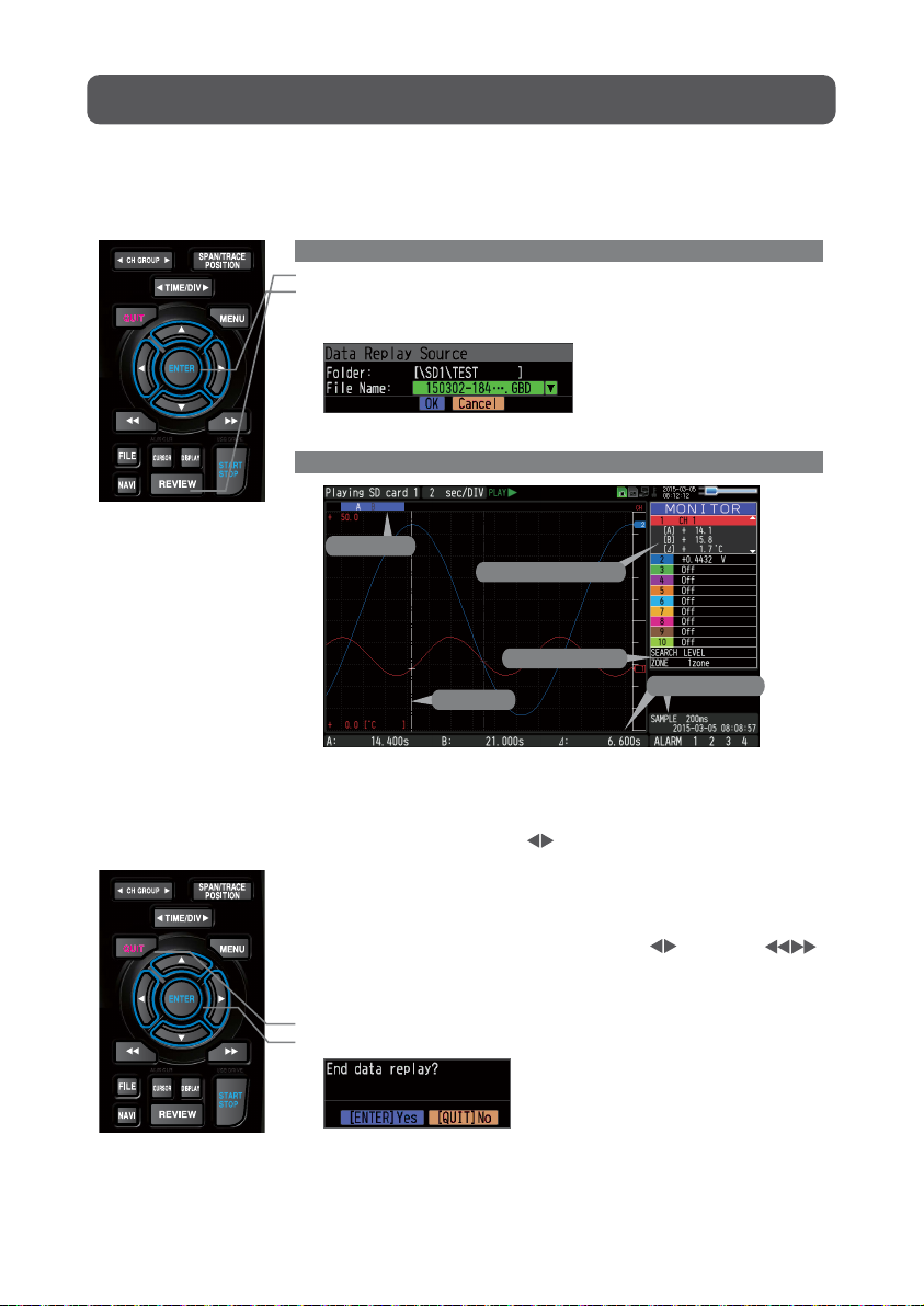
1. Selecting a file to replay
(1) Press the [REVIEW] key.
(2) Since the file you want to replay has the file name that was appended
automatically when the data was captured, move the cursor to the [OK]
button and then press the [ENTER] key.
(1) Scroll bar
(2) Level display area
(3) Quick settings
(4) Time display
(5) Cursor
2. Replay screen
(3) The Replay screen opens.
Press the [QUIT] key to end the data replay operation.
A confirmation message is displayed. Press the [ENTER] key.
Data replay ends, and the GL840 goes into the Free Running status.
16
5. Cursor
2. Level display area
3. Quick settings
4. Time display
1.Scroll bar
: Displays the position within the whole data and the
display width.
: Displays the levels of A and B cursors and the
difference between the A and B values.
: Use the keys to search the previous or next
level. (Note: Make search settings in the menu.)
: Displays the sampling interval and the time of the
cursor.
: Displays the cursor. (Note: Press the CURSOR key
to switch between A and B cursors.)
Move the cursor using the keys or the
keys.
Desired level values and time can be checked by
moving the cursor.

The GL840 has various functions that enable it to be used more effectively.
The selected three functions are described with details in the following.
Here data capture is started in the condition as "Start data capture when the
CH 1 temperature exceeds 20ºC".
(1) Press the [MENU] key and open the "TRIG" menu.
(2) Move the cursor to "Start Source" and select "Level".
(3) Press the [ENTER] key according to the “Level Settings” . The “Trigger
Level Settings” screen is displayed. Move the cursor to the "Mode"
parameter for the CH1, and then select "Hi".
1. Starting data capture
Trigger functions can be used to control the timing of the start of a data
capture operation, and the timing of the end of a data capture operation.
Convenient Functions
Trigger Functions to Control Data Capture Start/Stop Operations
Points to Remember
For example...
The trigger function performs operations such as the following:
• Start data capture when the voltage exceeds 1 V
• Stop data capture at 1:00 pm
• Perform control via external input
The example of the data capture start in the temperature setting conditions is
described below.
17
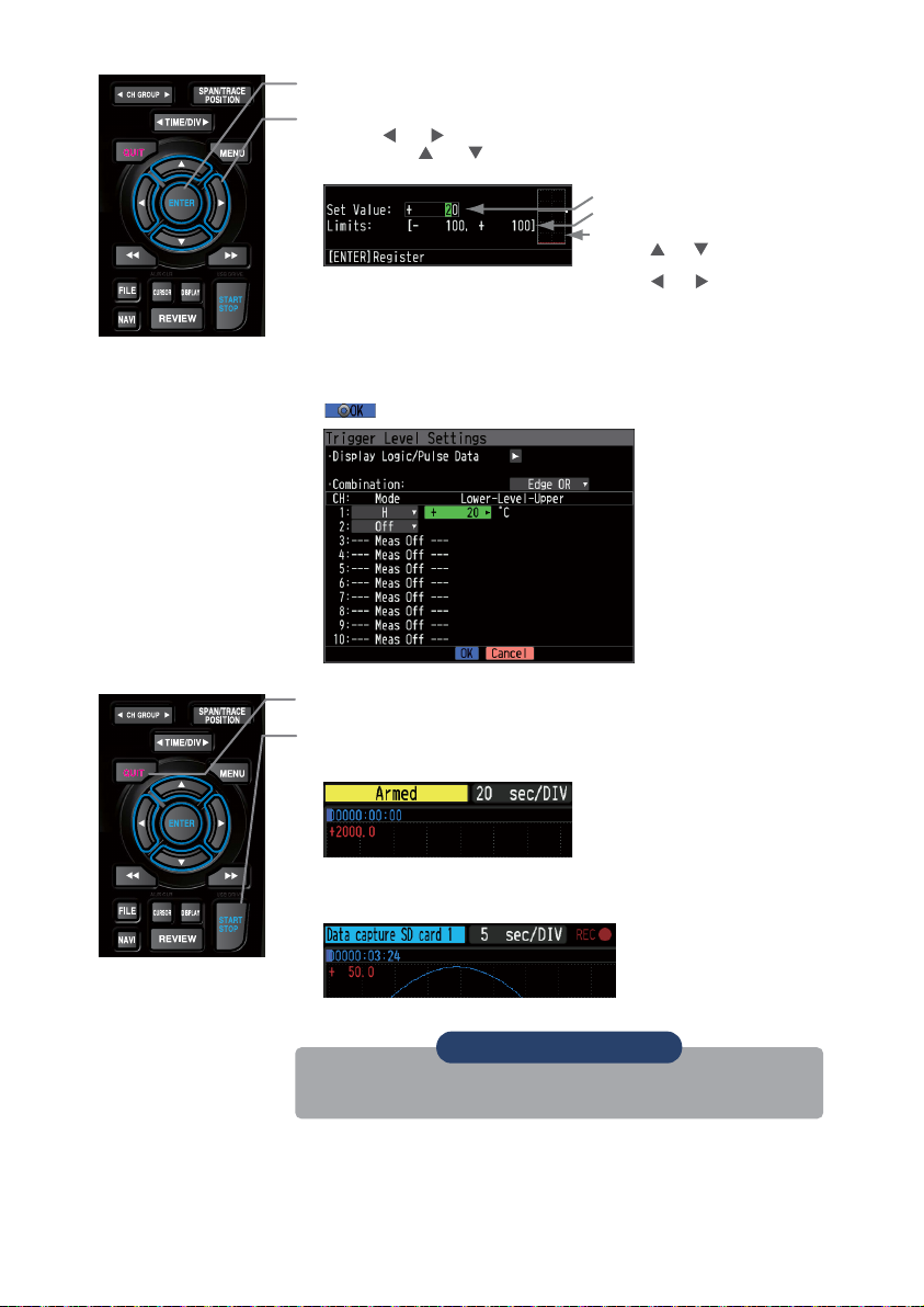
(4) Move the cursor to the "Level" parameter next to the "Mode" parameter
and then press the [ENTER] key.
(5) The input box shown in the following screen is displayed. Select "20".
Use the and keys to move to the cursor to the second digit from the
right, and the and keys to change the value. Press the [ENTER]
key.
(7) The screen returns to the TRIG menu screen. Press the [QUIT] key to
return the GL840 to the Free Running status.
(8) Press the [START/STOP] key to start data capture.
If the trigger condition has not been satisfied, the GL840 goes into the
"Armed" status as shown on the following screen.
(6) When the screen changes to the following screen, move the cursor to the
button and then press the [ENTER] key.
When the trigger condition is satisfied, the recording is started after the
display is changed to the “Data capture SD card 1” .
Numerical value input box
Lower and upper limit for setting.
Waveform area for confirmation Lower
•Use the and keys to change the
values.
•Use the and keys to move the
digit.
•Use the [ENTER] key to enter the
value.
•Use the [QUIT] key to cancel the
setting.
18
Points to Remember
The trigger of this trigger function can be set easily from the "Easy trigger
setting" menu in the navigation displayed by pressing the [NAVI] key.

1. Starting data capture
Trigger functions can be used to control the timing of the start of a data
capture operation, and the timing of the end of a data capture operation.
Span, Position and Trace Functions to Adjust the Waveform Display
Points to Remember
The span, position and trace operations can be performed while the GL840 is in
the Free Running status, while it is capturing data, and while it is replaying data.
The changes are applied to the displayed data only, the change is not affected
to the captured data.
1. How to Make a Span setting
The Span parameter is used to adjust the amplitude of the input waveform.
This setting is made in the aforementioned Free Running status.
(1) Set the displayed span for CH 1 to 100ºC.
(2) Press the [SPAN/TRACE/POSITION] key to select the SPAN mode.
2. How to make a Position setting
The Position parameter is used to adjust the position of displayed waveform
that is set by the upper and lower values.
(1) Press the [SPAN/TRACE/POSITION] key to select the POSITION mode.
(2) Use the and keys to make CH 1 active (enlarged display).
(3) Use the and keys to set the Position value to "+90ºC to -20ºC".
When this setting has been changed, the waveform screen scale will be
set to "+90ºC to -20ºC".
(3) Use the and keys to make CH 1 active (enlarged display).
(4) Use the and keys to change the Span value. Here the value for
span is set to 110ºC.
When this setting has been changed, the waveform screen scale will be
set to "+110.0 to +0.0".
Points to Remember
The currently selected mode (SPAN,
POSITION or TRACE) can be checked by
looking at the "Waveform Operation Display
Area".
3. How to make a Trace setting.
The Trace parameter can be used to specify the selected waveform to be
visible or invisible on the display.
(1) Press the [SPAN/TRACE/POSITION] key to select the TRACE mode.
(2) Use the and keys to make CH 1 active (enlarged display).
(3) Use the and keys to select Off.
When this setting has been changed, the CH 1 waveform is not
displayed.
19
Other manuals for GL840
5
Table of contents
Other GRAPHTEC Recording Equipment manuals


Popular Recording Equipment manuals by other brands


ETA Systems
ETA Systems ETA-ECS3 manual

Balluff
Balluff BNI IOW-560-W01-K022 user guide

Mitsubishi Electric
Mitsubishi Electric DX-TL5000E Operation manual

GRASS VALLEY
GRASS VALLEY K2 DYNO - quick start guide

DirectOut Technologies
DirectOut Technologies ANDIAMO Hardware guide

elsner elektronik
elsner elektronik KNX B4 Universal installation instructions