SKF IF-105 Manual

IF1051AEN.doc 03.01.2013 Rev. 1A
IF-105 user interface
(Original operating and maintenance instructions)

IF1051AEN.doc 03.01.2013 Rev. 1A
TABLE OF CONTENTS
1 General information .....................................................................................................................................1
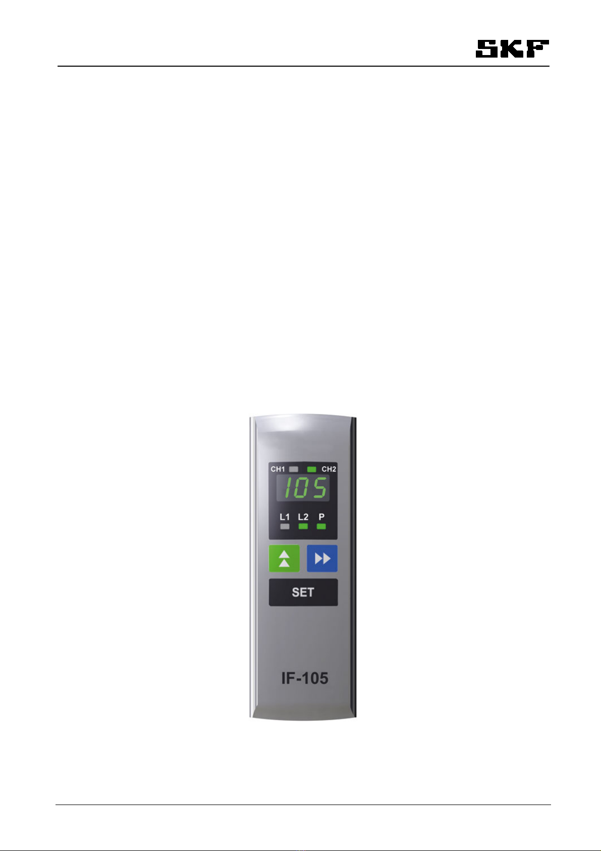
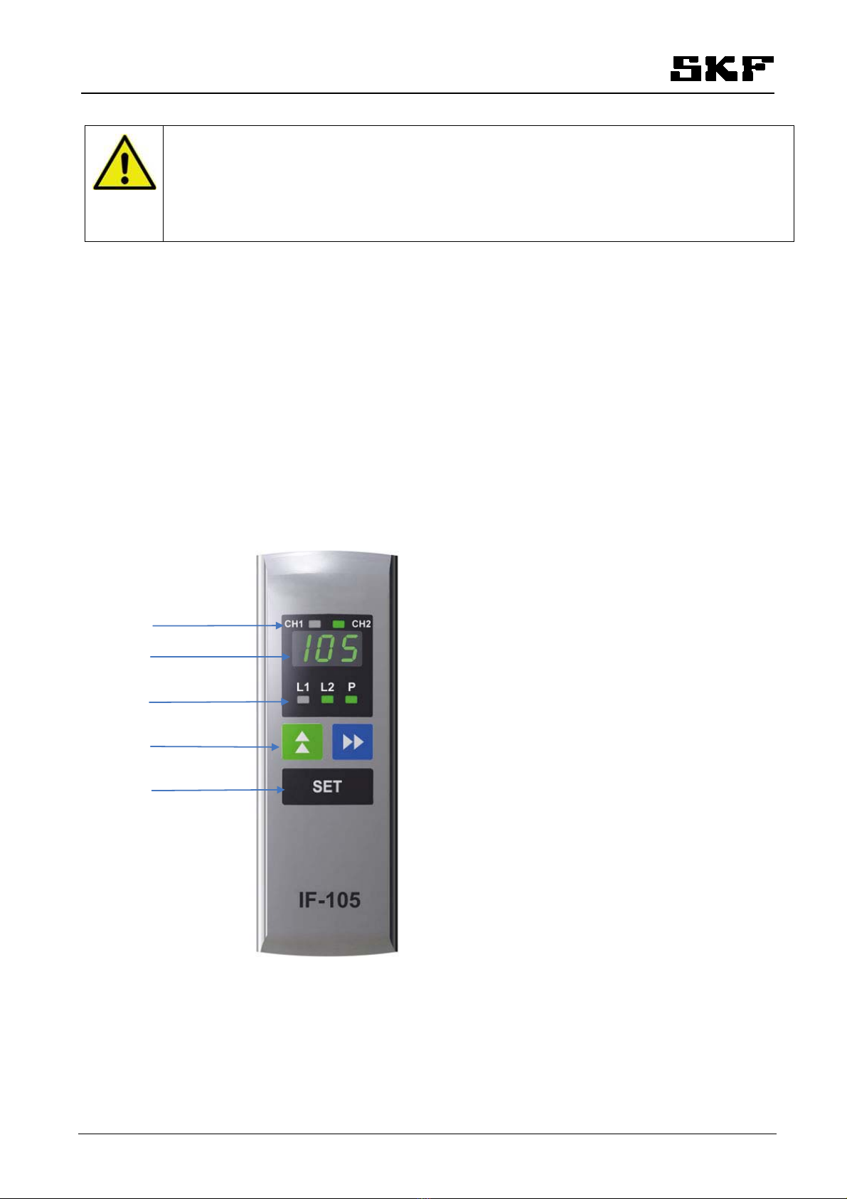
2 Design..........................................................................................................................................................1
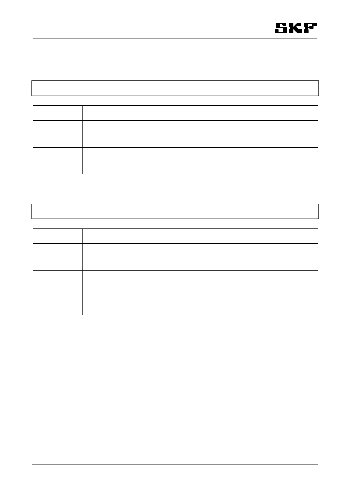
2.1 LED-signals for channels...........................................................................................................................................................2
2.2 LED-signals for operation .........................................................................................................................................................2
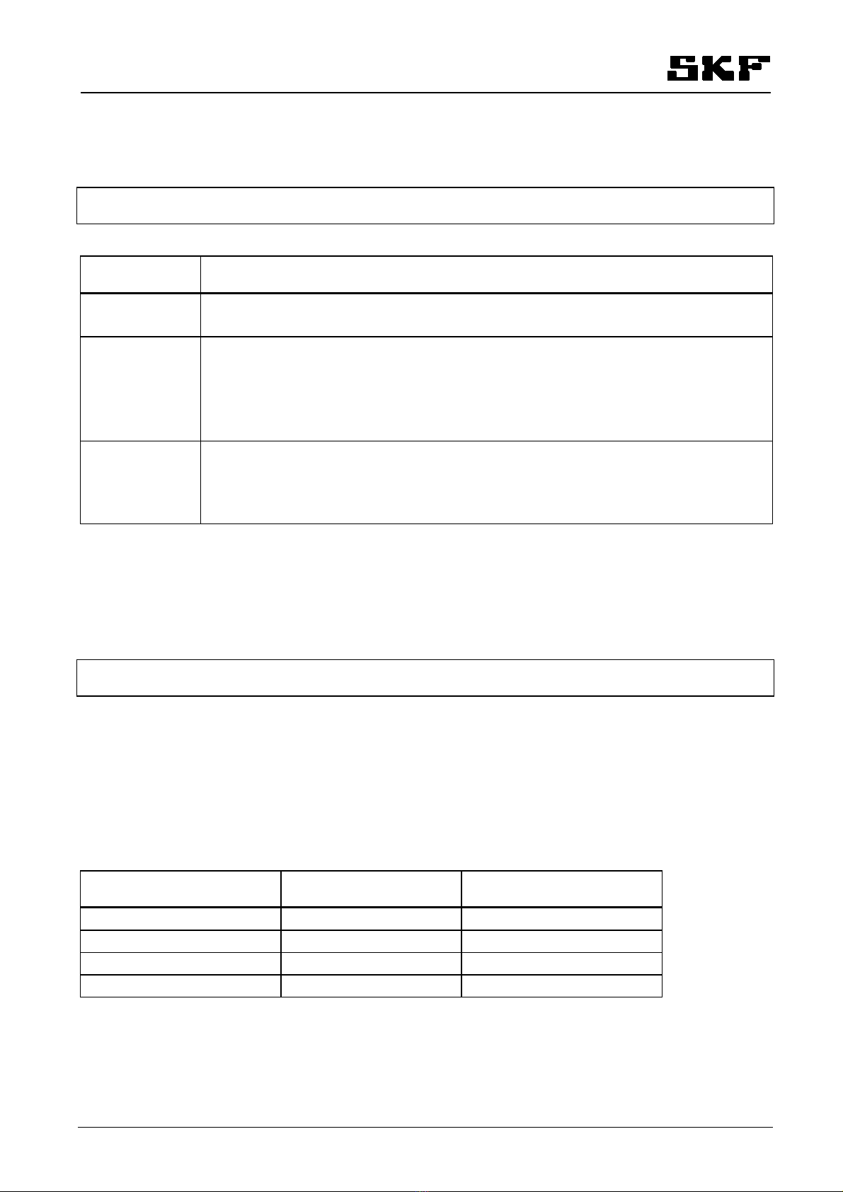
2.3 Buttons.........................................................................................................................................................................................3
2.4 Display..........................................................................................................................................................................................3
3 Operation.....................................................................................................................................................4
3.1 Normal mode ..............................................................................................................................................................................4
3.1.1 Functions..............................................................................................................................................................................4
3.1.2 Phase codes for normal mode and alarm mode ............................................................................................................5
3.1.3 Normal mode displays, MonoFlex and and DuoFlex lubrication systems ...................................................................6
3.1.4 Normal mode displays, ProFlex lubrication system .......................................................................................................7
3.1.5 Pressure and pulse displays for lines...............................................................................................................................8
3.2 Power failure...............................................................................................................................................................................8
3.3 Alarms..........................................................................................................................................................................................8
3.3.1 Low level alarm...................................................................................................................................................................9
3.3.2 Pressure alarm, MonoFlex and DuoFlex lubrication systems.......................................................................................9
3.3.3 Pulse alarm, ProFlex lubrication system .........................................................................................................................9
3.3.4 Alarm from SKF Doser monitor -doser operation indicator.........................................................................................9
3.3.5 Alarm from the air pressure switch of the grease spray system .............................................................................. 10
3.3.6 Warning message for pump change (doubled pumping center/Dualset)................................................................. 10
3.4 Manual operation..................................................................................................................................................................... 10
4 Settings .....................................................................................................................................................11
4.1 General...................................................................................................................................................................................... 11
4.2 Entering password................................................................................................................................................................... 11
4.3 Entering settings...................................................................................................................................................................... 11
4.3.1 Lubrication cycle counter................................................................................................................................................ 11
4.3.2 Lubrication cycle............................................................................................................................................................... 12
5 Technical specification................................................................................................................................12
5.1 Technical data.......................................................................................................................................................................... 12
5.2 Symbols .................................................................................................................................................................................... 12
6 Contact information....................................................................................................................................12

IF1051AEN.doc 03.01.2013 Rev. 1A 1 (12)
Warning Read and follow the safety precautions and general instructions in this manual and
also in the SKF manual
"Safety and general instructions for lubrication systems."
Failure to follow these
instructions could result in serious injury or damage to the lubrication system or the equipment that is
lubricated.
1 General information
IF-105 is the user interface for the internal control unit of SKF Maxilube hydraulic part and for the SKF ST-1240-IF
control center.
Lubrication programming, alarm resetting and lubrication event monitoring can be performed with the user interface.
2 Design
The IF-105 user interface includes a display (pos. 1), LED-signals for lubrication lines and pressurization (pos. 2),
browsing buttons (pos. 3), a setting/function button (SET) (pos. 4) and LED-signals for lubrication channels (pos. 5).
5
1
2
3
4

IF1051AEN.doc 03.01.2013 Rev. 1A 2 (12)
2.1 LED-signals for channels
Note! LED-signals CH1 and CH2 for lubrication channels are in use only in systems with two channels.
LED-signal Description
CH1 Red LED-signal is lit, when channel 1 is in alarm mode.
Green LED-signal is lit, when channel 1 is in normal mode.
LED-signal is blinking when channel 1 is selected on the display.
CH2 Red LED-signal is lit, when channel 2 is in alarm mode.
Green LED-signal is lit, when channel 2 is in normal mode.
LED-signal is blinking when channel 2 is selected on the display.
2.2 LED-signals for operation
Note! The LED-signals indicate the operation of the channel which is selected on the display.
LED-signal Description
L1 Green LED-signal is lit, when main line 1 is pressurized.
Green LED-signal is lit during interval, when main line 1 has been pressurized last.
Red LED-signal is blinking, when main line 1 is in pressure alarm mode.
L2 Green LED-signal is lit, when main line 2 is pressurized.
Green LED-signal is lit during interval, when main line 2 has been pressurized last.
Red LED-signal is blinking, when main line 2 is in pressure alarm mode.
PGreen LED-signal is lit, when the pressurization phase is in progress.
Red LED-signal is blinking, when the pumping center is in low level alarm mode.

IF1051AEN.doc 03.01.2013 Rev. 1A 3 (12)
2.3 Buttons
Note! The buttons affect only the channel which is selected on the display.
Button Description
In normal mode, the button is used to browse set values on the display.
In setting mode, the button is used to change the value on the display.
In normal mode in a MonoFlex- and a DuoFlex-system the button is used to browse the
pressure displays of the lines.
In normal mode in a ProFlex system the button is used to go to the pulse counter display.
In setting mode, the button is used to move to the next character of the display.
When browsing the set values, the button is used to return to normal mode.
SET In normal mode, the button is used to start extra lubrication, to stop pressurization or reset an
alarm.
In setting mode, the button is used to save the changed value.
When browsing the set values, the button is used to go to the setting mode.
When a button is pressed, all green LED-signals are lit for a moment. This indicates that the information about a
button being pressed has been transmitted forward.
2.4 Display
Note! The display indicates the operation of the channel which is selected on the display.
User interface has a display of 3 characters and 3 decimal points.
The display shows the time and, in pressure transmitter operation, also pressure.
Time and pulse display
The set value for the lubrication cycle and the elapsed interval are displayed as hours and minutes. Decimal point is
used to separate hours and minutes.
Time displayed Display format Example
0 min - 59 min H.MM 12 min = 0.12
1 h - 9 h 59 min H.MM 1 h 20 min = 1.20
10 h - 99 h 50 min HH.M 12 h 50 min = 12.5
100 h - 999 h HHH. 120 h = 120.
The set value for the maximum pressurization time and elapsed pressurization time are displayed as seconds without
the decimal point.
The set pulse amount and the counted pulses are displayed as integers, without a decimal point.

IF1051AEN.doc 03.01.2013 Rev. 1A 4 (12)
3 Operation
3.1 Normal mode
3.1.1 Functions
Display power saving mode
In normal mode, the display shifts to power saving mode when no buttons have been used for ten (10) minutes. In
power saving mode only the decimal points are blinking on the display. Lubrication events are performed according to
the set values. The display returns to normal mode if any button is pressed or if there is an alarm.
Interval counting
In normal mode the display shows the time elapsed since the last pressurization as hours and minutes. Green LED-
signal for line L1 or L2 shows which line has been pressurized last.
Interval time is counted always, except when
•channel is in alarm mode
•interlocking switch of the channel is closed
•channel is closed (maximum pressurization time = 0)
Pressurization
Pressurization time is displayed as seconds. Green LED-signal for line L1 or L2 shows the line to be pressurized. Green
LED-signal Pindicates that pressurization is in progress.
Pressurization can be stopped with the SET button.
Pressurization time display and setting can be changed from seconds to minutes with factory setting parameter Prt.
When the pressurization time is displayed as minutes all the decimal points are lit on the display.
Extra lubrication
Extra lubrication can be started if the channel is not currently in alarm mode, closed or pressurizing.
Extra lubrication is started in normal mode with the SET button, when the display shows the time elapsed since the
last pressurization.
In a DuoFlex lubrication system both lines are pressurized once. The next line in the set pressurization sequence is
pressurized first. In a MonoFlex and a ProFlex lubrication system the line is pressurized once.
Extra lubrication can be stopped with the SET button.
In pressure transmitter operation, the line pressure discharge is measured. New pressurization starts only after
pressure in the lines is below the set low limit value.
In pressure switch operation, the system waits for line pressure discharge. New pressurization starts only after the set
delay time.
During pressure discharge phase code dC is displayed.

IF1051AEN.doc 03.01.2013 Rev. 1A 5 (12)
3.1.2 Phase codes for normal mode and alarm mode
In normal or alarm mode, the phase code corresponding to the program phase is displayed.
Phase code Description
dC Pressure discharge waiting time
(disCharge)
Loc Interlocking switch is closed
(Locked)
OFF The channel is closed
AGr Lubricant reservoir low level alarm
(Alarm, Grease)
ALP Pressure low alarm
(line pressure does not rise high enough during pressurization time)
(Alarm, Low Pressure)
Pulse amount alarm in a ProFlex system
(Alarm Low amount of Pulses)
AHP Pressure high alarm
(line pressure is not low enough when pressurization phase starts)
(Alarm, High, Pressure)
AIn Alarm from doser operation indicator (SKF Doser monitor).
The code is displayed only if SKF Doser monitors are in use.
(Alarm, Indicator)
Air Alarm from the air pressure switch of the grease spray system.
The code is displayed only if air pressure switch is in use.
(Alarm, Air)
APC Warning message for pump change when doubled pumping center (Dualset) is in use.
(Alarm, Pump Changed)

IF1051AEN.doc 03.01.2013 Rev. 1A 6 (12)
3.1.3 Normal mode displays, MonoFlex and and DuoFlex lubrication systems
Normal mode displays, which show the set values for the lubrication program, can be browsed with the -button.
Display codes change in the following order when -button is pressed.
Display code Description
CH The lubrication channel selected on the display. The code is in use only in systems with two
(2) channels. Press the SET button to go to another channel when the code is displayed.
(Channel)
Cou Lubrication cycle counter.
(Cycle Counter)
Counter reading is added by one unit when lubrication ends. Decimal point is used to
separate thousands.
CLubrication cycle setting value as time [h.mm] or pulses depending on the factory setting
parameter CYC. Can be set between 0 min – 999 h or 000…999 pulses.
(Lubrication Cycle)
PMaximum pressurization time set value [s]. Can be set between 0 s – 999 s.
Set value can be changed to minutes with factory setting parameter Prt.
Can be set between 0 min – 999 min.
(Lubrication, Pressurization time)
PLo Low limit pressure set value [bar/psi]. Can be set between 0-200 bar/0-2900 psi.
(Pressure, Low limit)
Code is in use only in pressure transmitter operation.
PHi High limit pressure set value [bar/psi]. Can be set between 0-200 bar/0-2900 psi.
(Pressure, High limit)
Code is in use only in pressure transmitter operation.
dEL Pressure discharge delay multiplier [n]
(DELay) Delay = P * n [s]
Code is in use only in pressure switch operation.
HL Manual operation setting
On: manual operation mode
OFF: automatic mode
PU Pump in use when doubled pumping center (Dualset) is in use:
1: Pump 1 is in use.
2: Pump 2 is in use.
This parameter is visible only when the factory setting parameter dUA has been set to YES.
Decimal points are used to separate thousands on lubrication cycle counter reading. Counter max. reading is 49.9 =
49 999.
Depending on the factory setting parameter Pre, the pressure unit on the display is bar or psi. In a psi reading decimal
points are used to separate thousands. For example 1.02 = 1020 psi.

IF1051AEN.doc 03.01.2013 Rev. 1A 7 (12)
3.1.4 Normal mode displays, ProFlex lubrication system
Normal mode displays, which show lubrication program set values, can be browsed with the -button.
Display codes change in the following order when -button is pressed.
Display code Description
CH The lubrication channel selected on the display.
Press the SET-button to go to another channel when the code is displayed.
Cou Lubrication cycle counter.
(Cycle Counter)
Counter reading is added by one unit when lubrication ends. Decimal point is used to
separate thousands.
CLubrication cycle setting value as time [h.mm] or pulses depending on the factory setting
parameter CYC. Can be set between 0 min – 999 h or 000…999 pulses.
(Lubrication Cycle)
PMaximum pressurization time set value [s]. Can be set between 0 s – 999 s.
Set value can be changed to minutes with factory setting parameter Prt.
Can be set between 0 min – 999 min.
(Lubrication, Pressurization time)
PP1 The pulse count setting (PP1) can be 000…999.
If PP1 is set as 0, pressurization takes the maximum pressurization time. The pulse sensor
does not need to be connected. Alarms will not be received, except for the low limit alarm.
(Pulses per 1pressurization)
HL Manual operation setting
On: manual operation mode
OFF: automatic mode
PU Pump in use when doubled pumping center (Dualset) is in use:
1: Pump 1 is in use.
2: Pump 2 is in use.
This parameter is visible only when the factory setting parameter dUA has been set to YES.
Decimal points are used to separate thousands on lubrication cycle counter reading. Counter max. reading is 49.9 =
49 999.

IF1051AEN.doc 03.01.2013 Rev. 1A 8 (12)
3.1.5 Pressure and pulse displays for lines
Pressure transmitter operation
In pressure transmitter operation, line pressure displays can be selected with the -button. Pressing the button will
show the pressure display for line 1 first. Code P1 and the pressure display for line 1 are displayed in turns. Pressing
the button again will show the pressure display for line 2. Code P2 and the pressure display for line 2 are displayed in
turns. If line 2 does not exist, the program returns to display the phase code. From the pressure display for line 2, the
program returns to display the phase code by pressing the -button. The display returns the phase code
automatically to the display after 4 minutes if no buttons have been used.
If a signal from the pressure transmitter is not detected, code _ _ _ is displayed.
Pressure switch operation
In pressure switch operation, the status of the pressure switches of the lines can be selected with the -button.
Pressing the button will display the status of the pressure switch for line 1 first. Code P1 and the status of the
pressure switch for line 1 are displayed in turns. Pressing the button again will display the status of the pressure
switch for line 2. Code P2 and the status of the pressure switch for line 2 are displayed in turns. The display returns
the phase code automatically to the display after 4 minutes if no buttons have been used.
The status closed contact of the pressure switch is displayed with code on and the status open contact with code oF.
Pulse counter display in the ProFlex system
Counted sensor pulses can be selected on the display with the -button. Code P1 and the pulse counter of the
selected channel are displayed in turns. -button is used to return to the time display.
3.2 Power failure
The set values and program status are preserved in the memory also during power failures. Once the power is back
on, the operation will resume from the status it was in before power failure occurred. Pressurization that may have
been interrupted restarts for the same line. The interval time is not counted during power failures.
3.3 Alarms
System with one (1) channel:
•The system is in alarm mode when the red LED-signal for line L1, line L2 or pressurization Pis blinking.
System with two (2) channels:
•The system is in alarm mode when the red LED-signal for channel CH1 or CH2 is lit.
•When the channel selected on the display is in alarm mode, the red LED-signal for line L1, line L2 or
pressurization Pis blinking.

IF1051AEN.doc 03.01.2013 Rev. 1A 9 (12)
3.3.1 Low level alarm
The channel triggers a low level alarm, stops pressurization and goes into alarm mode, if the lubricant reservoir is
empty. This means that the reservoir’s low level switch is closed. Code AGr is blinking on the display and the red LED-
signal Pfor pressurization is blinking. Pressurization will restart for the same line when the low level switch opens and
the alarm has been reset by pressing the SET-button.
3.3.2 Pressure alarm, MonoFlex and DuoFlex lubrication systems
The channel triggers a pressure alarm and goes into alarm mode, if the line pressure is not low enough when
pressurization phase starts or if the line pressure does not rise high enough during pressurization time.
Alarm, high pressure
If the line pressure is not low enough at the beginning of the pressurization phase, code AHP is blinking on the display
and the red LED-signal L1 or L2 of the line that triggered the alarm is blinking.
In pressure transmitter operation an alarm is triggered, if the line pressure is above the set low limit when
pressurization starts. Pressurization will restart for the same line when the pressure level is below the low limit value
and the alarm has been reset by pressing the SET-button.
In pressure switch operation an alarm is triggered, if the pressure switch is closed when the pressurization starts.
Pressurization will restart for the same line when the pressure switch opens and the alarm has been reset by pressing
the SET-button.
Alarm, low pressure
If the pressure in the line does not rise high enough during pressurization time, code ALP is blinking in the display and
the red LED-signal L1 or L2 of the line that triggered the alarm is blinking.
In pressure transmitter operation an alarm is triggered, if the line pressure does not reach the set high limit within
the set maximum pressurization time. Pressurization will restart for the same line when the alarm has been reset by
pressing the SET-button.
In pressure switch operation an alarm is triggered if the pressure switch of the line does not close within the set
maximum pressurization time. Pressurization will restart for the same line when the alarm has been reset by pressing
the SET-button.
3.3.3 Pulse alarm, ProFlex lubrication system
The channel triggers a pulse alarm ALP (Alarm Low amount of Pulses) and goes into alarm mode if the pulse amount
is not reached within the set maximum pressurization time.
3.3.4 Alarm from SKF Doser monitor -doser operation indicator
The SKF Doser monitors are in use when factory settings parameter LGI has been set in status YES.
An alarm will be triggered when the SKF Doser monitor does not recognize doser operation during a lubrication cycle.
Code AIn is displayed. Lubrication continues normally despite the alarm. This feature is different from other alarms.
The alarm can be reset with the SET-button.

IF1051AEN.doc 03.01.2013 Rev. 1A 10 (12)
3.3.5 Alarm from the air pressure switch of the grease spray system
Air pressure control is in use when factory settings parameter AC has been set in status YES.
Note! In a ProFlex system, the channel spray control starts always when the pump is running. The pump
stops when the pulse amount has been reached. The spray control remains on for 10 seconds.
An alarm is triggered if the air pressure switch is not open when pressurization starts or closed when pressurization
has stopped. Code Air is displayed. Pressurization will restart for the same line when the alarm has been reset by
pressing the SET-button.
3.3.6 Warning message for pump change (doubled pumping center/Dualset)
When doubled pumping center (Dualset) is in use, a warning message APC is displayed when the pump has been
changed automatically. Lubrication continues normally despite the warning message. It can be reset with the SET-
button. Alarm output is not activated in this case.
3.4 Manual operation
Go to manual operation mode in the selected channel by setting the parameter HL in status On.
Return to automatic operation mode as follows:
•set the parameter HL in status OFF
or
•automatically when 60 minutes have elapsed since going into manual operation mode
or
•restart SKF Maxilube hydraulic part or SKF ST-1240-IF control center
In manual operation mode SET-button is used to:
•start pumping
•stop pumping
•shift pumping to another line
The lubrication program keeps the pressure in the set high limit value in the line being pumped. The oil lubrication
system (lubrication system operation mode O1 or O2) and ProFlex-system have no pressure monitoring.

IF1051AEN.doc 03.01.2013 Rev. 1A 11 (12)
4 Settings
4.1 General
Set values are lubrication channel basic values, for example lubrication cycle and maximum pressurization time. Set
values are channel specific.
All settings are password-protected.
4.2 Entering password
1Select the code for the setting to be changed on the display with the -button.
2Press the SET-button.
3Display shows code PPP.
4In a moment the first character of the display starts to blink.
5Select with the -button the first number of the password on the display.
6Move to the next character with the -button.
7When all three numbers of the password have been entered, press the SET-button.
8Once the password has been entered correctly, code ACC is displayed and the set values can be changed during
the next 10 minutes.
9If the password has not been entered correctly, code Err is displayed and the display returns to normal mode.
Note! Password for set values is 105.
4.3 Entering settings
1Select the code for the setting to be changed on the display with the -button.
2Press the SET-button.
3The first number of the value to be set is blinking on the display.
4Select the desired number with the -button on the display.
5Move to the next character with the -button.
6The set value is saved in the memory with the SET-button.
7Exit setting mode with the -button. The display returns to normal mode automatically after 4 minutes if no
buttons have been used.
4.3.1 Lubrication cycle counter
Lubrication cycle counter can be reset when needed.
1Select code Cou for the lubrication cycle counter on the display with the -button.
2Reset the counter with the SET-button.

IF1051AEN.doc 03.01.2013 Rev. 1A 12 (12)
4.3.2 Lubrication cycle
Lubrication cycle set value is displayed as hours and minutes. Decimal point is used to separate hours and minutes.
Decimal point of the set value can be moved as follows.
1Select the code for the setting to be changed on the display with the -button.
2Press the SET-button.
3Set the desired value with the - and -buttons.
4Press the -button.
5The decimal point starts to blink.
6Move the decimal point to the desired location with the -button.
7The set value is saved in the memory with the SET-button.
5 Technical specification
5.1 Technical data
Value Unit Description
-10…+50
14…122
°C
°F
Operating temperature range
45 x 140 x 17
(w x h x d)
mm Dimensions
Polycarbonate Material, casing
IP67 Protection class
5.2 Symbols
IF-105 Abbreviation Description
IF: IF Interface
105: 105 model
6 Contact information
Oy SKF Ab
P.O. Box 80 (Teollisuustie 6)
FI-40951 MUURAME
FINLAND
Tel. +358 207 400 800
Fax. +358 207 400 899
www.skf.com
Table of contents
Other SKF Recording Equipment manuals