3
TABLE OF CONTENTS
1. GENERAL
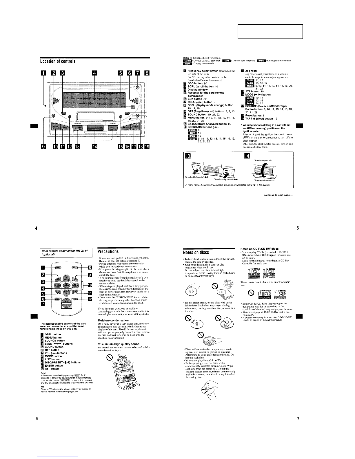
Location of Controls............................................................... 4
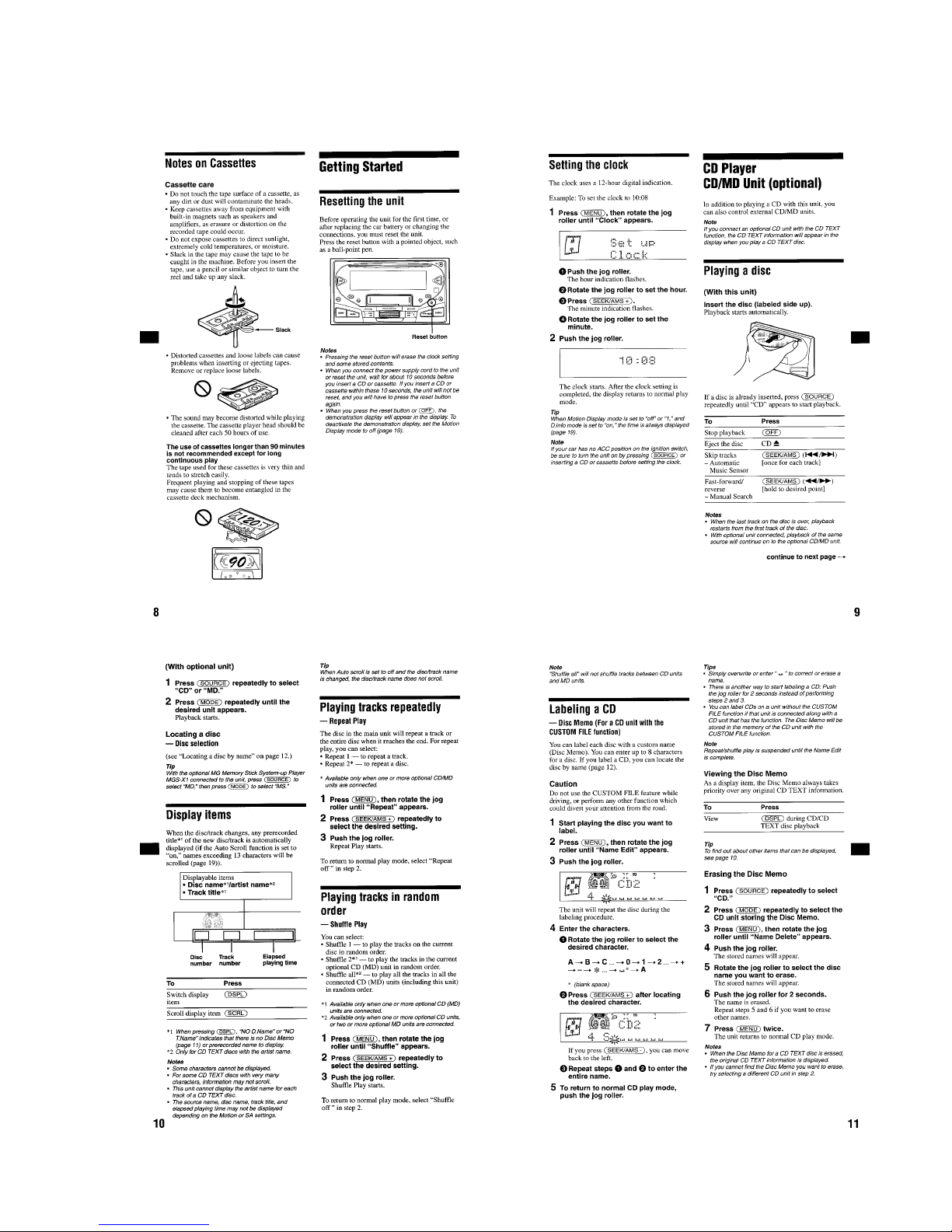
Getting Started........................................................................ 5
CD Player ............................................................................... 5
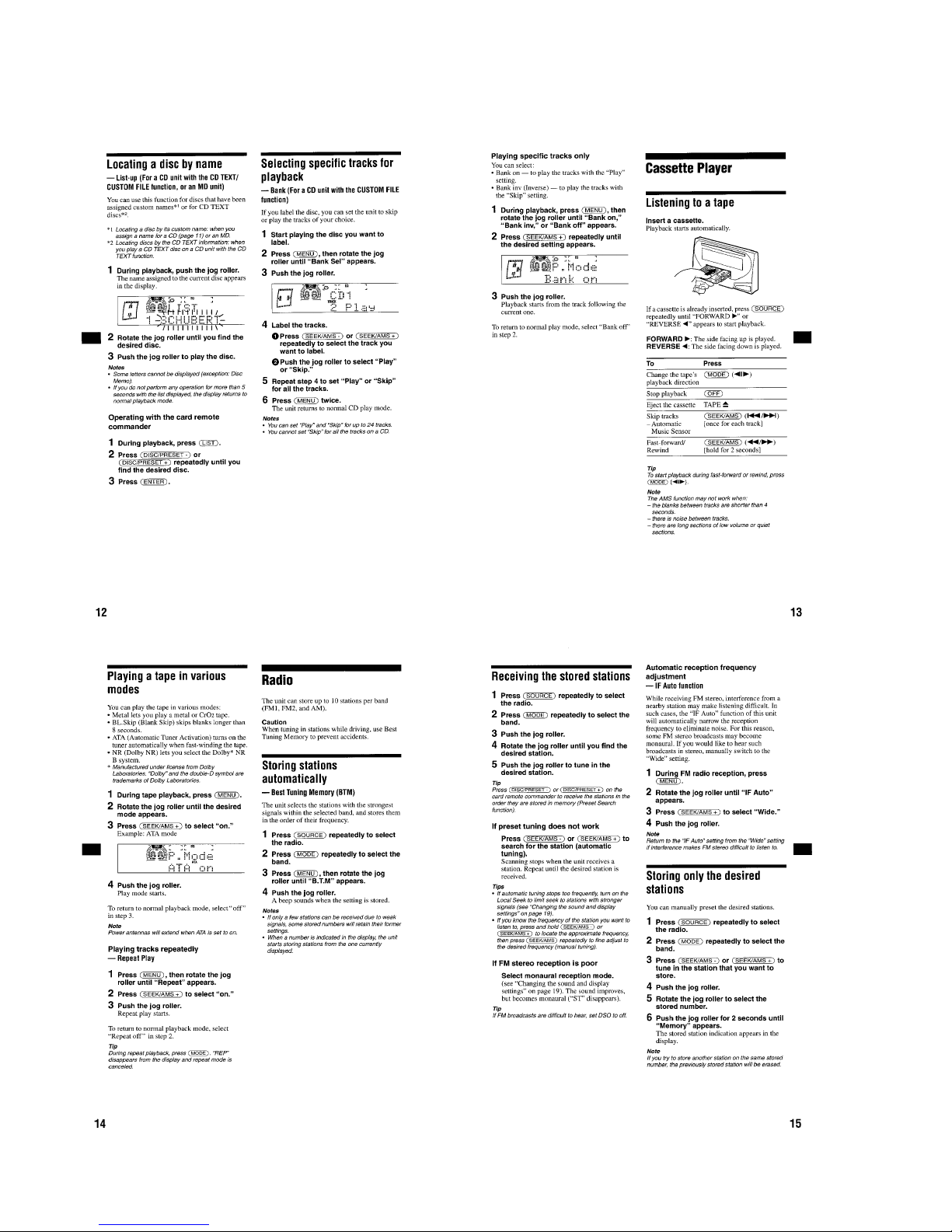
Cassette Player ....................................................................... 6
Radio ...................................................................................... 6
Other Functions ...................................................................... 7
Connections ............................................................................ 9
2. DISASSEMBLY
2-1. Front Panel Assy .............................................................. 11
2-2. CD Mechanism Block ...................................................... 12
2-3. CD Main Board ................................................................ 12
2-4. Tension Spring (FL) ......................................................... 13
2-5. Floating Block Assy ......................................................... 13
2-6. Roller Arm Assy ............................................................... 14
2-7. Optical Pick-up Assy........................................................ 14
2-8. Chassis (Top) Assy ........................................................... 15
2-9. Main Board ...................................................................... 15
2-10. Heat Sink .......................................................................... 16
2-11. Tape Mechanism Block .................................................... 16
3. ASSEMBLY OF MECHANISM DECK
3-1. Housing ............................................................................ 17
3-2. Arm (Suction)................................................................... 17
3-3. Lever (LDG-A)/(LDG-B) ................................................ 18
3-4. Gear (Loading FT) ........................................................... 18
3-5. Guide (U) ......................................................................... 19
3-6. Main Motor Assy ............................................................. 19
4. MECHANICAL ADJUSTMENTS .............................. 20
5. ELECTRICAL ADJUSTMENTS
Tape Section ......................................................................... 20
6. DIAGRAMS
6-1. IC Pin Descriptions .......................................................... 22
6-2. Block Diagram –CD Section–.......................................... 26
6-3. Block Diagram –Tuner Section– ...................................... 27
6-4. Block Diagram –Tape Section– ....................................... 28
6-5. Circuit Boards Location ................................................... 29
6-6. Printed Wiring Boards –CD Mechanism Section–........... 30
6-7. Schematic Diagram –CD Mechanism Section – .............. 31
6-8. Printed Wiring Board –Main Section– ............................. 32
6-9. Schematic Diagram –Main Section (1/3)– ....................... 34
6-10. Schematic Diagram –Main Section (2/3)– ....................... 35
6-11. Schematic Diagram –Main Section (3/3)– ....................... 36
6-12. Printed Wiring Board –Jog Section–................................ 37
6-13. Printed Wiring Board –Display Section– ......................... 38
6-14. Schematic Diagram –Display, Jog Section– .................... 40
7. EXPLODED VIEWS
7-1. Cover Section ................................................................... 46
7-2. Front Panel Section .......................................................... 47
7-3. Main Board Section ......................................................... 48
7-4. CD Mechanism Section (1) .............................................. 49
7-5. CD Mechanism Section (2) .............................................. 50
7-6. Tape Mechanism Section ................................................. 51
8. ELECTRICAL PARTS LIST ................................... 52
WX-4500X