Maintenance/dismantling/fault finding
Stop the control of the cylinder and depressurize the cylinder
to prevent unwanted movements adue to external control/
move commands. As the cylinder depressurises, the cylinder
may move (check memory). Therefore, the cylinder or the de-
vice should be blocked.
Make sure that the working area is clear of obstacles and that
there are no persons in the danger zone.
When re-connect, observe possible movements by pending
travel commands.
The following points must be checked:
•Check unlocking screws for rust-freeness.
•Check the seal ring of the unlocking screw for wear, damage
and sealing to the housing.
•Check the piston rod for rust-freeness, damage and cleanliness
(clean if necessary).
•Check wiper for piston rod for wear and sealing to piston rod.
•Check all cylinder parts for tightness (it is absolutely necessary
to check the cylinder in any lifting position).
•Check for dustiness (clean if necessary).
•During the course of the annual maintenance, an inspection of
the mechanical fixings must be carried out. Where necessary,
these must be re-tightened using customary tools.
•Inspection of the structural conditions for changes with regard to
the requirements listed in the point, Installation.
•The equipment should be checked for imbalance, signs of wear
or damage to cables, springs and fasteners.
•Perform a manual functional test.
Stand: 25.03.2020 Seite 4/4 Europastraße 1, 3454 Reidling, Österreich
02001DAT0401-E.odt www.graslrwa.at, +43 2276 21200 - 0
Grasl Pneumatic-Mechanik GmbH
Disposal
The cylinder consists of the following materi-
als: rubber compound (NBR), plastic (POM),
aluminum (AlCuMgPb, AlMgSi0.5), steel
(1.4104).
The cylinder must be disposed of in
accordance with national regulations.
The maintenance must be carried out
once per year by a specialist trained
for the purpose.
The cylinder must not be opened. The
unauthorized opening of the zylinder
shall lead to the exclusion of liability
and loss of warranty. After opening the
housing, the drive is no longer safe to
operate and must not be used anymo-
re.
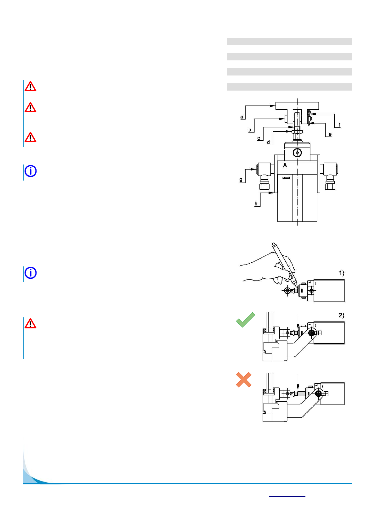
picture 7: locking