manuals.online logo
Brands
  1. Home
  2. •
  3. Brands
  4. •
  5. Graziadio & C.
  6. •
  7. Industrial Equipment
  8. •
  9. Graziadio & C. DV IS/ Series User manual

Graziadio & C. DV IS/ Series User manual

ISOLSBARRA
630 - 6300 A
Pag. 1 / 8
ISTR-ISOL-DV-05
ISTRUZIONI DI MONTAGGIO
ASSEMBLY INSTRUCTIONS
CASSETTE DI DERIVAZIONE
TAP OFF BOXES
VALIDO PER / VALID FOR:
DV**IS/*, DV**IS/*IP,
DV**IS/*M, DV**IS/*IPM,
DV*PDV
Via Pellice 75 –10098 Rivoli - Italy
Tel.+39.011.9591991 - e-mail info@graziadio.it
www.graziadio.it
ISOLSBARRA
630 - 6300 A
Pag. 2 / 8
ISTR-ISOL-DV-05
ATTENZIONE: EFFETTUARE LE SEGUENTI OPERAZIONI CON LINEA NON IN TENSIONE!
ATTENTION: DISCONNECT THE BUSBARS FROM THE ELECTRICAL CURRENT BEFORE
REALIZING THE FOLLOWING OPERATIONS!
1
Sulla linea montata rimuovere il
coprigiunto di plastica nera in
modo da scoprire la giunzione;
On the mounted line remove the
black plastic cover joint in order
to uncover the connection;
2
Rimuovere la vite superiore del
giunto esistente. Nel caso di
inserimento della cassetta nel
punto di derivazione non c’è da
rimuovere nessuna vite. Inserire la
rondella elastica e la nuova vite
M10x30 (non serrare);
Remove the upper screw of the
existing joint. If the tap off box is
inserted in the plug-in point, no
screws must be removed. Insert
the elastic washer and the new
screw M10x30 (do not tighten);
3
Prendere la cassetta e aprirla
con l’apposita chiave;
Take the box and open it with
the appropriate key;
4
Aprire il pacchetto presente
all’interno della cassetta e dividere
i pezzi da usare in seguito;
Open the package inside the box
and divide the pieces to use later;
ISOLSBARRA
630 - 6300 A
Pag. 3 / 8
ISTR-ISOL-DV-05
5
Inserire le bandelle
sull’Isolsbarra (vedi foto) nella
sequen
za
seguen
te:
Neutro
(se
present
e) - L1
- L2 -
L3 - L1
- L2 -
L3 e
serrare
le viti
10 x 30
(molle a tazza) della giunzione a
60 Nm per le bandelle in rame, a
40 Nm per quelle in alluminio;
Insert the bars into the
Isolsbarra (see photo) in the
following sequence:
Neutral (if present) - L1 - L2 - L3
- L1 - L2 - L3 and tighten the
junction screws 10 x 30 to 60
Nm for copper bars, to 40 Nm
for aluminium bars;
N°
con
d.
In
interrut
tori
In
switche
s
L
1
L
2
L
3
N
4
160
1
1
1
1
4
400
1
1
1
1
6
400
2
2
2
0
7
160
2
2
2
1
7
400
2
2
2
1
8
400
2
2
2
2
9
1250
3
3
3
0
10
1250
3
3
3
1
6
Chiudere il coprigiunto con i nuovi
coperchi forati in plastica nera
presenti all’interno della cassetta;
incastrarli tra loro.
Close the cover joint with the new
black plastic perforated covers
inside the box; fit together.
COPERCHIO FORATO
HOLED COVER JOINT
7
Ribaltare di 180° la cassetta;
Tilt the box 180 degrees;
ISOLSBARRA
630 - 6300 A
Pag. 4 / 8
ISTR-ISOL-DV-05
8
Montare le apposite staffe sul
fondo esterno della cassetta.
Inserire la cassetta (previa
asportazione della protezione
grigia con cacciavite, svitando),
controllare che la posizione del
neutro dell’interruttore
corrisponda con il neutro della
linea e fissare la cassetta tramite
le staffe avvitate alle piastrine;
N.
STAFFE/B
RACKETS
N.
DIM. CASSETTE/TAP
OFF BOXES
DIMENSIONS
4
600x300x200 mm
4
300x400x320 mm
6
1000x600x400 mm
8
1450x800x400 mm
Mount the special brackets on
the outer bottom of the tap off
box. Insert the tap off box (after
removing the grey protection),
check that the position of the
neutral of the switch corresponds
with the neutral of the line then
fix the tap off box with the
brackets by adjusting them with
the loops;
9
Smontare la protezione in
vetroresina (bianca o rossa);
Remove the fiberglass protection
(white or red);
ISOLSBARRA
630 - 6300 A
Pag. 5 / 8
ISTR-ISOL-DV-05
10
Montare i conduttori per il parallelo delle bandelle come da foto
utilizzando le viti 6MA e i dadi flangiati in dotazione assieme alle
bandelle viste precedentemente (in base al tipo di ISOLSBARRA DV
verranno forniti i conduttori a "C" o i conduttori a "L”). Iniziare dalla
più corta (fase L3 o T); ▪Linea con 1 conduttore per fase:
Mount the conductors for the paralleling of the bars as shown in the
picture using the 6MA screws and flange nuts supplied with the bars
seen above (depending on the type of ISOLSBARRA DV the "C" or "L"
conductors will be supplied). Start with the shortest one (phase L3 or
T);
•Linea con 1 conduttore per fase / Line with 1 conductor per
phase:
CONDUTTORI A “L”
“L” CONDUCTORS
•Linea con 2 conduttori per fase / Line with 2 conductors per
phase:
CONDUTTORI A “C” PER PARALLELO
“C” BARS FOR PARALLEL
•Linea con 3 conduttori per fase / Line with 3 conductors per
phase:
CONDUTTORI
A “L”
“L”
CONDUCTORS
CONDUTTORI A
“C” PER
PARALLELO
“C” BARS FOR
ISOLSBARRA
630 - 6300 A
Pag. 6 / 8
ISTR-ISOL-DV-05
13
Terminare l’assemblaggio fissando la lastra in vetroresina alla cassetta
con le viti fornite.
Finish the assembly with fixing the fiberglass cover sheet to the tap off
box with the supplied screws.
11
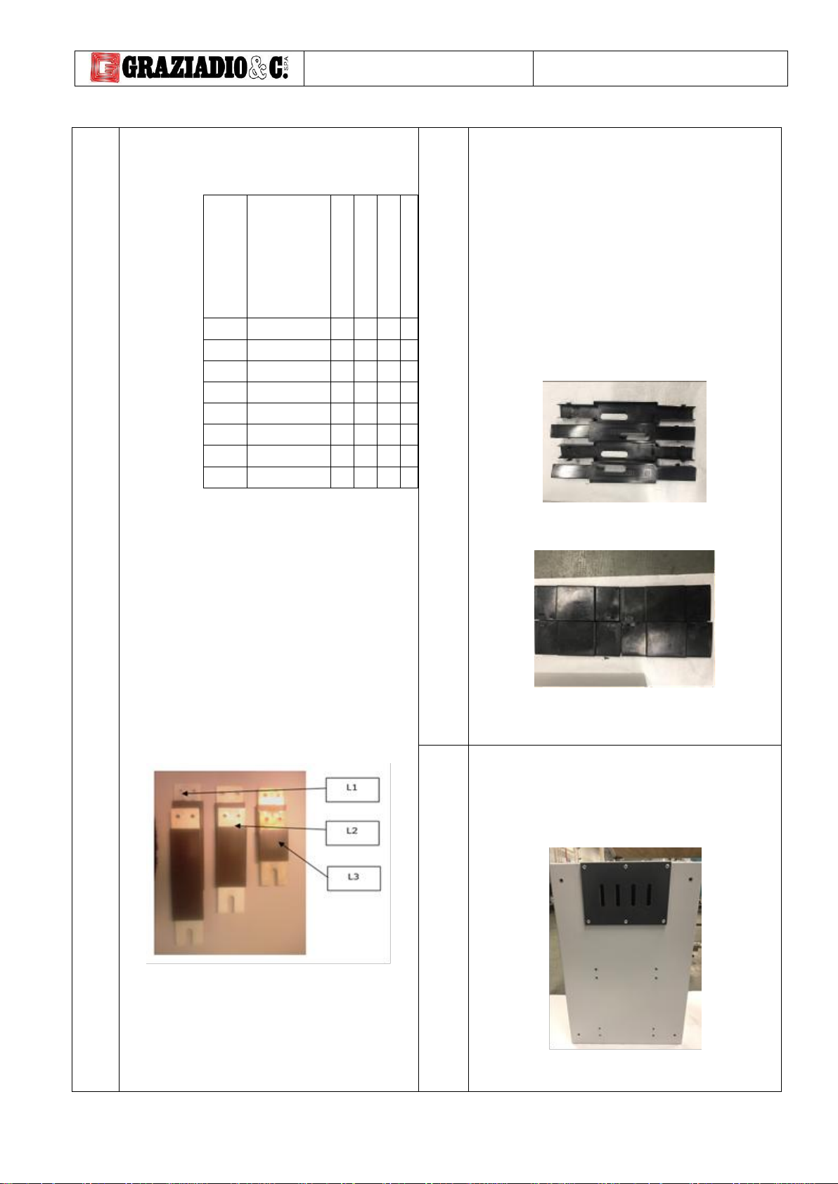
Collegare i conduttori (barra,
treccia o cavo) provenienti
dall’interruttore a quanto
realizzato. In base alla fase a cui
vanno collegate avranno una
diversa lunghezza (Valido solo se
l’interruttore è fornito da
Graziadio). In seguito, fissare la
barra con le relative viti, rondelle
elastiche e dadi (un’estremità
collegata all’interruttore, l’altra
ai conduttori tipo "C" o "L");
Connect the conductors (bar,
braid or cable) coming from the
switch to what has been made.
Depending on the phase to
which they are to be connected,
they will have a different length
(valid only if the switch is
supplied by Graziadio). Then fix
the bar with the relative screws,
elastic washers and nuts (one
end connected to the switch, the
other to the "C" or "L" type
conductors);
12
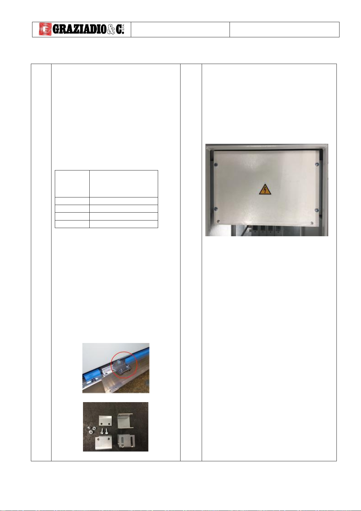
Collegare il cavo di terra alla vite
8MA posta all’inizio della cassetta
lato uscita cavi.
Connect the earth cable to the
screw 8MA located at the
beginning of the box on the cable
exit side.
ISOLSBARRA
630 - 6300 A
Pag. 7 / 8
ISTR-ISOL-DV-05
14
Per collegare i cavi forare il fondo della cassetta come necessario;
To connect the cables, drill the bottom of the box as necessary;
15
Chiudere la cassetta con l’apposita chiave.
Se montato un interruttore azionare la maniglia.
Close the box with the appropriate key.
If a switch is fitted, operate the handle.
ISOLSBARRA
630 - 6300 A
Pag. 8 / 8
ISTR-ISOL-DV-05
INDICAZIONI FINALI
FINAL INSTRUCTIONS
Prima di mettere in funzione la linea accertarsi di:
1) Aver correttamente serrato i bulloni come indicato;
2) Effettuare la prova di isolamento con almeno 2200 V.
La resistenza deve essere maggiore di 1000 Ω/V verso terra per ogni
circuito.
Before setting the line at work check that:
1. The bolts are correctly tightened;
2. Make the isolation test under 2200 V at least.
The resistance of each circuit towards earth must be higher than 1000
Ω/V.
Per ulteriori informazioni / For further information:
Tel.+39.011.9591991, e-mail [email protected]

This manual suits for next models

1

Other Graziadio & C. Industrial Equipment manuals

Graziadio & C. GDA401600 User manual

Graziadio & C.

Graziadio & C. GDA401600 User manual

Graziadio & C. K Series User manual

Graziadio & C.

Graziadio & C. K Series User manual

Graziadio & C. K Series User manual

Graziadio & C.

Graziadio & C. K Series User manual

Popular Industrial Equipment manuals by other brands

Mitek RoofTracker II Service bulletin

Mitek

Mitek RoofTracker II Service bulletin

SUHNER MACHINING MAX 40 instruction manual

SUHNER MACHINING

SUHNER MACHINING MAX 40 instruction manual

Schmalz X-Pump SXP Brief operating instructions

Schmalz

Schmalz X-Pump SXP Brief operating instructions

Atlanta BWL 108e Document procedure

Atlanta

Atlanta BWL 108e Document procedure

Nexen AIR CHAMP FMCBE 110-14 user manual

Nexen

Nexen AIR CHAMP FMCBE 110-14 user manual

Sic Marking i143 user manual

Sic Marking

Sic Marking i143 user manual

ROBEL 22.38/02 operating instructions

ROBEL

ROBEL 22.38/02 operating instructions

ABB A145-M65 Operation manual

ABB

ABB A145-M65 Operation manual

Big Daishowa BBT30 Operation manual

Big Daishowa

Big Daishowa BBT30 Operation manual

KGK EX 15L Use and maintenance manual

KGK

KGK EX 15L Use and maintenance manual

ABB TRS 61D01 Operation manual

ABB

ABB TRS 61D01 Operation manual

ABB HT845182 Operation manual

ABB

ABB HT845182 Operation manual

HEIDENHAIN ND 1400 QUADRA-CHEK -  GUIDE operating instructions

HEIDENHAIN

HEIDENHAIN ND 1400 QUADRA-CHEK - GUIDE operating instructions

KAKA Industrial TB-12 Operation manual

KAKA Industrial

KAKA Industrial TB-12 Operation manual

ABB HT612032 Operation manual

ABB

ABB HT612032 Operation manual

Finn 5 Series Operator Instructions And Parts Manual

Finn

Finn 5 Series Operator Instructions And Parts Manual

QS Quick-Slide Mountinganchor Assembly instructions

QS

QS Quick-Slide Mountinganchor Assembly instructions

Balluff BTL5-A/C/E1-MSF-F Series Condensed guide

Balluff

Balluff BTL5-A/C/E1-MSF-F Series Condensed guide

manuals.online logo
manuals.online logoBrands
  • About & Mission
  • Contact us
  • Privacy Policy
  • Terms and Conditions

Copyright 2025 Manuals.Online. All Rights Reserved.