10
Water supply for manual spray bar:
A wash-water supply is required for connection to the valve, rated: 1/2 inch BSP, 0.75 l/
sec (0.2 USG/sec) @ 3-6 bar. Temp 40-60 C (104 -140 F) Note that the same spray bar
is used also for automatic wash system.
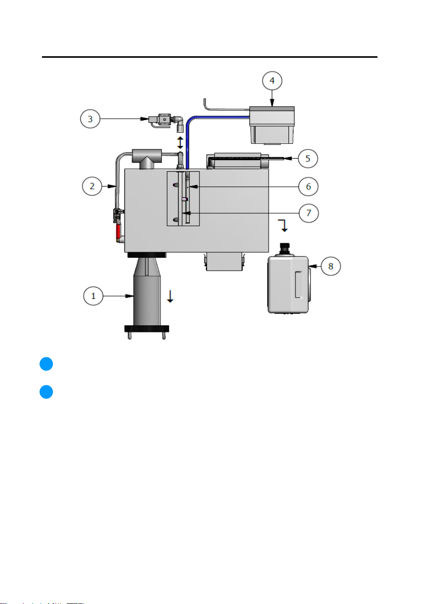
Automatic wash valve assembly. (Assembly Diagram on page 23)
Attention! See point 2 above on local regulations that may apply before installation.
The automatic wash valve is supplied as standard on combi oven models X7C and
X15C (instead of the manual valve and hose assembly). For all other models: X15, X20,
X25, X35 this system is only available as an upgrade at time of order. Wash water
supply required:1/2 inch BSP, 0.75 l/ sec (0.2 USG/sec) @ 3-6 bar. Temp 40-60 C (104 -
140 F) The solenoid power cable is routed to Grease Guardian controller, and is pre-
fitted at factory.
Air blower Assembly. Non standard Item. Upgrade for models X15 to 35. Supplied
with a wall mount bracket. Blower must be wall mounted above lid level of Grease
Guardian unit. This system is supplied with air hose and push fit attachment for connec-
tion to air bar (item 8). The power cord plug must be plugged to a wall electrical outlet
separate to the Grease Guardian supply. Instructions for setting the blower timer are
provided separately with the upgrade kit.
Mains Power Cord for Grease Guardian system. Supplied with electrical plug attach-
ment. The cord is supplied already routed to Grease Guardian controller through the
rear of the machine. The Grease Guardian System should only be powered up after
filling tank with water ensuring water level reaches internal skimming drum.
Blower Air Bar. Supplied only if a blower system is included. Comprised of a two piece
“L “shaped steel bar. The lower section is submerged inside tank. This section is to be
screwed into the upper section which is mounted at side of tank and includes a push fit
connection for connection to air blower hose.
Spray bar for manual or automatic spraying system (See Note 2). The spraybar is
supplied with spray nozzles in place. Ensure the nozzles are directed diagonally down
towards the water surface below in an inverted “V” position
Grease Guardian oil container. Ensure there is adequate clearance to access and
remove the container as shown. Refer to specification sheet if required.
3
4
5
6
7
8
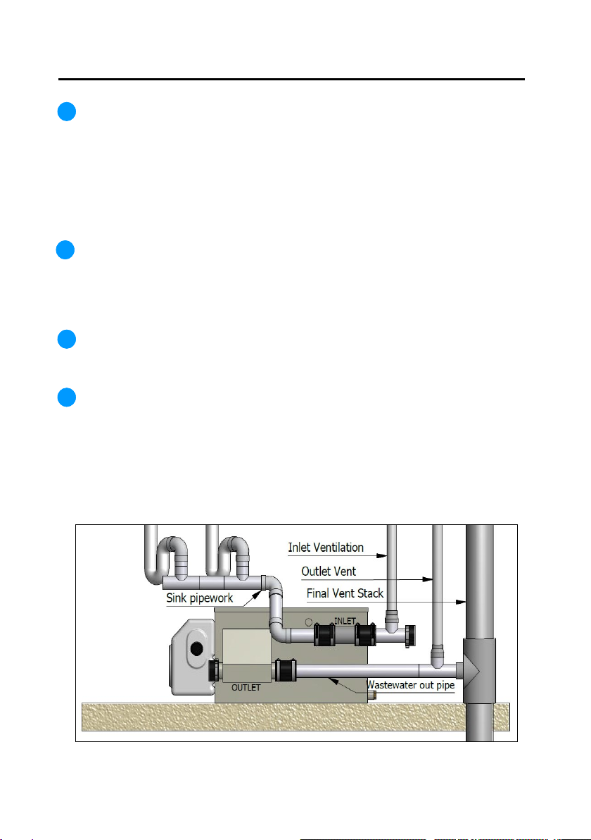
Plumbing and Mechanical Installation