Great Dane Champion CP User manual

Please route to the individual
responsible for trailer maintenance
Part No. 42101401
maintenance manual
for van and platform trailers
maintenance manual
drive away with more

VANS
Reporting Safety Defects . . . . . . . . . . . . . . . . . . . . 2
Reporting Other Claims. . . . . . . . . . . . . . . . . . . . . . 2
Introduction . . . . . . . . . . . . . . . . . . . . . . . . . . . . . . . 3
Maintenance Tips . . . . . . . . . . . . . . . . . . . . . . . . . . 4
Appearance Maintenance . . . . . . . . . . . . . . . . . . . . 5
Freezing Weather Maintenance. . . . . . . . . . . . . . . . 5
Suggested Preventive Maintenance . . . . . . . . . . . . 5
Electrical System. . . . . . . . . . . . . . . . . . . . . . . . . . . 6
Brake Maintenance . . . . . . . . . . . . . . . . . . . . . . . . . 7
Brake Care and Adjustment . . . . . . . . . . . . . . . . . . 8
Brake Adjusters . . . . . . . . . . . . . . . . . . . . . . . . . . . . 9
Parking Brakes . . . . . . . . . . . . . . . . . . . . . . . . . . . 10
Brake Balance . . . . . . . . . . . . . . . . . . . . . . . . . . . . 10
Oil Seals and Hub Caps . . . . . . . . . . . . . . . . . . . . 11
Wheel Bearings . . . . . . . . . . . . . . . . . . . . . . . . . . . 11
Suspensions . . . . . . . . . . . . . . . . . . . . . . . . . . . . . 13
Running ear Assembly . . . . . . . . . . . . . . . . . . . . 14
Servicing Rims and Wheels. . . . . . . . . . . . . . . . . . 14
Single-Piece Rim Wheels . . . . . . . . . . . . . . . . . . . 15
Rim and Wheel Inspection and Maintenance . . . . 15
Rim and Wheel Problems . . . . . . . . . . . . . . . . . . . 16
Tire Care . . . . . . . . . . . . . . . . . . . . . . . . . . . . . . . . 17
Axle Alignment. . . . . . . . . . . . . . . . . . . . . . . . . . . . 19
Upper Coupler and Kingpin . . . . . . . . . . . . . . . . . 20
Pintle Hook . . . . . . . . . . . . . . . . . . . . . . . . . . . . . . 21
Support ear. . . . . . . . . . . . . . . . . . . . . . . . . . . . . 21
Rear Impact uard . . . . . . . . . . . . . . . . . . . . . . . . 21
Side and Roof Panels - Vans . . . . . . . . . . . . . . . . 22
Rear Frame, Doors and Hardware . . . . . . . . . . . . 22
Entry and Exit . . . . . . . . . . . . . . . . . . . . . . . . . . . . 23
Floor System . . . . . . . . . . . . . . . . . . . . . . . . . . . . . 23
Insulated Trailer Maintenance . . . . . . . . . . . . . . . . 23
Maintaining Insulation Efficiency. . . . . . . . . . . . . . 24
Safety Measures - Urethane Foam . . . . . . . . . . . . 24
Converter Dolly . . . . . . . . . . . . . . . . . . . . . . . . . . . 25
Alterations to the Trailer . . . . . . . . . . . . . . . . . . . . 26
P ATFORMS
Reporting Safety Defects . . . . . . . . . . . . . . . . . . . . 2
Reporting Other Claims. . . . . . . . . . . . . . . . . . . . . . 2
Introduction . . . . . . . . . . . . . . . . . . . . . . . . . . . . . . . 3
Maintenance Tips . . . . . . . . . . . . . . . . . . . . . . . . . . 4
Appearance Maintenance . . . . . . . . . . . . . . . . . . . . 5
Freezing Weather Maintenance. . . . . . . . . . . . . . . . 5
Suggested Preventive Maintenance . . . . . . . . . . . . 5
Electrical System. . . . . . . . . . . . . . . . . . . . . . . . . . . 6
Brake Maintenance . . . . . . . . . . . . . . . . . . . . . . . . . 7
Brake Care and Adjustment . . . . . . . . . . . . . . . . . . 8
Brake Adjusters . . . . . . . . . . . . . . . . . . . . . . . . . . . . 9
Parking Brakes . . . . . . . . . . . . . . . . . . . . . . . . . . . 10
Brake Balance . . . . . . . . . . . . . . . . . . . . . . . . . . . . 10
Oil Seals and Hub Caps . . . . . . . . . . . . . . . . . . . . 11
Wheel Bearings . . . . . . . . . . . . . . . . . . . . . . . . . . . 11
Suspensions . . . . . . . . . . . . . . . . . . . . . . . . . . . . . 13
Running ear Assembly . . . . . . . . . . . . . . . . . . . . 14
Servicing Rims and Wheels. . . . . . . . . . . . . . . . . . 14
Single-Piece Rim Wheels . . . . . . . . . . . . . . . . . . . 15
Rim and Wheel Inspection and Maintenance . . . . 15
Rim and Wheel Problems . . . . . . . . . . . . . . . . . . . 16
Tire Care . . . . . . . . . . . . . . . . . . . . . . . . . . . . . . . . 17
Axle Alignment. . . . . . . . . . . . . . . . . . . . . . . . . . . . 19
Upper Coupler and Kingpin . . . . . . . . . . . . . . . . . 20
Pintle Hook . . . . . . . . . . . . . . . . . . . . . . . . . . . . . . 21
Support ear. . . . . . . . . . . . . . . . . . . . . . . . . . . . . 21
Rear Impact uard . . . . . . . . . . . . . . . . . . . . . . . . 21
Floor System . . . . . . . . . . . . . . . . . . . . . . . . . . . . . 23
Main Beams. . . . . . . . . . . . . . . . . . . . . . . . . . . . . . 25
Crossmembers . . . . . . . . . . . . . . . . . . . . . . . . . . . 25
Extendable Platforms . . . . . . . . . . . . . . . . . . . . . . 25
Converter Dolly . . . . . . . . . . . . . . . . . . . . . . . . . . . 25
Running ear Assembly . . . . . . . . . . . . . . . . . . . . 26
Alterations to the Trailer . . . . . . . . . . . . . . . . . . . . 26
AdvantED E . . . . . . . . . . . . . . . . . . . . . . . . . . . . . 27
Bibliography. . . . . . . . . . . . . . . . . . . . . . . . . . . . . . . . . . . . . . . . . . . . . . . . . . . . . . . . . . . . . . . . . . . . . . . . . . . . . . . 28
Appendix . . . . . . . . . . . . . . . . . . . . . . . . . . . . . . . . . . . . . . . . . . . . . . . . . . . . . . . . . . . . . . . . . . . . . . . . . . . . . . . . . 29
maintenance man al

This vehicle was designed and quality inspected to con-
form with all applicable National Highway Traffic Safety
Administration (NHTSA) safety standards.
reat Dane Limited Partnership warrants this vehicle to
be free from defects in materials and workmanship in
accordance with its standard printed warranty
(see Appendix). If you detect a defect that could cause
an accident, injury or death; or if you wish to report any
such accident, injury or death, or any property
damage claim or other complaint not addressed to
the Customer Service Department, then you should
in writing advise:
Director, Customer Service
Great Dane Limited Partnership
P.O. Box 67
Savannah, GA 31402-0067
If you believe that your vehicle has a defect which could
cause a crash or could cause injury or death, you
should immediately inform NHTSA in addition to
notifying reat Dane Limited Partnership.
If NHTSA receives similar complaints, it may open an
investigation, and if it finds that a safety defect exists in
a group of vehicles, it may order a recall and remedy
campaign. However, NHTSA cannot become involved in
individual problems between you, your dealer, or reat
Dane Limited Partnership.
To contact NHTSA, you may call the Vehicle Safety
Hotline toll-free at 1-888-327-4236 (TTY: 1-800-424-
9153); go to http://www.safercar.gov; or write to:
Administrator, NHTSA,
1200 New Jersey Avenue, SE West Building
Washington, DC 20590.
You can also obtain other information about motor
vehicle safety from http://www.safercar.gov.
Customer Service Phone Number: 877-369-3493
The Great Dane O erator’s Manual, included with
every new trailer, will give specific information about
the following subjects:
Gross Axle Weight Rating (GAWR)
Gross Vehicle Weight Rating (GVWR)
Cargo Capacity
Proper Loading & Weight Distribution
Information shown in this Maintenance Manual is
general information for maintenance and preventive
maintenance of your reat Dane trailer. It is strongly
recommended that you obtain specific maintenance
instructions provided by the manufacturers of the
components specified on this trailer. Refer to the
bibliography in the back of this manual.
t is recommended that all necessary replacement components be from the original equipment
manufacturers to insure proper fit and to maintain the structural capability built into your vehicle.
2 3
reporting safety defects
and other claims
warning
This safety alert symbol is used throughout this manual to indicate potential
personal safety hazards. Failure to heed the warnings associated with the
safety alert symbol can result in property damage, serious injury or death.
safety preca tions
Before performing any maintenance or repair
work which requires raising the vehicle, ensure
vehicle is properly supported with lift stands of
sufficient rating capacity. Do not rely on jacks
alone for support of the vehicle.
Safety glasses and hard hats should be worn
when repairing and maintaining this vehicle.
A serious or fatal injury can occur...
A. If you lack proper training.
B. If you fail to follow proper safe procedures.
C. If you do not use proper tools and
safety equipment.
D. If you fail to use compatible replacement
components.
notice
This manual has been prepared to assist you in retain-
ing the safety, dependability, and performance that are
built into reat Dane trailers. It is essential that this trail-
er receives periodic inspections, maintenance, and
service parts replacement.
Maintenance should be performed by reat Dane
branches and dealers, or other qualified service outlets
that regularly provide such service. The reat Dane
Operator’s Manual covers pre-trip inspections, safety
and maintenance checks, and other helpful information
regarding reat Dane trailers. If you have questions
about this manual or its instructions, contact reat
Dane Trailers Customer Service Department for
answers.
It is important that every trailer owner and/or operator
have an organized Trailer Preventive Maintenance (TPM)
program. The United States Department of Transportation
requires that the maintenance records be kept on every
commercial highway vehicle.
It is to your advantage to be able to show that regularly
scheduled TPM inspection checks have been made on
every piece of equipment operated. A regular TPM
program will assure that you get the most from your
reat Dane trailer.
introd ction

BREAKING-IN A NEW TRAI ER
The most critical time in a new trailer’s life is its initial
in-service check and first month’s “shakedown.”
Preventive maintenance mechanics should be alert for
under-inflated tires and threaded fasteners that may
have loosened from factory-torque settings. Fastener
torque should be all-inclusive and include refrigeration
units, tanks, steps, carriers etc.
Following are several areas that deserve particularly
close attention during the first 30 days of a van or
platform trailer’s service life. Of course, your
operation’s maintenance records should reflect all areas
which need to be closely checked.
TIRES
While a new trailer’s tires were correctly inflated when
they were mounted at the factory, tire pressure is
related to ambient temperature at inflation time. If a new
trailer had tires mounted in a 70˚ F. ambient
environment, but was put in service in 20˚ F. weather,
the tires may have lost as much as 10 psi for every drop
of 20˚ F. in ambient temperatures below 50˚ F. Therefore,
all tire pressures should be verified with an air gauge,
and rechecked each time the tractor refuels.
WHEE S
Smaller fleets commonly overlook the need to retighten
new-trailer-wheel lug nuts after the first 50 to 100 mi. of
service on the initial “in-service.” Retightening
compensates for “normal” clamp force lost due to
“seating in” of new materials. Tests have shown
new-trailer-wheel lug nuts lose 250 lb-ft, or about half of
their original torque value, during a short period of initial
service. Unless those nuts are retightened to spec,
additional clamping force will be lost, and
damage to components will occur. Re-tightening during
the initial in-service prevents wheel and stud damage.
Thereafter, lug nuts should be checked every 25,000 mi.
EAF-SPRING SUSPENSIONS
All tandem axles are aligned when new trailers leave the
factory. However, suspension fasteners may sometimes
loosen, possibly causing alignment settings to change,
and that can translate into possible erratic ride, or
accelerated tire wear. Therefore, at the first TPM
interval, all suspension-system fasteners should be
rechecked for correct torque value.
When tightening suspension-system fasteners,
mechanics must tighten the “nut side” of torque-arm
bolts. Tightening bolt heads does not produce the
correct clamping force on the fastener.
It is also important to keep U-bolts, as well as torque-
arm bolts, tight. Loose U-bolts allow trailer axles to
shift, and even minor shifting during braking can cause
control problems, excessive tire wear, or even broken
spring leaves.
When U-bolts are torqued to proper specs, leaf-spring
main leaves remain in proper contact with wear pads,
with no “twists.” Spring wear-pad contact will then be
even, too.
Also, at the first TPM, a trailer mechanic should take the
time to verify that there are no obstructions to move-
ment of the suspension equalizers.
When the mechanic has made sure all fasteners are
tight, he should use the 50-ft.-tape method, with axle
extenders, to verify that the trailer tandem is, indeed,
properly aligned. Remember: the longer the trailer,
the more critical tandem alignment is to long tire life.
AIR-SPRING SUSPENSIONS
Loose U-bolts in an air-spring suspension can cause a
new trailer to roll and sway. Usually, a driver is quick
to report this condition. The mechanic should make
doubly sure that trailer-suspension fasteners, including
U-bolts, are properly tightened.
Excessive play in an air-spring suspension’s front-pivot
connection is another cause of premature tire wear and
erratic handing. Again, connection bolts, which may
have loosened during the first weeks of service, may
produce such handling problems. If not retightened,
these loose bolts can cause rubber bushing wear.
S IDING-TANDEM OPERATION
A driver learning to handle a new trailer equipped with a
sliding tandem should be sure he knows exactly how to
use the stop-selector bar. He should also make sure
that all four slider lock pins are set in place before
operating the trailer, otherwise the tandem may not be
“locked,” and a sudden brake application could force
the slider rearward, causing damage to the tandem
and trailer.
AIR SYSTEM AND BRAKE OPERATION
During the first month’s operation, a certain amount
of “burnishing in” of brake lining occurs. This is normal
and may result in some adjustment loss. Because
out-of-adjustment trailer brakes mean increased stop-
ping distance, plus an increased potential for jackknif-
ing under certain conditions, trailer brake adjustment
should be checked at the first TPM inspection.
During routine maintenance the dust cover cap on air
chambers must be inspected to assure that is in place
and sealing properly.
ANNUA FHWA INSPECTION
It is the carriers’ responsibility to make sure that the
vehicles operated by them are inspected and main-
tained under this Federal requirement. During this
inspection, make sure the upper slide rail to crossmem-
ber welds, pintle hook assemblies, safety equipment,
etc. are inspected and corrected as required.
DOORS
Almost invariably, a new trailer’s hinged-type doors
are difficult to latch. Drivers should expect to use extra
muscle to secure doors until seals seat, but drivers
should not use bars or some other device to force
doors shut. It is equally important not to make adjust-
ments to a new trailer’s door latches or hinges to
“correct” door closing. This will result in a poor sealing
later on.
Appearance maintenance includes cleaning, polishing,
corrosion prevention and removal, and protective
coatings. You must have a working knowledge of each
for the complete and proper appearance maintenance
of a reat Dane trailer.
WASHING AND CHEMICA S
Improper use of chemical cleaners has caused many
a newly delivered trailer’s finish to streak and fade,
particularly yellow, red and black models. Ironically,
fade is often caused by a desire to keep the units
clean—and using too strong a chemical solution. When
instructions call for a 150:1 water/chemical ratio, do not
use a 50:1 ratio. Sometimes fading caused by an overly
concentrated caustic agent may be remedied with
warm water rinsing and application of a glazing wax.
APPEARANCE MAINTENANCE MATERIA S
Many chemical companies compound materials for
appearance maintenance, and most provide instructions.
Protective films, such as paints and clear coats, are
necessary for the prevention of corrosion and the
preservation of metal and wood surfaces. They add
color, beauty, and distinction.
Trailer undercoat materials can lose effectiveness if
steam cleaned or if they come in contact with most
solvents.
The underside, including beams, has been undercoated
with a special, soft, rust preventive coating. To prolong
the life of this coating, avoid the use of high-pressure
washers, strong cleaning solutions and brighteners.
Due to the normal weathering and abrasion caused
by road conditions this coating must be inspected and
recoated as necessary (approximately every 24 months).
Dry-freight laminated wood floors should be cleaned
by sweeping and should not be washed out.
BENEFITS OF APPEARANCE MAINTENANCE
Complete and proper appearance maintenance of
reat Dane trailers not only adds to their physical
condition and ultimate trade-in value but also favorably
affects the operator’s feelings about himself and his
company. It also favorably affects the public image
of the company.
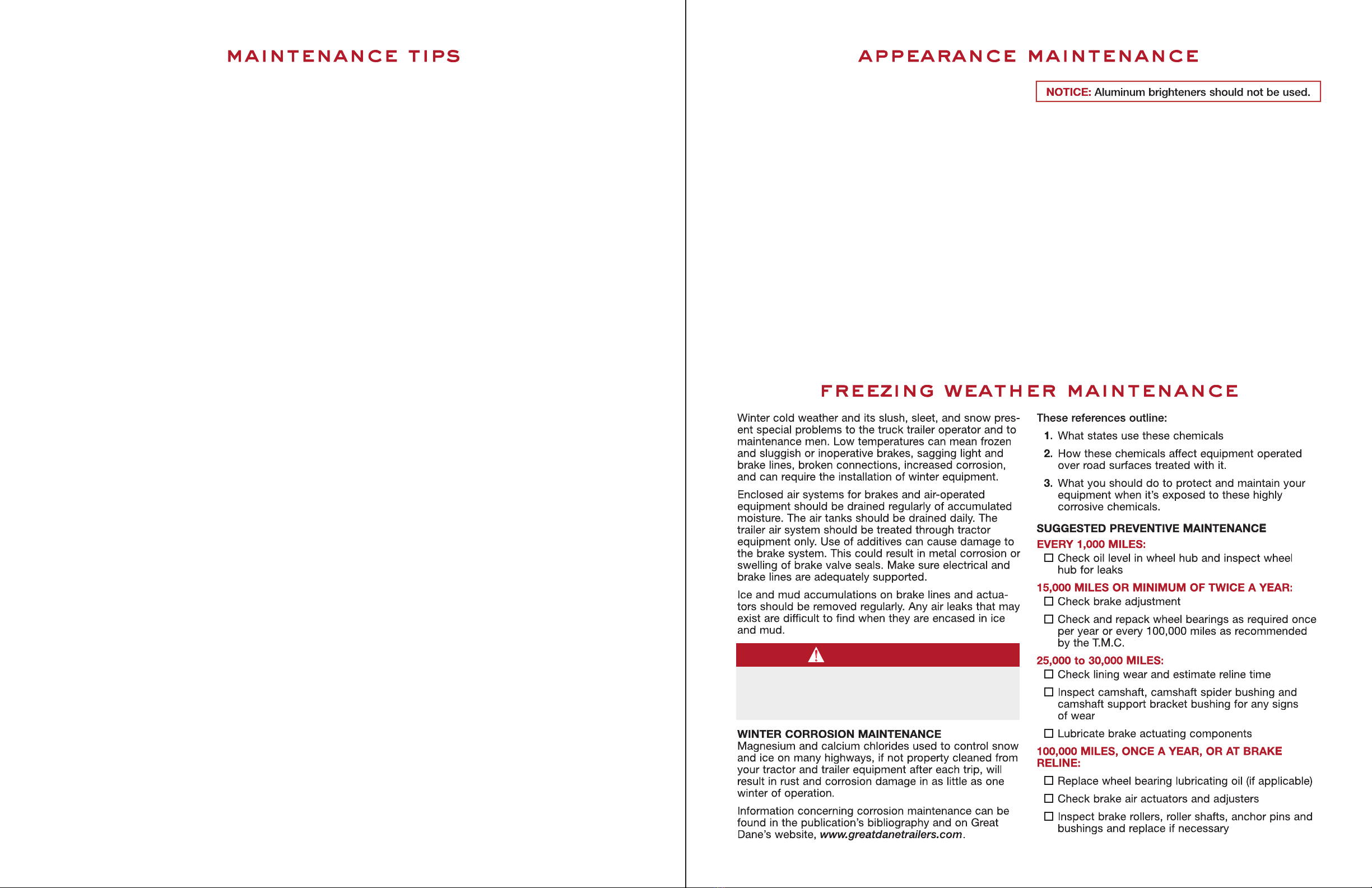
Winter cold weather and its slush, sleet, and snow pres-
ent special problems to the truck trailer operator and to
maintenance men. Low temperatures can mean frozen
and sluggish or inoperative brakes, sagging light and
brake lines, broken connections, increased corrosion,
and can require the installation of winter equipment.
Enclosed air systems for brakes and air-operated
equipment should be drained regularly of accumulated
moisture. The air tanks should be drained daily. The
trailer air system should be treated through tractor
equipment only. Use of additives can cause damage to
the brake system. This could result in metal corrosion or
swelling of brake valve seals. Make sure electrical and
brake lines are adequately supported.
Ice and mud accumulations on brake lines and actua-
tors should be removed regularly. Any air leaks that may
exist are difficult to find when they are encased in ice
and mud.
WINTER CORROSION MAINTENANCE
Magnesium and calcium chlorides used to control snow
and ice on many highways, if not property cleaned from
your tractor and trailer equipment after each trip, will
result in rust and corrosion damage in as little as one
winter of operation.
Information concerning corrosion maintenance can be
found in the publication’s bibliography and on reat
Dane’s website, www.greatdanetrailers.com.
These references outline:
1. What states use these chemicals
2. How these chemicals affect equipment operated
over road surfaces treated with it.
3. What you should do to protect and maintain your
equipment when it’s exposed to these highly
corrosive chemicals.
SUGGESTED PREVENTIVE MAINTENANCE
EVERY 1,000 MI ES:
Check oil level in wheel hub and inspect wheel
hub for leaks
15,000 MI ES OR MINIMUM OF TWICE A YEAR:
Check brake adjustment
Check and repack wheel bearings as required once
per year or every 100,000 miles as recommended
by the T.M.C.
25,000 to 30,000 MI ES:
Check lining wear and estimate reline time
Inspect camshaft, camshaft spider bushing and
camshaft support bracket bushing for any signs
of wear
Lubricate brake actuating components
100,000 MI ES, ONCE A YEAR, OR AT BRAKE
RE INE:
Replace wheel bearing lubricating oil (if applicable)
Check brake air actuators and adjusters
Inspect brake rollers, roller shafts, anchor pins and
bushings and replace if necessary
NOTICE: Aluminum brighteners should not be used.
4 5
maintenance tips appearance maintenance
freezing weather maintenance
warning
Do not use heat on any part of the air system.
The use of heat can cause a rupture and can be
very dangerous.

A warning decal, as shown on the previous page, is
located on the front of each trailer. You may trace
individual electrical circuits by the wire colors indicated.
Refer to the schematic drawing and the decal for
conductor numbers and wire colors.
Use only a 12-volt DC battery for checking lamps or
antilock brake systems. Never use battery chargers or
transformers.
Inspect all wiring to see that it is not damaged, and
that it is properly supported and protected, with all
connections tight. Frayed or damaged wiring should be
replaced with stranded cable of equal size or larger, and
should never be replaced with a smaller cable, or with a
solid conductor. All holes where wiring passes through
must contain rubber grommets.
Never replace fuses or breakers with metal foil or other
devices.
DISC BRAKE SCHEDU ED MAINTENANCE
Several different brands of disc brakes are available
in the market lace. Because rocedures differ brand
to brand, refer to the maintenance and adjustment
information from the manufacturer of the s ecific
brake in question.
DRUM BRAKE SCHEDU ED MAINTENANCE
Establish a preventive maintenance schedule for
the periodic adjustment, cleaning, inspection, and
lubrication of brake equipment on the basis of past
experience and expected severity of operations. Take
into account that linings and drums are particularly
subject to wear and should not be allowed to wear
to the point where rivets or bolts may contact brake
drums. To compensate for this, schedule brake
inspections as frequently as required to maintain
satisfactory operation and maximum safety (not to
exceed 25,000 miles). Accepted maintenance practices
require that bearings should be adjusted properly
before making brake adjustments; that adjustments
provide uniform lining clearance, correct travel of levers,
and proper equalization; and that brakes should be
cleaned, inspected, lubricated, and adjusted each time
the hubs are removed.
MAINTENANCE DURING MAJOR OVERHAU
OF BRAKES
During a major overhaul, check the following parts and
replace them with original equipment parts or equal, as
required:
1. Spiders – for looseness or sheared fasteners.
2. Anchor pins – for wear or misalignment.
3. Brake shoes – for wear at anchor pin holes.
4. Cam shafts and cam shaft bearings or bushings –
for wear.
5. Shoe-return springs – replace during overhaul and
when you replace lining. Do not reuse springs.
6. Brake linings – for oil or grease saturation, wear,
loose rivets or bolts.
7. Drums – for cracks, scoring, other damage.
Install all new lock rings where they are used.
During a major overhaul, before reassembling parts that
have been inspected, lightly coat cam shaft bushings
and cam roller follower shafts and journals with brake
lubricant.
For all fittings on cam shafts, meter-type fittings that
have a maximum of 40 psi pressure relief or shutoff are
recommended.
BRAKE UBRICANTS
A high-temperature waterproof grease in a number 1
NL I grade to lubricate the brake actuating system is
recommended. It should be smooth textured, corrosion
resistant, and free of fillers and abrasives. It should
maintain a satisfactory softness under normal parking
and storage temperatures so the brakes can be applied
and released.
The following greases meet these recommendations:
Texaco Thermotex EP #1 Shell Darina #1
Marathon 528 HD Sunaplex #1 EP
Amdex #1 EP Philube B #1
Trailers operating in extremely cold weather
(below -40˚ F) may require a grease conforming to
MIL- -25013C.
7
The electrical system on every reat Dane trailer meets
or exceeds all federal and state requirements in effect
at the time of manufacture. Wherever required by law,
lamps and reflectors are marked by the manufacturer to
indicate the appropriate specification with which each
complies.
For optimum performance and long life from the trailer’s
lamps and wiring, follow this inspection procedure.
Clean all reflective tape or devices and lamps. See that
all lamps burn properly. Replace all burned-out lamps
and broken or missing reflective devices. Factory-
approved replacement parts should be used, and
replacement bulbs or lamps of equal candlepower
should be used for safety.
NOTE: Electrical circuits may be protected by circuit
breakers located inside the front nose box.
6
GREEN
BROWN
WHITE
YELLOW
BROWN
WHITE
WHITE
WHITE-GREEN
BROWN
BROWN
GREEN
BROWN
WHITE
RED
BROWN
WHITE
BROWN
RED
RED
BROWN
WHITE
YELLOW
BROWN
WHITE
7 COND MAIN HARNESS
4 COND ABS HARNESS
— TOP VIEW OF TRAILER —FRONT REAR
BLUE
WHITE
WHITE-GREEN
RED
electrical system
brake maintenance
WIRING DIAGRAM
warning
Do not exceed 21 candlepower bulbs for dome
lamps. Stronger bulbs may generate excessive
heat and start a cargo fire. Cargo must be kept
away from dome lamps. Dome lamps must be
turned off for over-the-road operation.
ca tion
CONNECTOR WIRING CHANGE
NOTICE TO A TRACTOR-TRAI ER
OWNERS AND USERS
Federal Motor Vehicle Safety Standard No. 121,
Air Brake Systems, was amended by the National
Highway Traffic Safety Administration of DOT to
require that truck tractors manufactured on or
after March 1, 1997, provide constant power for
a trailer’s antilock brake system (ABS). Some
manufacturers provided this feature before the
effective date.
These tractors using a single 7-way electrical
connector will have constant power for ABS
on the center pin when the key switch is on.
Tractor-trailer owners and users who presently
use the center pin for auxiliary power to equip-
ment other than trailer ABS (for example, dome
lights, backing lights, bottom dumps, sliding
undercarriages, air ride dump valves, etc.) will
be affected by this change.
In certain uses of this constantly powered
center pin connector, unexpected or unintended
activation of this equipment may be hazardous
or result in personal injury.
BEFORE connecting your trailer to a tractor,
MAKE SURE that the constantly powered center
pin WI NOT UNINTENTIONA Y TURN ON
TRAI ER EQUIPMENT. If you have any questions
about your present wiring, or how to rewire your
vehicles, you should contact the tractor
manufacturer, auxiliary equipment manufacturer,
and/or reat Dane Trailers Customer Service
Department.
NOTICE: Most trailers are equipped with a sealed
wiring harness. Check the circuits at the plugs only
– do not cut or probe test for shorts. Every time
the harness is unplugged, repack connector with
rafo 112X grease or equivalent.
warning
Brake liners contaminated with lubricant cannot
be salvaged or cleaned. They must be replaced.
warning
TRA LER S EQU PPED W TH ANT LOCK BRAKE SYSTEM (ABS).
NO. 7 (BLUE) C RCU T S RESERVED FOR CONT NUOUS POWER
SUPPLY TO ABS. FOR MOST EFFECT VE ABS OPERAT ON,
TOW NG VEH CLE MUST SUPPLY M N MUM OF 10 AMPS AT
12.5 VOLTS TO NO. 4 (RED) & NO. 7 (BLUE) C RCU TS.
PIN CO OR CIRCUIT
1 WH TE GROUND RETURN TO TOW NG VEH CLE
2 BLACK CLEARANCE, S DE MARKER & D LAMPS
3 YELLOW LEFT TURN S GNAL & HAZARD LAMPS
4 RED STOP LAMPS & ABS POWER
5 GREEN R GHT TURN S GNAL & HAZARD LAMPS
6 BROWN TA L, L CENSE, CLEARANCE &
S DE MARKER LAMPS
7 BLUE ABS CONT NUOUS SHARED POWER
J560
SOCKET
FA LURE TO HEED
TH S WARN NG CAN RESULT
N PROPERTY DAMAGE,
SER OUS NJURY OR DEATH.

The trailer brake system will perform safely and
efficiently only as long as it is properly maintained
and not abused. Trailer brakes should be inspected
frequently in connection with a Trailer Preventive
Maintenance (TPM) Program. Out-of-adjustment brakes
can cause increased stopping distance, shorter brake
component life, and a greater tendency for the trailer
to jackknife.
AIR SYSTEM AND BRAKE OPERATION
Proper operation of the brake systems requires a
firm seal between the air brake couplers. Inspect the
couplers for seal damage and cracked housings. Some
couplers are equipped with filters. These filters must be
cleaned at regular intervals to prevent malfunction of
the brake systems. Inspect the air hoses for cracking
and for frayed connections. Be sure air hoses are not
rubbing on any metal surface or each other. Replace or
repair damaged components.
Keep the air system clean. All air tanks should be drained
daily to remove moisture and other contaminants. See
Freezing Weather Maintenance.
Some air valve manufacturers discourage the use of air
line antifreeze. Use may result in deterioration of seals
in these valves.
If you use Teflon tape or other thread sealers to seal
threaded connections in your air lines, be careful not
to allow pieces of the sealer to enter the air system.
It can clog passages into the valves and cause them
to malfunction.
Keep the air system tight. The air system cannot be
charged properly if there are leaks in reservoirs, lines,
hoses, or valves. Always check the tractor pressure
gauge for unusual drops or extended buildup times.
Run the tractor engine until the air brake system
pressure gauge shows at least 105 psi. Listen for air
leaks. With the engine off, check the gauge reading
with no brakes applied. The gauge reading loss should
not exceed three psi in one minute.
With the engine still off, apply the brakes fully for two
minutes. The gauge reading drop should not exceed
four psi in one minute.
With engine still off, slowly open drain cocks in the
trailer’s air tanks and allow the pressure to drop gradually.
In a system employing spring brake control valves, the
spring brakes should function and apply the brakes.
In a system that does not employ spring brake control
valves, the relay emergency valve should function and
apply the brakes.
A schedule for periodic cleaning, inspection, adjustment
and lubrication of brake equipment should be estab-
lished by the operator, based on past experience and
severity of operation.
BRAKE SHOES
Brake shoe designs vary, depending on the type of
brake and brake manufacturer. Some brakes require
special tools. If you have problems removing brake
shoes, refer to the brake manufacturer’s manual.
BRAKE SHOE SPRINGS
Replace weak or unmated brake shoe springs whenever
they cause pulling or dragging brakes. The springs are
constantly expanding and contracting in the confined
hot area of the brake drums. Excessive heat during
expansion will cause them to weaken.
BRAKE INERS
The certified ross Axle Weight Rating ( AWR) in many
cases is determined by the friction level of the brake
liners. The friction level is determined by the axle and
vehicle manufacturer to provide the required brake
torque as prescribed by governmental regulations.
REFACING DRUM
It is not a good practice to reface brake drums. Refacing
can weaken the drums, making them unable to dissipate
all the heat generated by brake applications, and making
them susceptible to distortion and heat cracks.
If brake drums must be refaced on cam-type brakes,
when oversized linings are used, precautions regarding
cam travel should be checked to prevent sticking cams
or cam rollover. This problem often exists when the
linings become worn. It may be necessary to install
oversized rollers to prevent this problem.
OVERSIZE INERS
To compensate for material removed when refacing
brake drums, X (1/16" oversize) and XX (1/8" oversize)
liners are furnished by the lining manufacturers. When
oversize liners are used the drums should be machined
in increments of 1/16" (radius increased 1/16").
BRAKE SHOE RO ER CAM FO OWERS
Roller cam followers are available in four sizes, each
having been designed for a specific purpose.
STANDARD SIZE (1.250")
Standard rollers are used when installing standard
lining with standard drums, X lining with 1/16" oversize
drums, or XX lining with 1/8" oversize drums.
If the drums have been refaced and oversize rollers later
installed, the oversize rollers must be removed and
standard rollers installed when the new liners are
installed.
1/8" OVERSIZE (1.375")
Use 1/8” oversize cam followers when you install
standard liners with worn or trued drums that are 1/32"
oversize. Circle grind the liners a few thousandths less
than the drum diameter.
1/4" OVERSIZE (1.500")
Use 1/4” oversize cam followers when X liners have
been installed with 1/16" oversize drums and standard
rollers. The standard rollers should be removed and
1/4" oversize installed before the lining becomes worn
to the point when the brake cam is no longer effective.
1/2" OVERSIZE (1.750")
Use 1/2” oversize cam followers when XX liners and
1/8" oversize drums have been used. The standard
rollers should be removed when the liners become
approximately 50% worn, and 1/2" oversize rollers
should be installed.
CAM P ATE SHIMS
When standard liners are installed with worn or trued
drums, or when X or XX liners have been installed and
are approximately 50% worn, shims or a combination of
shims should be installed under each of the cam wear
plates to permit the cam to be returned to the full
release position. Shims are available in 1/64", 1/32" and
1/16" thicknesses.
BRAKE DUST SHIE DS
The brake spiders used for mounting the brake shoe
assembly parts also become the mounting for optional
dust shields.
The use of dust shields should be determined by
conditions encountered by the trailer. Operations in
mud, sand, dirt, water, and other forms of foreign
materials should be the governing factors. When these
conditions exist during winter months and maximum
cooling is desirable during summer months, dust
shields are easily installed or removed.
AUTOMATIC ADJUSTERS
Several different brands of automatic adjusters are
common. Because adjustment differs, refer to the
maintenance and adjustment information from the
manufacturer.
Some automatic slacks are equipped with an adjust-
ment pawl which eliminates loss of adjustment. This
pawl must be removed prior to backing off on the
adjustment to prevent damage to the splined pawl
and adjusting screw.
8 9
brake care and adj stment
brake adj sters
warning
Serious air leaks in the trailer’s braking system
are hazardous conditions that require the trailer
to be placed out of service until they are
properly corrected.
warning
Enlarging the drum diameter may permit the
cam to rotate beyond its maximum lift when the
lining becomes worn. This can result in sticking
cams or cam rollover.
To avoid this condition and to obtain maximum
lining wear, oversize roller cam followers or
wear plate shims (depending on the brake
design) should be installed when the liners
become approximately 50% worn.
warning
Prior to performing maintenance on any air
brake system component, chock the wheels.
The system air pressure should be exhausted
by opening the reservoir drain cocks.
NOTICE: When replacing liners, be sure to use
liners with the same friction level as those removed
from the trailer so that the AWR is not reduced.
NOTICE: Failure to use dust shields during months
where gravel chips, etc., are used on roads may
allow drums to be scored by these materials. Dust
shields may provide the desired protection.
NOTICE: Automatic adjusters may seem to be
over-adjusting and may seem to be more sensitive
until brakes are properly burnished.

All axles (except some converter dolly axles) are
equipped with air/spring actuators. Each actuator is
separated into two units. The base unit applies the
service brakes. The top unit contains a coil spring that
must be compressed by air within the chamber to
release the parking brakes. Loss of air pressure in the
supply line to the brake chamber will automatically
apply parking and/or emergency braking.
In case of a service brake system air failure, when the
spring brakes are applied in an emergency stop, a
spring brake air reservoir retains enough stored air to
release the spring brakes at least once by means of the
tractor parking brake control.
In the absence of air pressure, a manual release is pro-
vided to allow release of the spring brake (see following
instructions).
To manually release parking brake actuators:
1. Always position wheel chocks at both front and rear
of tires before manually releasing parking brakes.
2. A parking brake release tool may be stored in a
pocket on the side of the brake chamber. (See
photo.)
3. Insert the detachable release bolt through hole in
head. Turn the release bolt clockwise until it stops
and locks, then pull the release bolt out as far as
possible, and run the nut down, holding the bolt in
place.
Using a hand wrench, turn the release bolt nut
clockwise until the bolt extends about three inches.
Make sure the release bolt is locked properly in the
piston.
The parking brake coil spring is now caged.
Differences in crack pressures on hold-off valves on
tractors and trailers can lead to air pressure imbalances
that cause the trailer brakes to do a majority of the
braking. Another contributing factor to premature trailer
brake wear is torque imbalances created by differences
in brake linings.
These imbalances can lead to greatly reduced trailer
brake lining life, trailer brake drum heat checking, heat
cracking and breakage.
The air pressure imbalance typically ranges from 4 to 6
psi between the tractor and trailer. The trailer industry
has been using 4 to 5 psi crack-pressure air valve
systems and tractor manufacturers in some cases
are using 8 to 10 psi hold-off valves.
This imbalance will cause the trailer to do nearly all the
braking in low-air pressure applications. And because
most normal braking is done at air pressure applications
of 10 to 15 psi, this means that routinely, the trailer
brakes are the ones that are stopping the vehicle in
all but the hardest braking.
One simple way to see if an imbalance situation exists
is to use a duplex gauge that measures air pressures at
the coupler and the actuator air chamber. This will show
if there is an imbalance situation between the tractor
and the trailer.
Another method is to use a special balance kit such as
the ones available from the major brake manufacturers.
The balance kits include gauges to check air pressures
in the trailer chambers, the tractor chambers and at the
coupler, and electronically compares them. Industry
standards recommend the tractor and trailer should be
within 1 and 2 psi.
ADJUSTMENT
For maximum bearing life, adjust and lubricate bearings
properly at regular intervals depending upon trailer
speeds, loads, and general operating conditions.
1. Clean bearings, hub, and seals.
2. Replace any worn or damaged parts.
3. Pack hub and bearings with specified lubricant.
4. Assemble bearings and hub on axle sleeve.
5. Install thrust washer if used.
6. Install wheel bearing adjusting nut. Thread nut
against bearing or thrust washer as you rotate
wheel. Be sure there is sufficient clearance between
brake shoe and drum so brake shoe drag will not
interfere with bearing adjustment.
7. Tighten adjusting nut to 50 lb-ft torque while you
rotate hub in both directions to be sure all bearing
surfaces are in contact.
8a. For axles that have single-nut construction, back off
adjusting nut 1/8 to 1/6 turn. Cotter pin (or lock) nut
in place.
8b. For axles that have double-nut lock construction,
back off adjusting nut 1/6 to 1/4 turn. Assemble
wheel bearing nut lockwasher.
A) For assemblies using a bending type lockwasher,
tighten jam nut with torque wrench
as follows:
Torque b-Ft
Nut Size Minimum Maximum
1-1/8" to 2-5/8" 100 150
2-5/8" and over 100 200
Bend lockwasher over both adjusting and jam nuts
to complete the assembly.
B) For assemblies using a dowelled adjusting nut
and pierced lockwasher, tighten jam nut with a
torque wrench as follows:
Torque b-Ft
Nut Size Minimum Maximum
1-5/8" to 2-5/8" 200 300
2-5/8" and over 250 400
9. For single nuts with lock features built into the nut
(ie. Pro Torque, Axilok), refer to the vendor
maintenance manual.
10. Keep the resulting end play within limits of .001"
to .003".
This detailed check takes about two and one-half hours.
It’s important to check a representative tractor and trailer
each time you order equipment.
Keeping an eye on your brake service records will also
flag imbalance problems. If you are seeing 300,000
miles on tractor linings and 70,000 miles on trailer
linings, there’s obviously an imbalance problem.
10 11
parking brakes
wheel bearings
brake balance
danger
DO NOT operate your trailer with parking
brakes caged or in any other way disabled.
Never attempt to open a brake actuator. The
internal spring is very dangerous. Do not repair
spring brakes. Discard only by using proper,
approved procedures. f this procedure is not
known, contact the actuator manufacturer or
Great Dane Trailers before removing the actua-
tor from the trailer. Never operate the trailer
with the end-cover cap removed.
warning
Failure to back off the inner adjusting nut could
cause bearing and axle spindle overheating or
damage, which could result in the wheel locking
up or coming off during vehicle operation.
warning
FMVSS-121 revisions made mandatory 10-8-92
require air system supply lines to be protected
to at least 70 psi. The 70 psi (multifunction)
emergency air valves require that tractor air
compressor governors be set at 105 psi
(minimum) to assure full release of the trailer
parking brakes.
warning
Failure to torque the outer lock nut properly
could cause the wheel to come off during
vehicle operation.
NOTICE: Remove the set screw lock device in the
serrated nut prior to attempting jam nut removal.
Make sure to replace allen screw to prevent torque
loss. Never use hammer and chisel to remove
axle nuts.
OI SEA S
Oil seals vary in design and installation. Refer to the
seal manufacturer’s manual for proper installation with
proper tool.
To insure leak-free operation replace oil seals each time
you remove a hub. Never reuse seals, even if they show
no signs of leakage.
HUB CAP INSTA ATION
1. Clean the hub cap and the face of the hub.
2. Position the gasket.
3. Install the hub cap. If you are installing a transpar-
ent hub cap, install the reinforcing ring on the out-
side. Install the capscrews and lockwashers. When
installing a transparent hub cap, do not tighten to
exceed 15 lb-ft torque.
4. Remove the fill plug and pour oil to the level
specified on the cap. Allow sufficient time for the
oil to seep into the hub cavity and recheck.
oil seals and h b caps
NOTICE: Never reuse a gasket.

Check wear pads in hangers. If they are wearing thin,
install new pads or the spring will cause permanent
damage to the hanger. Do not operate with broken
spring leaves.
Check to see if all springs can make proper contact
with wear pads. Twisted springs and cocked hangers
can cause uneven spring contact with wear pads, and
will result in excessive wear on the suspension.
Check to see if there is sufficient clearance between
the springs and the sides of the hangers and rockers.
Improper spring centers or hanger spacing can create
binding in this area, resulting in excessive wear.
Check the equalizer to see that there are no obstruc-
tions to movement during operations. If equalizer move-
ment is restricted by an obstruction, the axle “walk” will
not be sufficient and damage will result.Check the rock-
er beam to see if there is adequate clearance between
the ends of the spring and the rocker beam hub when
the axle is both loaded and unloaded.
Check welds to see that no cracking has occurred
between the spring seats and axles, and between
the hangers and sub-frame.
Threaded fasteners should be checked for proper
tightness after an initial break-in period of 3,000 to
5,000 miles. Torque should be rechecked every
25,000 miles.
The replacement of worn bushings is considered
normal preventative maintenance. Bushings showing
signs of wear should be replaced before they damage
the parts they are pressed into. Routine torque
maintenance will prolong the life of bushings.
AIR-SPRING SUSPENSION
The air-spring suspension height is controlled by height
control valves that maintain a constant trailer height by
pressurizing or exhausting air in the air springs as
needed to support the load being carried.
You must build up to and maintain your trailer’s air
pressure at more than 70 psi for van trailers and 80 psi
for platform trailers before operating the trailer. The air
protection valve will not operate until you have 70 psi
on van trailer and 80 psi on platform trailers in the
system. This valve automatically maintains a safe air
brake pressure higher than 70 psi for van trailers and
80 psi for platform trailers in the event of an air loss
due to a failure in the suspension system.
If an air-spring failure occurs on one side, it is
recommended to completely deflate the suspension
and temporarily operate on the air springs’ internal
rubber bumpers to allow your trailer to be moved to
a shop for repairs.
To deflate or cut off the air pressure to the damaged
air spring, disconnect the height control valve actuating
levers from their link assemblies and rotate to the
vertical down position.
Check air lines and fittings for leaks.
Check air springs and proper clearance when inflated –
minimum clearance is 1 3/4".
Check axle clamp group to be sure that all bolted
connections are properly torqued. For proper torque
requirement refer to the suspension manufacturer’s
maintenance manual. Worn component parts or loose
U-bolts can allow the vehicle to roll or sway.
Excessive play in the beam pivot connection area can
cause premature tire wear and erratic handling
characteristics. Loose bolts at this connection will
cause the rubber bushings to wear out prematurely.
INSPECTION
Inspect the inner and outer wheel bearing cups, cones
and rollers for excessive wear or damage.
Refer to bearing and axle manufacturer’s manuals for
inspection and replacement requirements.
UBRICATION
For maximum bearing life, inspect wheel bearings and
lubricant periodically, change lubricant regularly, and
clean the hub assembly properly.
If you do not clean the hub assembly properly both
originally and in subsequent service, you must adhere
to a shorter lube change schedule. When adding oil or
checking oil level, be certain to clean the cap and plug
before disassembling, to help keep out dirt and road
grime.
When you clean and dry parts or bearings for later use,
pack and coat them with wheel bearing lubricant and
wrap in clean waxed paper to prevent surface
corrosion that might cause premature bearing failure.
1. Remove wheel hub and bearing cones. Clean all
old grease or oil from wheel hub, bearing cones,
and hub cap with kerosene or diesel fuel oil and a
stiff fiber (not steel) brush.
2. Allow the cleaned parts to dry, or dry them with a
clean absorbent cloth or paper. rease and oil
will not adhere to and protect a surface wet with
solvent. The solvent may dilute the lubricant.
Clean and dry your hands and all tools.
3. Inspect oil seals, oil seal wiping surfaces, bearings,
and bearing cups for indications of wear or damage.
Replace any worn or damaged parts. Handle the
bearing carefully during inspection (and packing, if
grease is used) so the cage will not be bent or the
rollers and cone damaged.
GREASE- UBRICATED WHEE BEARING
Depending on operating conditions, speed, and loads,
change lubricants whenever you replace seals, when
you reline brakes, or every 100,000 miles (or Spring and
Fall if yearly mileage is less).
At rebuild time, before you install wheel bearings
onto spindle, coat bearing journals (to deter fretting
corrosion) with a film of Lithium, 12-Hydroxy stearate
grease or its equivalent.
When you service grease-lubricated wheel bearings:
1. Pack bearing with pressure packer, if possible. If
not, pack by hand, forcing the grease into the cavi-
ties between the rollers and cage from the large
end of the cone.
2. Pack the hub between the two bearing cups with
grease to the level of the smallest diameter of the
cup.
3. Assemble the hub and bearings on the axle, being
careful not to damage the oil seals or bearing.
Adjust the bearings.
OI - UBRICATED WHEE BEARING
Check oil-lubricated wheel bearings every 1,000 miles.
Change oil when you replace seals, when you reline
brakes, or at least once a year. Use a gear-type oil: SAE
140 if temperature is above freezing, SAE 90 if tempera-
ture is below freezing, or a multipurpose oil with an SAE
range of 85 to 140 for year-round
conditions.
SERVICE
When you service oil-lubricated wheel bearings:
1. Wipe a film of oil on the bearing spindle to prevent
rust behind the inner bearing cone.
2. Assemble the hub and bearings on the axle, being
careful not damage the oil seals or bearings. Adjust
the bearings.
3. Fill hub with oil to level indicated on cap, as shown
in the illustration on the opposite page (pg. 13).
4. Rotate wheel and recheck lubrication level.
RECOMMENDED WHEE BEARING
GREASE SPECIFICATIONS
Soap Type – Lithium, 12-Hydroxy stearate
or equivalent.
Consistency – NL I No. 2 or NL I No. 1
Corrosion and Oxidation Inhibitors
Base Oil – Solvent Refined Petroleum Oil
Base Oil Viscosity
at 210˚ F . . . . . . . . . . . . . 75 SUS (Minimum)
Pour Point . . . . . . . . . . . + 10˚ F. (Maximum)
12 13
danger
DO NOT USE GASO INE. Also, do not clean
these parts in a hot solution tank or with water
and alkaline solutions such as sodium hydroxide,
orthosilicates or phosphates.
NOTICE: Always clean cap and plug before
reassembly.
wheel bearings continued
Fill to
oil level line
on hub cap
window
ubrication fill oil (static) ubrication fill semi-fluid grease (No. 00)
Brush a light film of
grease on axle nut and spindle end and
around inner surface of hubcap being
careful not to cover vent plug
Fill to 3 and
9 o’clock level
warning
Broken spring leaves, missing or loose U-bolts,
or other defective conditions likely to cause
axle shift are hazardous.
s spensions

The shock absorbers should be replaced at the first
sign of leaking hydraulic fluid. Worn shocks will allow
tire hop and yield poor handling characteristics.
Many air suspensions are equipped with air control
kits. The air control kit allows the raising or lowering
of the vehicle bed by inflating or exhausting air from
the air suspension. Do NOT operate the vehicle when
the suspension is in the lowered or raised position.
Improperly maintained air suspensions will result in
trailer suspension damage which includes bushing
wear and irregular tire wear.
By customer specification, reat Dane may have
installed any of the following air-spring suspensions on
your new trailers.
Neway or SAF Holland models
Reyco models
Hendrickson models
Meritor models
Tuthill models
Please reference the bibliography in the back of the
manual to obtain address for ordering manufacturer-
specific maintenance manuals.
EAF-SPRING SUSPENSION
Check the torque of all suspension bolts after initial
break-in period on the road and thereafter at regular
intervals not to exceed 25,000 miles. Follow the
torquing recommendations of the suspension
manufacturer. If they are not available, use the follow-
ing table of torque recommendations for clean dry
threads. The use of lubricants will apply more tensile
force for the same torque. If lubricants are used,
decrease torque approximately 30%.
1" 14 UNC 350 -375 lb-ft
7/8" 14 UNF 275 -300 lb-ft
5/8" 18 UNF 75 -90 lb-ft
5/8" 18 UNF 125 -155 lb-ft (step bolts)
1/2" 45 -50 lb-ft
It is especially important to maintain torque on U-bolts,
equalizer bolts, and torque arm bolts. Torque the nut
side of torque arm bolts only. Torquing the bolt heads
will not produce the desired clamping force.
Inspection of upper running gear rail weld attachment
to the trailer for weld fatigue cracks is a requirement of
the annual FMCSA inspection. All trailer structures
should be inspected for weld fatigue cracks and/or
loose fasteners and any found should be corrected as
a part of routine PM (preventative maintenance) serv-
ice. Any defects in a trailer should be corrected to the
manufacturer specifications before the trailer is
returned to service.
FIXED SUSPENSION
1. If the trailer is equipped with a fixed suspension,
visually check all bolts connecting the suspension
frame assembly to the upper running gear rails.
2. If these bolts need replacing, use only rade 5
(minimum) bolts with rade B (minimum) locking-
type nuts. Be careful in selecting the proper bolt
grip length so that threads are not at the interface
of the rail/frame joint.
SERVICING RIMS & WHEE S
For information on servicing wheels and rims, refer to
OSHA 29 CFR 1910.177 and to the appropriate wheel
and rim manufacturer’s manuals. Also refer to
Servicing Single-Piece and Multi-Piece Rim Wheels,
U.S. Department of Labor pamphlet, OSHA 3086 and
the accompanying two chart set, available from OSHA
regional offices.
14 15
SING E-PIECE RIM WHEE S
Illustrated, complete safe operating procedures are
provided on the wall chart “Mounting and Demounting
Procedures for Truck/Bus Tires” available from the
Department of Transportation, and OSHA.
The following minimum steps are recommended to
provide maximum safety when servicing single-piece
wheels:
• The tire must be completely deflated by the
removal of the valve core before demounting.
• Mounting and demounting of the tire must be per-
formed only from the narrow ledge side of the
wheel. Care must be taken to avoid damaging the
tire beads, and the tire must be mounted only on a
compatible wheel of mating bead diameter and
width. Proper tools must be used.
• A non-flammable bead lubricant must be applied to
bead and wheel mating surfaces before assem-
bling, unless the wheel manufacturer recommends
against the use of any lubricant.
• If a tire changing machine is used, the tire may be
inflated only to the minimum pressure necessary to
force the tire bead onto the rim ledge and create an
airtight seal before removal from the tire changing
machine.
• If a bead expander is used, it must be removed
before the valve core is installed and as soon as the
rim wheel becomes airtight (when the tire bead
slips onto the bead seat).
• The tire must always be inflated within a restraining
device/safety cage.
• The tire must not be inflated to more than the cold-
inflation pressure molded in the sidewall unless a
higher pressure is recommended by the manufac-
turer.
• Cracked, broken, bent, or otherwise damaged
wheels must not be reworked, welded, braced, or
other wise heated.
1. Check all metal surfaces thoroughly, including area
between duals and on inboard side of wheel.
Watch for:
a. Excessive rust or corrosion buildup
b. Cracks in metal
c. Bent flanges, resulting from road obstructions
d. Deep rim tool marks on rings or in gutter areas
e. Loose, missing or damaged nuts or clamps
f. Bent or stripped studs
g. Damaged or missing rim drive plates
h. Mismatched rim parts
2. Remove damaged rims or wheels.
3. Mark damaged or hazardous areas so that part will
be removed from service.
4. Replace damaged parts. Insure that replacements
are made with the proper sizes and types of rim
wheels.
5. Inflate tires only to recommended air pressures.
s spensions continued
r nning gear assembly rim and wheel inspection
and maintenance
NOTICE: Loose U-bolts can result in spring
damage. Improperly torqued bushing bolts can
produce premature bushing wear.
danger
Tires must only be inflated while in a restraining
device/safety cage.
danger
Be sure that replacements are made with the
proper sizes and types of rim wheels.
warning
Tire and wheel/rim servicing can be extremely
dangerous and must be done only by trained
personnel using proper tools and procedures.
nformation about tire and wheel servicing can
be obtained from:
US Department of abor
OSHA Publications Office
200 Constitution Ave, NW
Room Number N3626
Washington, DC 20210
Telephone: 800-321-6742
NHTSA
Auto Safety Hotline
1200 New Jersey Avenue, SE
Washington, DC 20590
Telephone: 800-424-99153
warning
Excessively corroded or cracked rims or rings
can be dangerous. Deflate tires prior to the
removal of rims or wheels from vehicle.
www.safercar.gov

RIM BASE CRACKS
Circumferential crack at back flange radius or bead set.
Causes: Overload and/or over inflation, damage due to
tire tools, tire bead deep pitting
or corrosion.
Circumferential cracks in
middle of rim.
Causes: Damage at valve slot
or elsewhere. Disc
weld problem.
Cracks in rim gutter.
Causes: Over inflation,
hammer damage,
or improper cleaning.
Butt weld projection.
Crack across mounting bevel
in a demountable rim.
Causes: Excessive clamping
torque or improper
components.
DISC FAI URES
Cracks at disc nave
and/or handhole.
Causes: Bad fit-up,
damaged hub, or
overload. Sharp
edge at handhole.
TUBE ESS RIM EAKS.
Circumferential crack
at bead set.
Caused by pitting and
erosion by the tire bead.
Circumferential crack
in well radius.
Caused by overload and
over inflation.
Circumferential crack
at attachment weld.
Caused by overload and
over inflation.
eak at butt weld.
Caused by cracked or
damaged weld.
eak at valve hole.
Caused by damage or
severe corrosion.
eak under tire bead,
groove or ridge across
bead seat.
Caused by corrosion,
tire tool marks, bent
flange or other damage.
TIRE CHANGES
1. Check all metal surfaces as listed in the section
Rim and Wheel Ins ection and Maintenance.
A more thorough check may be made, however,
after the tire has been demounted. Watch particu-
larly for the damages shown in this section, and
refer to recommendations if corrective measures
are required.
STUD HO E CRACKS
Hub or outboard drum may be damaged or broken.
Must provide flat backup.
Double-capnut wheel
mounting preload is force
applied to the disc by
torquing nuts. Inner cap
nut must be tightened
before tightening outer nut.
This surface should be
convex, not concave.
Cause: Loose cap nuts or insufficient preload due to
damaged threads or improper torquing or by worn out
nuts.
WHEE CRACKS
Handhole to handhole.
Handhole to studhole.
Handhole to rim.
Causes: Overloading.
Studhole to studhole.
Causes: Loose cap
nuts.(Also see chamber
problems).
Crack originating from
thin edge of bolt hole.
Cause: Damaged or
worn out chamfers.
Nut side.
Chamfer flared by nut.
Hex nut imprint.
Worn out nut.
Backup
area
chafed.
Chamfer extruded on
side opposite nut.
Cause: Too much torque
or improper nut.
17
rim /wheel problems
tire care
NOTE: Wheels with well-welded discs may not
be approved for use with radial tires.
NOTE: Openings between ends of split side
rings must not be less than 3/32" except where
the ring design calls for an abutting condition, or
more than 5/16" after ring is seated in during
operation. Split lock rings used with endless side
rings must not butt.
danger
Be sure that replacements are made with the
proper sizes and types of rims and rings.
16
PROPER INF ATION
Inspect trailer tires thoroughly and often, paying special
attention to inflation. Always use a reliable tire pressure
gauge. Always check when the tire is cool, inflating to
the recommended pressure for the maximum load to be
carried but not exceeding the pressure limit molded into
the tire and the rim or wheel rating. Always use valve
stem caps to keep a tight air seal and keep out dirt and
moisture.
Even with proper inflation, radial tires tend to show a
sidewall bulge normally associated with under inflation.
After mounting a new tire, recheck inflation pressure
after 48 hours.
Inflation pressure increases during normal operation as
tire temperature increases, often as much as 10 to 15
psi. Higher pressure may be a sign of overloading,
under inflation, excessive speed, improper tire size, or a
combination of these factors. Determine the cause of
any abnormal air pressure increase and correct it.
UNDER INF ATION is a tire’s greatest enemy. Check
tires with an accurate gauge before each trip and at
least once a week.
danger
Always inflate tires in a safety cage.

Running a tire under inflated can have serious
consequences in addition to reducing tread life. Heat
buildup can cause the tire body to deteriorate, resulting
in separation of the tread from the body or belt ply. A
soft tire overdeflects, causing fatigue breaks in the body
cords. Continued overdeflection causes breaks in the
body cord construction, leading to sudden air loss.
Running duals with one tire flat or severely under
inflated will lead to intense heat buildup in the flat or
low tire due to external and internal friction – to the
extent that the casing will likely burst into flames.
Also, one tire of a dual running flat or low means the
other is overloaded and may fail.
OVER INF ATION can also cause serious damage to
a tire. Because a tire is more rigid when over inflated, it
does not absorb road shocks as well. This can lead to
body breaks when impacting a bump or chuckhole.
It can stress the rim, leading to rim failure. And over
inflated tires are more likely to cut, snag, and puncture.
PROPER MATCHING AND SPACING OF DUA S
Mismatched dual tires force the larger diameter tire to
an overload condition, causing it to overdeflect and
overheat. The smaller diameter tire will lack complete
road contact and will wear faster and more irregularly.
Tread or ply separation, tire body breaks, and blowouts
can develop from mismatching duals.
Permissible diameter differences between a tire and its
dual mate having equal inflation pressure are:
1/4" for 8.25 cross section (tubeless 9-22.5)
and smaller sizes
1/2" for 9.00 cross section (tubeless 10-22.5)
and larger sizes
To determine the difference in diameter measure the
tires forty-eight hours after initial inflation with a steel
tape. Measurements on the trailer can be made by
string gauge, straight edge, tire caliper, or a large
square.
Proper spacing between duals is necessary to prevent
sidewall contact at the “six o’clock” position. Such con-
tact creates excessive heat which can destroy the tires.
TIRE BRANDING
Whenever possible, tire branding should be in the
branding panel on the sidewall of most truck tires.
Use extreme caution to prevent branding too deeply.
The ideal branding depth is 1/32", and in no case
should it exceed 1/16".
If no branding panel is on the tire, brand the sidewall
midway between the rim flange and the tire’s maximum
section width.
MIXING RADIA AND BIAS-P Y TIRES
Radial tires and bias-ply tires differ considerably in their
cornering force characteristics and spring rates. The
best overall performance usually can be achieved by
using tires of the same size and construction on all
wheels. However, different types of tires can be used in
combination on tandem axle trailers and multiple-axle
trailers under certain conditions.
Never mix different tire sizes or tire construction on the
same axle. Bias or radial tires may be used on either
axle of two-axle trailers if the trailer has dual rear
wheels or is equipped with wide-base single tires.
TUBE AND F APS
FOR TUBE-TYPE RADIA TIRES
Since the tube holds the air, the importance of the tube
in the satisfactory performance of the tire is obvious.
The flexing characteristics of a radial truck tire require a
special inner tube. Never use a tube that has not been
identified as being suitable for use with radial-ply tires.
Both tubes and tires must be the same size. For
example, a 10.00R20 tube must be used with a
10.00R20 tire, and the tube must be for a radial tire.
When using flaps, use radial flaps. Radial flaps are
manufactured especially for radial truck tires. For
correct flap size, check the tire manufacturer’s
specifications. Always check for the correct
designation before installing a flap in a radial truck tire.
Note: Always use new radial tubes and flaps when
mounting new tube-type radial tires.
Replace any tire that has fabric exposed through the
tread or sidewall, or that has less than 2/32" tread
depth.
18 19
TIRE LOADS
reat Dane Trailers, as required by the safety
regulations of the National Highway Traffic Safety
Administration has assigned a ross Axle Weight Rating
( AWR) for each axle on the undercarriage. (See exam-
ple certification plate at right)
The AWR and tire information shown on the vehicle
certification plate was applicable at the time the trailer
was manufactured. If the tires or other components of
the running gear have been changed or altered since
the trailer was manufactured, the AWR may have
changed. This should be checked with reat Dane
Trailers Customer Service Department.
Improper axle alignment with the trailer frame will cause
excessive tire wear and trailer “dogtracking”. In extreme
cases, depending on trailer length, the outer tire of the
curbside wheels may have little or no contact with the
road, causing the entire wheel load to be carried by the
inner tire. Also, trailers that “dogtrack” will not have
identical right and left turning characteristics, which
complicates driving in areas with narrow streets and
sharp turns. Even though reat Dane aligns every trail-
er’s axles prior to delivery, we still recommend that axle
alignment be checked and corrected if needed on initial
in-service and again every 20,000 miles.
When aligning axles, suspension should be in a natural,
relaxed state, free of any “binds” before taking meas-
urements. To achieve this relaxed condition, make sure
the vehicle is unloaded. Then roll it back and forth on a
level floor. Avoid brake application including parking
brakes. Vehicle must be level from side to side as well
as from front to rear.
To inspect the axle alignment, measure the distance
from the kingpin to the trailer axle on each side (and
from axle to axle for tandem-axles) as specified below.
But first fabricate a rigid S-hook that can be hooked
over the kingpin and attach a steel tape to it.
SING E-AX E PROCEDURE
1. Remove any parts of the undercarriage that will
interfere with the tape when it is stretched between
the kingpin and the ends of the axle – or avoid
removing the parts by using a Sweeny pogo stick
or equivalent device. Remove outer wheel if disc
type, or tire and rim assembly if steel spoked, or
entire assembly – depending on the wheel equip-
ment on the trailer.
2. Level trailer to its normal road condition.
3. With the S-hook and steel tape, measure the
distance from the kingpin to the center of the end
of the axle on each side (measurements A and B
on the single-axle illustration). These measurements
must be within 1/8" of each other.
TANDEM-AX ES PROCEDURE
1. With the tandem axles in their natural working
position, roll the trailer back and forth over a level
surface a few times to permit the connecting linkage
to position itself properly and center front and rear
wheel track.
2. Remove any parts of the undercarriage that will
interfere with the tape when it is stretched between
the kingpin and the ends of the front axle – or avoid
removing the parts by using a Sweeny pogo stick
or equivalent device. Remove outer wheel of this
axle if disc type, or tire and rim assembly if steel
spoked, or entire assembly – depending on the
wheel equipment on the trailer.
3. Level trailer to its normal road condition.
4. With the S-hook and steel tape, measure the dis-
tance from the kingpin to the center of the end of
the front axle on each side (measurements A and B
of the tandem-axles illustration).
These measurements must be
within 1/8" of each other.
tire care continued
NOTICE: Over inflation cannot increase the
carrying capacity of a tire above its maximum
rated load.
NOTICE: Never brand in the critical sidewall
flexing area near the tire maximum section width
of a radial ply tire. Branding that is too deep or
in the wrong place on the tire can result in tire
failure. Consult the tire manufacturer for more
detailed instructions.
danger
Tires operated in a flat condition may catch fire
resulting in potential product and property loss.
axle alignment

20 21
5. Measure the distance, on each side, from the cen-
ter of the end of the front axle to the center of the
end of the rear axle (measurements C and D of the
tandem-axles illustration). These measurements
must be within 1/16" of each other. (Illustrated is a
gauge that simplifies this measurement.) It can be
made of drill rod or pipe fittings. The materials and
details are less important than that the resulting
gauge be rigid and true. (The pointer arms of the
gauge should be parallel and in the same plane.)
CORRECTING MISA IGNMENT
If any of the related measurements are not within stated
dimensions, inspect the trailer suspension thoroughly
for loose, worn, or broken connecting and supporting
parts. Replace worn or broken parts. Then adjust the
suspension to bring the axle or axles into alignment.
When there is a slight amount of irreducible misalign-
ment in one axle assembly of a tandem-axles trailer,
the other can sometimes be moved a corresponding
amount in the opposite direction to reduce the tendency
of the trailer to “dogtrack”, but it should not be moved
more than 1/16" from its optimum alignment position.
This method of correcting misalignment is not recom-
mended as a permanent and sound solution – there is
no substitute for correctly installed and aligned axles.
The limits of 1/8" appear very small compared with the
overall dimensions of the trailer, but they are recognized
as the maximum permissible limits of misalignment.
Also, the relatively small size of these limits makes it
important that the measurements be accurate.
TOE-IN AND TOE-OUT
Toe-in and toe-out can be checked accurately with front
axle aligning equipment designed for automotive serv-
ice.
AX E CAMBER
Axle camber should be measured accurately on an
alignment machine made for the purpose. It is often
advisable to consult a qualified specialist with the
equipment both to measure and to correct errors of
camber. NOTE: Most trailer axles have no camber.
Inspect the kingpin and the upper coupler on the trailer
at regular intervals to be sure that they have not suffered
damage or undue wear. Although the kingpin is made
of hardened forged steel, it is still subject to wear and
can be chipped or broken with abuse. Always check
the bottom locking flange of the kingpin to determine
its condition. The upper coupler fasteners should be
inspected to see that they are in place and properly
tightened.
Before coupling the trailer to its tractor be certain that
the tractor fifth wheel is properly lubricated and the fifth
wheel jaws are open to receive the kingpin.
If the bottom rail attachment fasteners of a van upper
coupler are damaged they should be replaced with
fasteners of the same design and strength. Loose or
missing fasteners must be replaced. reat Dane should
be contacted for replacement information. If this infor-
mation is not available, rade 5 (minimum) bolts and
rade B (minimum) locking type nuts may be used but
must be torqued properly.
Be careful in selecting the proper bolt grip length so
that threads are not at the interface of the coupler/rail
joint. It is recommended that, if possible, the next
larger diameter fastener should be used to provide a
good tight fit. If this is not practical, then replace the
fastener with the same size as removed. Drill a
companion hole of the same diameter with proper
spacing between the holes and add an additional
fastener. This method assures adequate fasteners to
contain the upper coupler loads.
axle alignment continued
pper co pler and kingpin
1. Clean and check for proper operation. This should
be done at each TPM.
2. Inspect for worn, damaged or missing parts.
Replace only with compatible replacement
components.
3. Regularly lubricate the latch and lock pivots with a
light-oil lubricant. On models equipped with a
grease fitting, apply a small quantity of grease
through the grease zerk fitting.
4. Check mounting bolts for proper torque. For 3/4"
bolts with dry threads use 275-325 lb-ft for grade
5 bolts and 400-450 lb-ft for grade 8 bolts.
5. Check air plunger adjustment. Refer to the
recommendations of the pintle hook manufacturer.
6. The structural mounting assembly must be
inspected at each TPM to insure against fatigue
problems.
The support gear and brace system is designed to
support a fully loaded trailer at its rated VWR when
parked on a solid level surface. The brace system and
the mounting bolts should be maintained as manufac-
tured to provide a safe operating condition. Damaged
components must be replaced before the vehicle is
reloaded.
SUPPORT GEAR UBRICATION
1. Lubrication quantity and recommended intervals
vary according to the conditions in which the
support gears are operated. It is good preventive
maintenance to lubricate the support gear one
time during the first six months of use and every
twelve months thereafter.
2. In severe cold-temperature operations, many
fleets completely fill the top head and gear box
with a high-quality, low-temperature lubricant.
pintle hook
s pport gear
MAINTENANCE AND REPAIR
Federal Motor Carrier Safety Regulations for rear
impact guards require the proper maintenance and
repair of trailer guards. Trailer guards are subjected to
impacts and stress in docking and loading operations.
These impacts, as well as the stresses applied by the
use of dock restraint equipment, if excessive, can
damage any rear guard. A damaged guard may not
satisfy the performance requirements now mandated
by NHTSA and FMCSA, and may not be as strong as
originally designed and manufactured by reat Dane.
reat Dane cannot be responsible for a guard that
has been damaged, or for one that is not repaired in
accordance with reat Dane’s design and manufactur-
ing specifications.
Rear impact guards clearly now have attained the
status of safety equipment and are as important as
lighting and reflector systems or braking systems,
which are also regulated by NHTSA, FMCSA and most
state departments of transportation. Pre-trip inspec-
tions have for years included the DOT bumper. Now
the integrity of rear impact guards must be maintained
to meet NHTSA standards. Broken welds, bent
components, missing or loose fasteners, excessive
corrosion or other damage to any trailer guard will
likely affect its performance in the event of a rear-end
collision. For these reasons, detailed guard inspection,
service and repair records should be maintained on
all guards for your protection. Repairs must be made
in accordance with the guard’s original design specifi-
cations. Any question regarding the repair of a reat
Dane guard should be directed to one of reat Dane’s
Distributors or Branch Parts and Service facilities,
which are avail- able to discuss any proposed repair
with its customers. Where possible, reat Dane
recommends that all guard repairs be made at one
of reat Dane’s service facilities.
PRESERVATION OF EVIDENCE
In the unfortunate event that a reat Dane trailer is
impacted by another vehicle in a rear-end collision, it
is essential for the protection of both you and reat
Dane that the condition of the guard and its attach-
ments be documented immediately. If possible, photo-
graphs should be taken before the vehicles are sepa-
rated. Photographs should also be taken after separa-
tion, including photographs showing the trailer under-
structure and all guard attachment components.
These photographs should be taken before any repair
is made. Moreover, any guard components that are
removed as part of a repair should be labeled and
saved until all claims arising out of the accident have
been resolved. If you have any questions about these
instructions, please contact reat Dane’s Customer
Service Department.
rear impact g ard
BOLT TORQUE REQUIREMENTS
CLEA DRY THREADS
LB-FT
BOLT SIZE GRADE 5 GRADE 8
3/8" U C 30 45
3/8" U F 35 50
1/2" U C 75 110
1/2" U F 90 120
5/8" U C 150 220
5/8" U F 180 240
1" U C 580 900
1" U F 640 1000

Side and roof panels are critical structural members
of the trailer. Small holes can be patched using an
over- lay panel with blind rivets. Large holes may
require panel replacements. When repairing large
holes or when replacing full panels, use solid rivets of
2117-T4 aluminum for aluminum panels, or solid rivets
of type 302HQ for stainless steel panels.
FIBERG ASS-REINFORCED P YWOOD (FRP)
FRP panels are of a composite construction where
plywood is overlaid with fiberglass cloth, resins and
gelcoats. It’s very important that any cuts or scrapes
through the outer glass coatings be repaired immedi-
ately to protect against water intrusion into the plywood
core. If the plywood core is exposed to moisture for any
period of time delamination and/or rot may occur.
FRP panel connections to rails, front, and rear frame
connections are sealed with a high-grade sealer at the
time of manufacture. As with any coating or sealer, this
sealer may deteriorate due to age and weathering and
should be inspected and resealed as necessary after 24
months in service.
A reat Dane FRP repair manual is available upon
request.
BONDED ROOF
Your equipment should be directed to your qualified
reat Dane branch or dealer repair shop for proper
repairs. If this is not possible, you should contact reat
Dane for proper repair instructions and information on
necessary bonding materials.
d. Check all rollers for smoothness of operations
and have all sliding or otherwise damaged
rollers replaced.
e. Replace frayed, damaged or severely worn pull
straps.
f. Check the door lock to be sure that it is free,
and fully operational.
g. Replace broken or damaged hinges.
h. Periodically use a light lubricant (not grease)
on rollers, counterbalance hinges, and lock, as
necessary, to maintain a smooth door operation.
Regardless of who may have manufactured or installed
the access equipment, it has been installed for the
safe entry and exit of persons and/or products. It is
necessary that these items be included in your regular
Trailer Preventive Maintenance (TPM) Program.
These items must be checked for proper safety
operations. Welds and fastener connections must
be checked and corrected as necessary. Latches,
hold downs, etc. must be checked and must function
correctly. These items must be kept clean and free
of materials that may cause them to become slippery.
These items must be cleaned and degreased as
necessary for a safe operation.
2322
side and roof panels — vans
REAR FRAME
The rear frame should be inspected at regular intervals
for damage to the frame, doors and hardware from
impacts with loading docks, abutments or other devices
in the loading area. An area of particular concern is
damage to the rear posts at hinge butts. This can cause
binding, door distortion, and eventual failure to the door,
door hinges, or both.
DOORS
Check rear doors for damage or warpage to panels,
frame or hinges. Compression seals should be checked
to see if the seals need to be repaired or replaced to
ensure a tight closure. The seals around vent doors,
should be checked and maintenance performed as
needed. Interior linings or insulated doors should be
checked for damage or loose or missing fasteners and
repaired as required.
Safety equipment in the rear frame area (such as door
hold backs, grab handles, steps, ramps and slip-resist-
ant materials) should be inspected at TPM. If necessary,
they should be repaired or replaced.
HARDWARE
1. Check anti-rack rear door locks for damaged,
distorted, or cracked tubes resulting from impacts.
2. Check operation and engagement of cams
into keepers.
3. Inspect bearing plates for loose or
missing fasteners.
4. Check tamperproof fasteners in gravity
keepers and the top and bottom hinge.
5. Check the operation and engagement of the
third-point lock (on some models).
6. On insulated trailers, inspect the interior sealing
surfaces (PVC wedging) to be sure that the thermal
efficiency is maintained. Repair or replace any
components as needed.
OVERHEAD DOORS
If the door becomes difficult or impossible to operate,
have it repaired or adjusted by a qualified mechanic.
1. The door spring is constantly under extreme ten-
sion. Repairs and adjustments, especially to the
door counterbalance assembly, are potentially dan-
gerous and must be performed by qualified service
personnel only.
2. Clear any obstruction from the door tracks and the
base of the mounting angle where the door comes
down to the floor.
3. Perform regular inspection and maintenance on the
following items:
a. Be certain that all nuts and bolts are tight and
secure.
b. Check cables full length and at attachment
points and replace all frayed or otherwise
damaged cable.
c. Check cable drums for tightness against
bearings.
rear frame, doors and hardware
entry and exit
The floor system should be inspected regularly so that
the fail-safe rating that was manufactured into the floor
system can be maintained.
TOP F OOR
Check the top floor for loose or missing screws,
separated lamination or failing floor boards, deformed
crossmembers, rear impact area damage from forklift
traffic, weld separation, or fatigue cracks in aluminum
floors.
Undercoating on wood floors should be checked
periodically and re-undercoated if necessary.
(Every 24 months.)
CROSSMEMBERS
Deformed, twisted, or damaged crossmembers should
be removed and replaced with original equipment.
End-clip crossmember connections to bottom side rails
should be checked for loose, damaged or missing rivets
and the general condition of connections.
reat Dane should be contacted for fastener replacement
information. If this information is not available, rade 5
(minimum) bolts and rade B (minimum) locking type
nuts may be used but must be torqued properly.
Proper education and knowledge by the operators and
maintenance personnel using refrigerated trailers can be
beneficial in many ways: cleanliness, sanitation, mainte-
nance of reefer exteriors and interiors, lining finishes,
insulation efficiency, operation of doors, and mechanical
refrigeration units. Safety and profitable operation are
closely related, and they are dependent on the normal
operation care and thoroughness of the maintenance.
C EANING
Steam Method: Live steam does a good job of cleaning
and deodorizing. However, steam is harmful to wood
liners, sealers, and exposed vapor barriers, and it is not
recommended. If steam must be used, a waterproof
sealer should be applied to both sides and all edges to
protect the trailer.
Detergents: If detergents are used, they must be mild,
and they must be properly rinsed after application.
All joints should be resealed as required to maintain
a watertight seal.
floor system
ins lated trailer maintenance
warning
No attempt should be made to repair a bond-in-
place roof bow/roof sheet assembly without
a complete understanding of the design,
materials and the equipment needed to achieve
the proper repair.
warning
Trailer floors can become slippery. Be careful
when walking in or on the trailer. When floors
become slippery, they should be properly
cleaned and degreased, rather than using salt
or other chemicals to increase traction.
CAUTION: Loose connections will cause prema-
ture failure of the floor system. Loose connections
must be corrected as soon as they are found.
CAUTION: Insulated and refrigerated trailers are
designed to transport food and food products.
The vehicle must be clean before loading.
DO NOT transport products or use cleaning
agents in these trailers that could cause
contamination of any food product.

Exteriors: Cleaning the outside of refrigerated trailers
should be done the same way dry-freight vans are
cleaned. Live steam does a good job of cleaning and
brightening the exterior surfaces of van trailers.
Application of a protective transparent coating may be
used to protect the exterior surface from further oxida-
tion. Do not use brighteners or acids on the trailer.
Note: A trailer with open holes should not be steam
cleaned until the holes have been patched or panels
replaced. Allowing moisture or chemicals to enter the
walls or roof through holes will cause corrosion and
may add weight to the trailer.
CHECK INSU ATION EFFICIENCY
Weigh the trailer at regular intervals to determine if
there is moisture accumulation or water pickup
through condensation or leakage into the insulation.
Check for spots where water may leak out during clean-
ing, other than from regular drain holes. This indicates
water entrance into the insulation. The areas allowing
water to enter must be located and properly sealed.
Keep a record of the length of time the mechanical
refrigeration unit cycles and its frequency. An increase,
of an appreciable degree, in frequency and in duration
of the cycles, or both, could indicate a general deterio-
ration either in the trailer insulation or refrigeration unit.
Excessive air leakage may cause the refrigeration unit
to run for long periods of time. Excessive air leakage
indicates problems such as perforated walls or worn
out areas of door seals or door locks around vents, side
doors, and refrigeration units. These areas should be
repaired.
MOISTURE PICKUP THROUGH CONDENSATION
If it has been determined that you have moisture
contamination in the insulation cavity, you should
take one of the following steps:
a. Open the doors of the trailer and park it in the sun.
It takes several days of hot, sunny weather to
equalize water vapors trapped in the trailer body
with that of the outside air, or;
b. Place the trailer in a controlled-heat, paint-drying
oven to speed up the process of drying.
RAIN WATER EAKAGE
a. Check outside and inside of trailer for holes and
loose joint seams through which moisture may
seep.
b. Waterproof all openings immediately by patching
and sealing, or both, especially after accidents in
which body and roof skin may have been cut.
Synthetic-rubber-base-type sealer should be used
for closing all minor openings.
EXCESSIVE CYC ING OF REFRIGERATION UNIT
If the unit is operating properly, the excessive cycling
could be caused by:
a. Air transfer through leaking door seals.
b. Deterioration of insulation.
c. Unusually hot surrounding temperature.
d. Refrigeration unit improperly sized for the intended
temperature for that cargo.
SUBF OORS
Since subfloors are enclosed on the top side and open
at the bottom, they are subject to considerable road
splash and corrosion. Where they have deteriorated
they should be repaired or replaced.
DOORS, VENTS, HATCHES
When seals are worn out they must be replaced.
Check and correct, as required, the alignment of door
hinges and locks.
URETHANE FOAM F AMMABI ITY
Urethane foam has achieved an extensive history in a
variety of applications, including insulation in refrigerat-
ed trailers, because the performance of urethane insula-
tion has been superior to other materials.
One area of concern is the fire potential and flammability
of urethane when exposed during repair of surrounding
areas. Urethane foam is combustible like cork, wood or
other organic materials. When urethane is exposed to
the intense heat of welding, flame cutting or other hot
work wherein a high-density heat source is used in
repairing an insulated trailer, certain precautions must
be observed. Urethane foam burns (including fire-retar-
dant types) producing toxic smoke which may or may
not be visible to personnel.
PRECAUTIONARY MEASURES
Clean the work area. Never allow urethane scrap
or other organic materials to be in the work area or
around the trailer. Do not allow foam material to
accumulate on the job site.
1. Under no circumstances shall a direct flame be
allowed to contact urethane foam. Urethane foam
must be mechanically cut away and totally removed
from around the repair area by at least two feet or
an obviously safe distance away to prevent any
flame from coming in contact with the urethane
materials.
2. All combustible materials below the workpiece
must be removed to prevent ignition from hot
sparks or slag.
24 25
3. Should ignition or combustion of the urethane
become evident (flame, smoke, charring, odor, etc.),
hot work must be stopped immediately. All flames
must be extinguished and additional urethane
materials must be removed from the workpiece
and/or workplace before hot work is continued.
4. A fire watcher equipped with a 15-pound CO2or
dry-chemical extinguisher must be posted at the
job site during all hot work operations, and must
remain for at least 30 minutes after such operations
have been completed.
5. All work involving heat, especially burning and
welding, must be performed in a well-ventilated
area.
6. Interrupt burning and welding occasionally to
prevent a buildup of heat.
7. Workers shall know what to do in the event of an
emergency. Prior to work being started, workers
must be aware of how to contact fire and medical
personnel should the need arise.
8. In the event a urethane fire is encountered,
immediate steps shall be taken to avoid breathing
the toxic fumes associated with such fires.
Personnel fighting the fire must be equipped with
NIOSH-approved, self-contained breathing appara-
tus. Personnel not equipped with NIOSH-approved,
self-contained breathing apparatus must leave the
area immediately.
MAIN BEAMS
Platform trailers are constructed such that the main
beams provide both the load-bearing and load-carrying
capability. It is important that no welding, burning,
drilling, etc. ever be done on these main beams, as
the structural capability will likely be drastically affected.
No such items as sliding-base winches should be
added to these beams as they would tend to twist the
beams, especially on wide-frame platforms. The ability
of these beams to take loads would be impaired due
to the twisting.
If modification of the beam is ever necessary, the
factory should be consulted prior to doing the work.
CROSSMEMBERS
Crossmembers are used not only to carry loads into the
main beams but are also used to maintain the main
beams in a vertical direction. Any area where cross
members have been removed for any reason may
cause twisting of the main beams and could cause a
structural failure.
EXTENDAB E P ATFORMS
The extendable platforms have more inspection points
due to their complexity. In addition to the main rails and
crossmembers, the lock pins should be inspected for
proper protrusion and wear. If the diameter of the lock
pin has 1/4" or more of wear it should be replaced.
The lock-pin safety-lock mechanism should also be
inspected for proper operation. The two sections ride
on rollers that have fittings to allow them to be greased
at regular intervals. One additional caution is to keep
the caps on all air connectors when they are not in
use. These caps are necessary to keep dirt out of the
air system.
The fifth wheel on the dolly should be maintained in
accordance with the vendor’s recommendations. The
suspension should be maintained following the same
recommended preventative maintenance practices as
previously listed for trailers.
Maintenance of grease lubricants on the fifth-wheel
race is critical in the operation of multi-unit equipment.
Dry fifth-wheel tables will result in “sticking” of the
coupler plates during operation which can result in
a “whipping” action of the multi-unit equipment.
maintaining ins lation efficiency
platform trailers
converter dolly
safety meas res — rethane foam
ins lation trailer maintenance continued
warning
This trailer is insulated with urethane foam which
is an organic material.
The following precautions shall be observed:
1. Urethane foam will burn when exposed to
flame or extreme heat. Foam shall be shield-
ed with a thermal barrier when welding or
torch cutting in its vicinity. Fire extinguishing
equipment should be readily available.
2. Fires involving urethane can be extinguished
with water, carbon dioxide or dry chemicals.
Personnel fighting the fire shall be equipped
with N OSH-approved, self-contained breath-
ing apparatus.
warning
All coupling and safety devices associated with
multi-unit operation must be inspected prior to
each coupling to insure safe operation.

MOVEAB E SUSPENSIONS
1. Always check the condition of the
locking holes in the main beam.
Holes that are badly worn or elon-
gated will result in undue slack in
the slider unit, causing excessive
wear and suspension misalignment.
2. Always check to see that the hold-
down brackets, denoted as (A) in
the diagram at right, are in good
repair and have not been damaged.
Trailers should not be operated
if any of these brackets are not in
proper position.
3. Check the pin cage assembly bolts
for tightness after each year of
service. Re-torque to 380 lb-ft.
FIXED SUSPENSIONS
1. If the trailer is equipped with a fixed
suspension, visually inspect all
connections at regular intervals
to be sure there are no weld or
fatigue cracks.
2. All cracks must be properly repaired
and then re-welded.
MINOR A TERATIONS
These should be made in accordance with good shop
practices. Normally, minor alterations will not alter the
rating shown on the trailer certification plate. A possible
exception is the ross Axle Weight Rating ( AWR).
The AWR is the structural capability of the lowest-
rated member of the running gear components,
suspension and spring system, hubs, wheels and
drums, rims, bearings, brakes, axles, or tires.
If components are substituted that are of equal or
greater capacity than those used at the time of
manufacture, then the AWR need not be altered.
If components are substituted that have less capacity
than those used at the time of manufacture, the AWR
on the certification plate must be lowered to a corre-
sponding lower capacity.
MAJOR A TERATIONS
No major alteration of a reat Dane trailer should ever
be made without first consulting the reat Dane factory.
Major alterations can affect the structural integrity
of the trailer, and can alter the VWR and void the
trailer’s warranty coverage.
FEDERA MOTOR CARRIER SAFETY
There are many regulations that govern the use of
and safe loading of motor vehicles. These are user
requirements; therefore, they are your responsibility.
If information regarding these requirements is not
known to you or you need assistance, contact:
Federal Motor Carrier Safety Administration
Department of Transportation
1200 New Jersey Ave, SE
Washington, D.C. 20590
(855) 368-4200
or
the various states’ departments of transportation.
DURING EACH ANNUA FMCSA VEHIC E
INSPECTION
It’s a requirement that all trailer structures be inspected
for weld or fatigue cracks and/or loose fasteners and
corrected to O.E.M. specifications before they are
returned to service. Upper slide rail to crossmember
attaching welds and pintle hook assembly welds must
be included during inspection.
As a member of AdvantEDGE, reat Dane’s National Accounts Parts and
Service Program, you are connected to a nationwide parts and service network.
From consistent parts pricing and standardized labor times to controlled
ordering and invoicing processes, the program helps streamline your equipment
maintenance operation. AdvantEDGE membership is free and provides 24/7
emergency road service through hundreds of service locations in the U.S.
Enroll online or at any participating reat Dane branch or full-service dealer.
Learn more at
www.greatdanetrailers.com/AdvantEDGE
26
LOCKI G PI SHOW
WITH PROPER PI
E GAGEME T
SLIDE PAD
HOLD-DOW
BRACKET
MAI BEAM
(A)
Detail (A)
LOCKI G PI A D HOLD-DOW ASSEMBLY
27
r nning gear assembly
platform and c rtainside trailers
alterations to the trailer

Recommended Maintenance Practices Manual
Technology and Maintenance Council (TMC)
American Trucking Association
2200 Mill Road
Alexandria, Virginia 22314
TTMA Technical Bulletins and Recommended
Practices
Truck Trailer Manufacturers Association
1020 Princess Street
Alexandria, VA 22314
SAE Handbook
Society of Automotive Engineers
400 Commonwealth Drive
Warrendale, PA 15096-0001
Cast Beam Maintenance Manual XL-AR368-01
Duralite Suspension Maintenance Manual
XL-MS175-02
NS190 Series Maintenance Manual XL-AR415-01
NS400 Series Suspension/Slider Maintenance
Manual XL-AR320-01
Holland RL & AR Series Maintenance Manual
XL-AR316-01
Holland Binkley Landing ear XL-L 330-01
Mark V Landing ear Maintenance Manual
XL-L 225-01
The Holland roup
P.O. Box 425
Muskegon, Michigan 49443
www.thehollandgroupinc.com
How to Operate and Maintain Your Thermo King
Thermo King Corporation
314 West 90th Street
Minneapolis, Minnesota 55420
www.thermoking.com
Maintenance Manual No. 14 - Trailer Axles
Maintenance Manual No. 14S - RHP 11 Trailer Air
Suspension
MM-99108 Air Acuated Disc Brakes
MM-0420 Trailer Axles with Unitized Wheel Ends
MM-0180 Enhanced Easy-Stop Trailer ABS with PLC
MM-99-100 Disc Wheel Hubs/Brake Drum
Automatic Slack Adjuster Maintenance Manual
Meritor Tire Inflation Systems (MTIS) by P.S.I.
Installation and Maintenance Manual 14P
MM-96173 QPlus LX500 and MX500 Cam Brakes
Maintenance Manual No. 4 – Brakes
Maintenance Manual No. 1 – Lubrication
Arvin Meritor
Technical Communications
2135 West Maple Road
Troy, Michigan 48084
www.arvinmeritor.com
www.meritorWABCO.com
Trailer Suspensions – Maintenance Procedures
Hutchens Industries, Inc.
P.O. Box 1427 S.S.S.
Springfield, Missouri 65805
www.hutch-susp.com
Manual for Timken Tapered Roller Bearings
Timken Bearing Equipped – Your Key to Better
Maintenance
Let’er Roll – Bearing Maintenance Manual
The Timken Co.
1835 Dueber Ave. SW
Canton, Ohio 44706
www.timken.com
Alcoa – Wheel Service Manual
Aluminum Company of America
1501 Alcoa Building
Pittsburgh, PA 15219
www.alcoa.com/alcoawheels
Care & Service of Highway Truck Tires
– Radial & Bias
Rubber Manufacturers Association
1901 Pennsylvania Ave., N.W.
Washington, D.C. 20006
Installation and Field Maintenance for Spicer
Trailer Axles, Brakes & Components
Heavy Vehicle Technology Center
Dana Corporation – Division Office
6938 Elm Valley Drive
Kalamazoo, MI 49009
www.dana.com/trailers
Form No. 5011 Model TR Service Manual
Indian Head Industries / M M Brakes
8530 Cliff Cameron Dr
Charlotte, NC 28269
www.mgmbrakes.com
Stemco TQM Total Quality Maintenance
Stemco Manufacturing Company, Inc.
P. O. Box 1989
Longview, Texas 75606
www.stemco.com/tqm.pdf
Accuride Safety & Service Manual
Accuride Corporation
2315 Adams Lane
Henderson, Kentucky 42420
www.akwheels.com
Hendrickson
L578 Maintenance Procedures
L579 Alignment Procedures
L776 HUS Wheelend Maintenance Procedures
L839 Reapplying Axle Sealant Procedure
Hendrickson
800 South Frontage Rd
Woodridge, IL 60517-4904
www.hendrickson-intl.com
86 AR Slider Series Maintenance Procedures
Tuthill Industries – Reyco ranning
1205 Industrial Park Drive
Mt. Vernon, MO 65712
www.reycogranning.com
ConMet Wheel End Technology
ConMet
13940 Rivergate Blvd
Portland, OR 97203
www.conmet.com
Haldex
L30030 TrailerABS Installation & Service Manual
XLSB05401 Anchorlok Spring Brake Maintenance
L30033 Service Manual Truck and
Trailer Applications
Automatic Brake Adjusters
10930 N. Pomona Avenue
Kansas City, MO 64153
www.hbsna.com
Bendix Commercial Vehicle Systems LLC
901 Cleveland Street
Elyria, OH 44035
www.bendix.com
TSE Engineering Report
TSE Brake Actuators
3183 S. Parkway Drive
Fresno, CA 93725-2317
www.tsebrakes.com
Hayes-Lemmerz
Tech Info Bulletins T198-0001 through –0011
Hayes-Lemmerz
428 Seiberling Street
Akron, OH 44036
http://ch.hayes-lemmerz.com
CR Scotseal Technical Bulletin N TBF 9401
Chicago Rawhide
900 North State Street
Elgin, IL 60123
www.chicago-rawhide.com
unite Slack Adjuster Service Manual
unite Heavy Duty Brake Drums Maintenance &
Installation uide
unite Disc Wheel Hub Maintenance &
Installation uide
unite
302 Peoples Avenue
Rockford, IL 61104-7092
www.gunite.com
Walther EMC
3501 Shotwell Drive
Franklin, OH 45005
Truck-Lite
310 E. Elmwood Ave.
Falconer, NY 14733
www.truck-lite.com
rote
2600 Lanier Drive
Madison, IN 47250
www.grote.com
Technical Info – 7 Way Maintenance
Top Ten Cure for Corrosion
Phillips Industries
11250 Pagemill Road
Dallas, TX 75243
www.phillipsind.com
reat Dane Service Bulletin
No. 3371 with ts attachment
TMC56 Chassis Study roup Information
Report: 2002-1
MAINTENANCE MANUA BIB IOGRAPHY
For further data on how to obtain information on products not listed in this bibliography, contact Great Dane Trailers, P.O. Box 67, Savannah, Georgia 31402,
or the manufacturer of the specified product.
28
appendix

638 DMD 0117
$2.00 USD
www.greatdanetrailers.com
Great Dane and the oval are registered trademarks of Great Dane Limited Partnership.
drive away with more
Table of contents
Other Great Dane Utility Vehicle manuals
Popular Utility Vehicle manuals by other brands

Flatworks
Flatworks plyfly Assembly manual

Massimo Motor
Massimo Motor 800UTV-EC user manual

Cheval Liberte
Cheval Liberte Debon Service book

Cub Cadet
Cub Cadet 37BK466D710 Operator's manual

Hisun Motors
Hisun Motors MX 550 Operator's manual

Harbor Freight Tools
Harbor Freight Tools Haul-Master 64831 Owner's manual & safety instructions