GREAT PLANES AccuPoint User manual

P.O. Box 788 Urbana, IL 61803 (217) 398-8970
www.greatplanes.com
Congratulations! You are now the proud owner of a precision incidence measuring tool. The Great
Planes Accu-Point™Laser Incidence Meter is accurate to within 1/4º. This allows you to set-up and
check your airplane with a degree of precision that was never before possible.
Why use an incidence meter?
Model airplane designers create aircraft with specific performance goals in mind. The airplane’s spec-
ifications and angles are set and verified thorough extensive testing and measuring to achieve their
design goals. When building a model airplane from a kit, you are, in effect, making a duplicate of a
model that was built and tested by an experienced design team. It is up to you, the modeler, to make
sure that the airplane is straight and true during assembly. If the wing incidence or engine thrust does
not match the design specifications, the airplane will not fly as intended by the designer. Many flight
prob-
lems can be traced down to some kind of misalignment or twist between flight surfaces. Using the
Great Planes Laser Incidence Meter, you can easily pinpoint inaccuracies in your model and correct
them.
For the helicopter pilot, the Great Planes Laser Incidence Meter can be used to accurately measure
the pitch of the main rotor blades and to fine tune pitch curves.
Please read through the instructions and safety precautions to familiar-
ize yourself with the proper operation of this tool.
INSTRUCTION MANUAL
© Copyright 1999 GPMZ0254 for GPMR4020 V1.0

2
1. Attach the scale to the bar. The end of the bar should be even with the prop shaft
lug. The distance between the laser and the scale is important in order to achieve the
proper readings. This distance is always 20" [508mm].
ASSEMBLY
SAFETY PRECAUTIONS
1. DANGER: This tool uses a laser diode. A laser beam can be harmful to the eyes.
Do not look directly into the laser beam while the unit is turned on. Also, laser light,
when reflected off a mirror or similar reflective surface, can be dangerous.
2. This tool is NOT a toy. Please keep out of the reach of children.
3. When not in use, store the meter in the box it came in. The tool must be kept clean
for best accuracy.
4. The batteries included with the unit are long life cells. However, laser diodes require
a substantial amount of power to operate. If left on for extended periods, the batteries
will soon have to be replaced. Accu-Point batteries are available from your hobby
dealer (GPMR4022).
5. This unit is a precision measuring device with precision components. Do not drop
or abuse the unit.

3
2. Install the batteries: The back of the laser unlocks for easy installation of the bat-
teries. Install the batteries noting the polarity.
3. Check the operation of the laser assembly. The weight and laser should rock freely
in the bearings. Adjust the left/right position of the weight block as needed for friction-
free movement.
Congratulations, your meter is ready to use!
OPTIONAL LONG BAR INSTALLATION
If you have purchased the optional 36" [882mm] long bar (GPMR4021), the
laser assembly should be positioned so it is 20" [508mm] from the scale. If
not, the scale will not read accurately.

4
The Great Planes Laser Incidence Meter can be used to measure the angular align-
ment of various components of your airplane.
1. Stabilizer incidence relative to a reference point.
2. Wing incidence relative to a reference point (typically the stabilizer)
3. Wing/Stabilizer Twist: Use the meter to identify twisted areas in your wing or stabi-
lizer. Typically this is referred as “washout” or “washin.”
4. Engine Thrust: Accurately measure the amount of down thrust or side thrust.
1. The first step in using the Laser Incidence Meter is to calibrate the scale to a refer-
ence line on your aircraft. This reference line could be the centerline of the fuselage,
your workbench, the wing, or more commonly, the stabilizer.
2. Position the meter so the grips are attached to, or in line with, your chosen refer-
ence line.
Note: It is good practice to position the meter so the scale end is towards the
back of the aircraft for all measurements. This way when you read the meter, the
numbers physically above 0° would be read as positive (+) and below 0° would be
negative (-).
Basic Meter Operation
Note: The best time to check your airplane is when it is in the framed up
stage of assembly since it is much easier to make changes at this point.
OPERATION

5
3. Turn on the laser. Hold the laser and rotate the weight block until the laser balances
and points at 0°(or to the manufacturer’s specification for your chosen reference line).
To fine tune the reading to 0°, turn the brass wheel until the reading is exact.
4. Your meter is now calibrated to your reference line. From here on, do not touch the
laser assembly or weight block or you may knock it out of calibration. Any readings
you now take will all be relative to your reference line.
5. Move the meter to different parts of your plane and read the scale where the laser
dot comes to rest.
Most aircraft manufacturers note the incidence angles on their plan sheet. These
angles are generally relative to the centerline (sometimes referred to as a datum line)
of the fuselage. Unfortunately, most plan sheets do not show this datum line, so you
will have to draw a line using a protractor and a ruler. Reference this line from the sta-
bilizer centerline (chord). The line you draw will be parallel to the datum line and can
be used as a reference point to calibrate the meter.
As you can imagine, this task is very difficult to do accurately. If your stab reads with-
in ±1/2° you shouldn’t make a change. It is more important that the stab, wing and
thrust angles are correct relative to each other instead of to the datum line.
Checking Stabilizer Incidence

6
In practice most modelers do not check the stab incidence relative to the datum
line.
Instead they use the stab as the reference point for checking the other
angles.
Most aircraft manufacturers note the incidence angles on their plan sheet, making it
easy to find the correct incidence angle specifications for your airplane.
1. Attach the meter to the stabilizer (or other reference line). It is common practice to
turn on your radio system so that your servos will hold the surface at neutral. If you
are worried about incidence inaccuracies caused by the elevator being off center, set
the bar across the stabilizer and hold it flat against the surface. This works with flat
slab stabilizers only.
2. Calibrate the meter to the manufacturer’s stab incidence specification.
Checking Wing Incidence

7
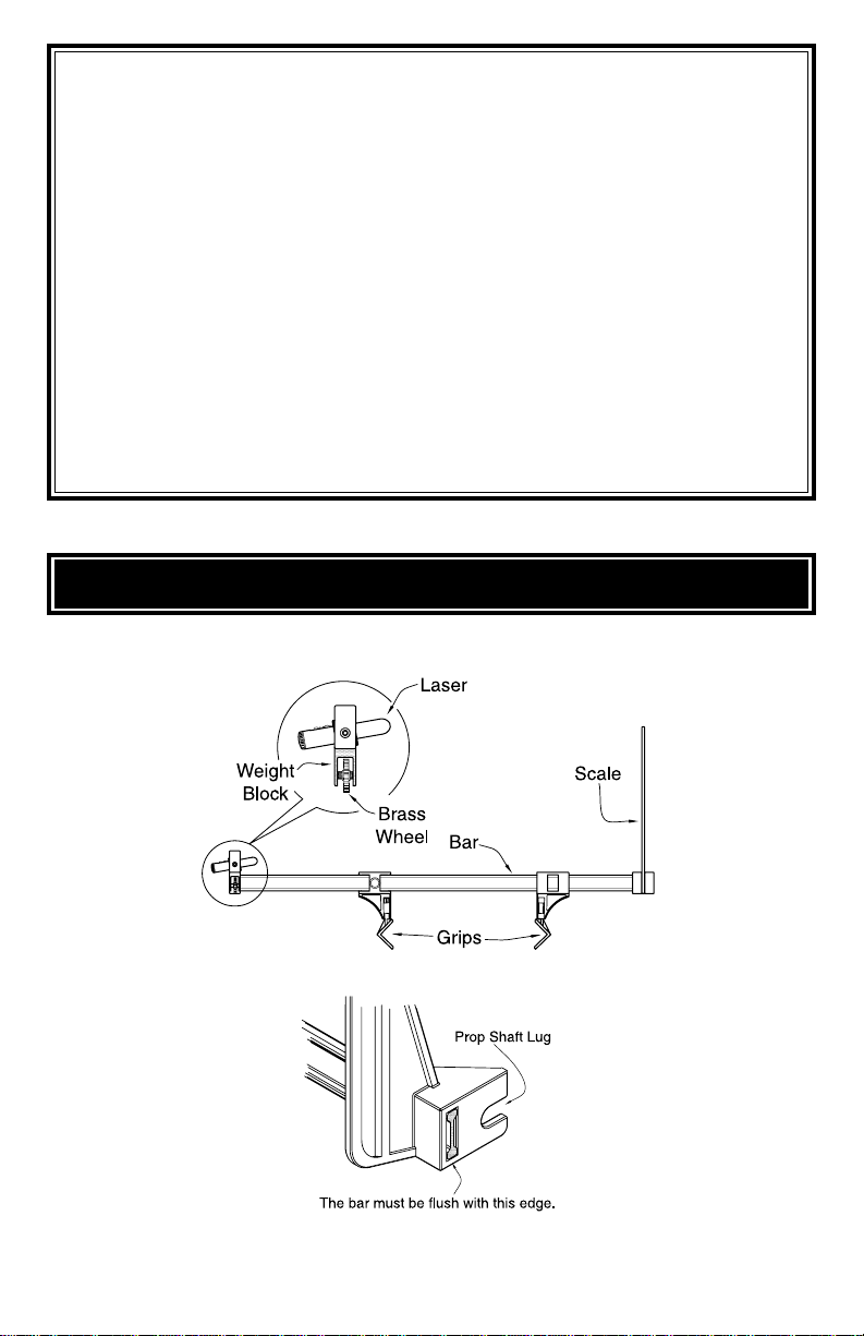
3. Without bumping the laser assembly, attach the meter to the wing close to the fuse-
lage. If the meter is attached to an aileron, make sure the aileron stays
at neutral.
4. Let the laser come to rest and note the reading.
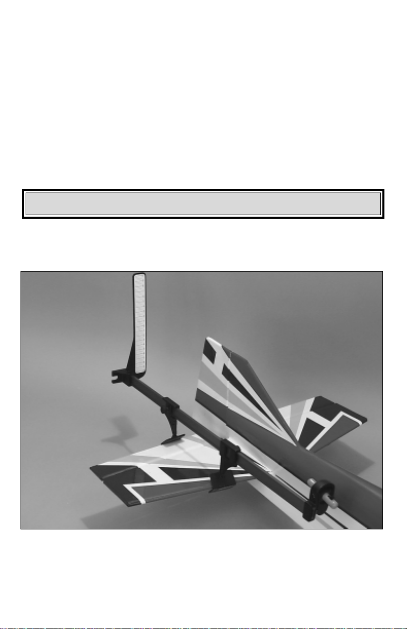
5. Check the other wing panel near the fuselage as well. Any difference measured
between the two sides of the wing could indicate a misalignment during wing joining
or an inaccurate wing saddle.
6. If your model is in the framed up stage, then it is easy to sand the wing or stab sad-
dle as needed to get the correct readings. If your plane is finished, shimming the wing
saddle is your the best course of action to correct the incidence. Changing the
Stabilizer incidence on a finished model entails cutting out the stab, adjusting the stab
saddle and reattaching. This is rather difficult and should not be attempted unless the
problem is severe. An easier solution is to shim the wing so that the incidence differ-
ence between the stab and wing matches the designer’s
specs. If you do this, howev-
er, make sure that the engine down thrust angle is
correct. It will most likely have to
change a bit to correspond to the new wing angle.
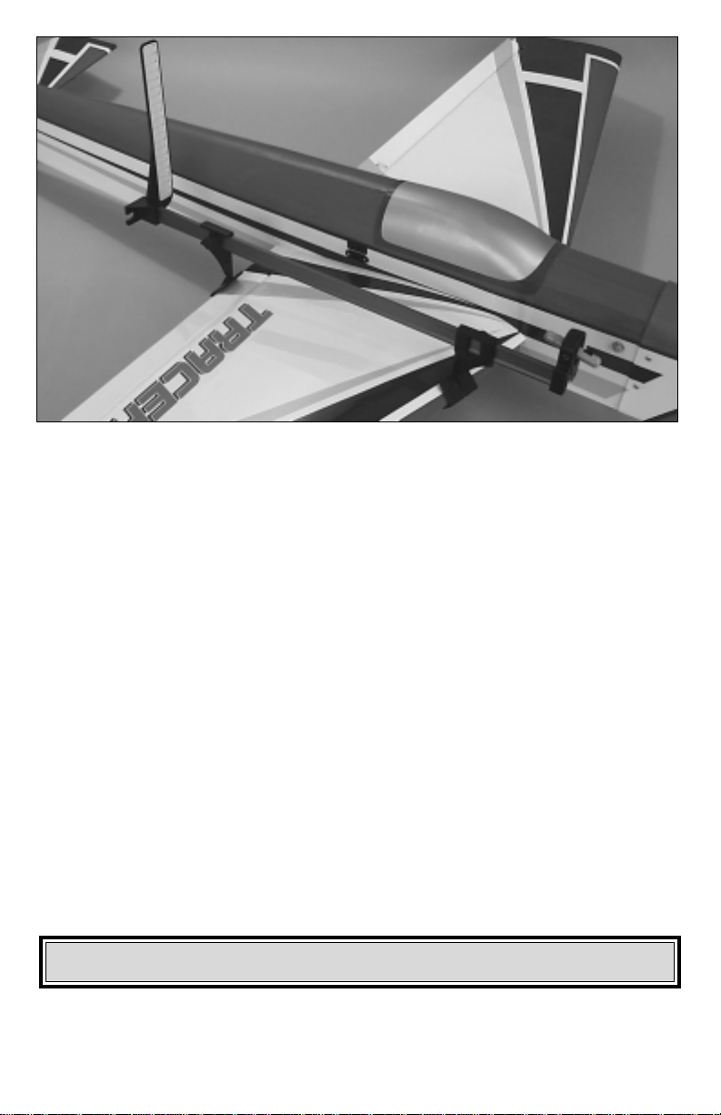
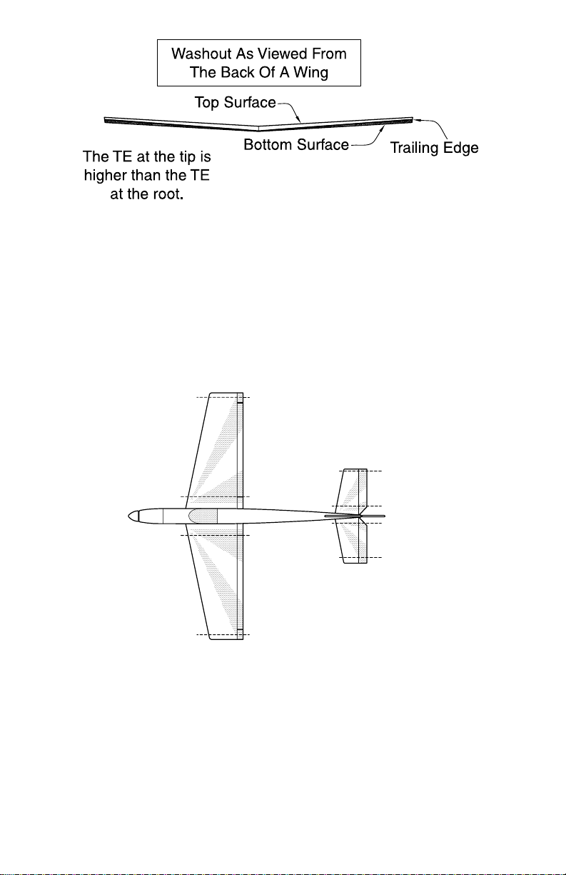
One of the most common problems with model aircraft is wing twist. Wing twist can
cause trim difficulties at different speeds, poor stall characteristics and other general
tracking problems.
Checking Wing/Stabilizer Twist

8
In some cases, however, a wing twist is desirable to add stability (washout: where the
wing tip flies at a lower angle of attack than the wing root). Typically, airplane manu-
facturers give specifications on how much washout should be in a wing. Try to get as
close as you can, but remember, it is more important that both tips have the same
amount of washout to avoid trim problems.
1. Check each wing panel at the root and the tip.
2. Record the data and fix any problems in your wing. For open structure wings, a twist
can be fixed by using a heat gun. Have a helper twist and hold the wing panel to the
correct position. Carefully use your heat gun to shrink out any wrinkles in the cover-
ing. Let the covering cool and then ask your helper to let go. Repeat until the wing is
correct. For fully sheeted wings, there is not a lot you can do to straighten the panel.
Generally, it is not a problem if the difference between wing tips is less than 1/2°.
Right Tip
Right Tip
Right Root Right Root
Left Root Left Root
Left Tip
Left Tip

9
The engine thrust line is critical. If the angle is too high, the nose of the plane will drop
when reducing the power for landing. If it is too low, the plane will balloon up when the
power is reduced. Ideally the thrust angle should be set so there is little to no trim
change from 1/3 to full throttle.
Right thrust is added in many airplanes to counteract the torque effect of the propeller
wash cork screwing around the fuselage. The side thrust should be adjusted so that
the plane tracks straight with the rudder trimmed as close to neutral as possible. Most
manufacturers set this angle so the plane will track straight during upline maneuvers
(stall turns, etc...). Again, check the plan sheet for the recommended specification.
1. Remove the spinner and prop from the front of the engine.
2. Calibrate the meter to 0° on the stabilizer. If checking the side thrust, rotate the fuse-
lage to the side and calibrate the meter on the fin.
3. Bolt the meter to the engine and record the angle. Note: The weight of the meter
may alter the results as gravity tries to pull it down. Try supporting the end of the meter
until you are confident you are getting accurate results.
4. Adjust the thrust angle by adding flat washers between the engine mount and the
firewall. Note: It is best to perform this check before the cowl is mounted as any
changes now will result in a misalignment of the spinner-to-cowl fit.
Checking Engine Thrust

10
The Great Planes Laser Incidence Meter works great for accurately measuring the
pitch of the rotor blades.
1.Attach the meter to one of the main blades close to the rotor head. Position the grips
so they are centered on the bar. This way the weight of the meter won’t try to twist the
blade resulting in inaccurate readings.
2. Using two sticks of wood and rubber bands, construct a flybar clamp that will hold
the flybar level without moving. Typically the clamp is positioned between the flybar
and tail boom.
3. Turn on your radio system and position the throttle/collective stick to the point you
want 0° pitch.
4. Calibrate the meter to 0°.
5. Slowly move the throttle/collective stick and adjust your linkages and radio to
achieve the desired specifications of your machine.
HELICOPTER COLLECTIVE PITCH

11
Great Planes C.G. Machine™
Precision Aircraft Balancer
Accurate balancing makes trainers more sta-
ble, low-wings more agile, and pylon planes
move at maximum speed. The innovative C.G.
Machine helps you achieve optimum balance
easily, without measuring or marking–and
without the errors that fingertip balancing can
cause. You’ll quickly pinpoint your plane’s
exact center of gravity. Then you’ll know at a
glance whether weight should be added,
removed or relocated. The C.G. Machine
works with kits andARF models of any size and wingspan. Its slanted wire balancing posts sup-
port models weighing up to 40 pounds. GPMR2400
Great Planes Accu-Throw™Control Surface Deflection Meter
One leading cause of crashes is flying an airplane with its control throws set differently from
those recommended in the instructions. The Great Planes AccuThrow lets you quickly and eas-
ily measure actual throws first, so you can make necessary corrections before you fly. Large,
no-slip rubber feet provide a firm grip on covered surfaces without denting or marring the finish.
Spring tension holdsAccu-Throw’s plastic ruler steady by each control surface. Curved to match
control motions, the ruler provides exact readings in both standard or metric measurements.
GPMR2405
1 YEAR LIMITED WARRANTY – *USA AND CANADA ONLY
Great Planes warrants this product to be free from defects in materials and workmanship for a peri-
od of one (1) year from the date of purchase. During that period, Great Planes will, at its option, repair
or replace without service charge any product deemed defective due to those causes. You will be
required to provide proof of purchase (receipt or invoice). This warranty does not cover damage
caused by abuse, misuse, alteration or accident. If there is damage stemming from these causes with-
in the stated warranty period, Great Planes will, at its option, repair or replace it for a service charge
not greater than 50% of its then current retail price. Be sure to include your daytime phone number in
case we need to contact you about your repair. This warranty gives you specific legal rights, and you
may also have other rights which vary from state to state.
*For warranty and service information if purchased outside the USA and Canada, see the additional
warranty information insert (if applicable), or ask your retailer for more information.
OTHER ITEMS AVAILABLE FROM GREAT PLANES

DATA SHEET
Copy This Form To Record Your Data
Aircraft Name:
Date:
Reference Line:
Stab
Left Root: Right Root:
Left Tip: Right Tip:
Wing
Left Root: Right Root:
Left Tip: Right Tip:
Engine
Engine Up/Down Thrust:
Engine Side Thrust:
Right Tip
Right Tip
Right Root Right Root
Left Root Left Root
Left Tip
Left Tip
Engine
Thrust
Table of contents
Other GREAT PLANES Measuring Instrument manuals
Popular Measuring Instrument manuals by other brands

System Sensor
System Sensor PC4RLA Installation and maintenance instructions

Endress+Hauser
Endress+Hauser Deltabar M PMD55 operating instructions

Certa
Certa CTLASTAPEMA user guide

TPM
TPM AMT506 manual

Beijing Choice Electronic Technology
Beijing Choice Electronic Technology Fingertip Pulse Oximeter Operator's manual

Endress+Hauser
Endress+Hauser Hart Micropilot FMR60B operating instructions