manuals.online logo
Brands
  1. Home
  2. •
  3. Brands
  4. •
  5. GREAT PLANES
  6. •
  7. Toy
  8. •
  9. GREAT PLANES Ultimate 40 User manual

GREAT PLANES Ultimate 40 User manual

WARRANTY
GreatPlanesModelManufacturingCo.guaranteesthiskittobe freefromdefectsin bothmaterialand
workmanshipat thedate of purchase.Thiswarrantydoes not coverany componentpartsdamaged by use or
modification. Innocase shall Great Planes' liability exceed the original cost of the purchased kit. Further, Great
Planes reserves the right to change or modify this warranty without notice.
Inthat Great Planes hasnocontrol over the finalassembly or material used forfinal assembly, noliability shall be
assumed nor accepted forany damage resulting fromthe use by the user of the finaluser-assembled product.Bythe
act of using the user-assembled product, the user accepts all resulting liability.
Ifthe buyerisnotprepared to accept the liability associated with the useof this product, the buyer isadvised
to return this kit immediately innew and unusedcondition to the place of purchase.
While this kithasbeen flight tested to exceed normal use, ifthe plane will beused forextremely highstress flying, such
as racing, the modeler isresponsible fortaking steps to reinforce the high stress points.
READTHROUGH THIS MANUALBEFORE
STARTINGCONSTRUCTION. IT CONTAINS
IMPORTANT WARNINGS AND INSTRUCTIONS
CONCERNING THE ASSEMBLY AND USE OF
THISMODEL.
P.O.Box788Urbana, IL61803 (217)398-8970
©Copyright 1998ULT4P03V1 1
Introduction
......................................................................3
Precautions.......................................................................3
Decisions You Must
Make................................................3
Engine Selection
.........................................................3
Preparations
.....................................................................3
Required Accessories..................................................3
BuildingSupplies and Tools.........................................4
Optional Supplies andTools
........................................4
Types
of
Wood
.......................................................4
Common Abbreviations................................................4
BuildingNotes..............................................................5
Get Ready to
Build.......................................................5
Inch/MetricRuler..........................................................5
Die-Cut Patterns......................................................6&7
Buildthe TailSurfaces.....................................................8
Build
the Stabilizer
.......................................................8
Build the Elevator.........................................................8
Build the Fin. .
............................................................9
Buildthe Rudder..........................................................9
Hingethe TailSurfaces..............................................10
Finish the TailSurfaces..............................................10
Fitthe Torque Rods
...................................................11
Install Tailwheel Bracket on Rudder...........................11
Buildthe Bottom Wing...................................................12
Wing Preassembly.....................................................12
Buildthe Wing.. . . . ...............................................12
Sheet the Topof the Wing..........................................14
Sheet the Bottom of the Wing....................................15
Complete the Bottom Wing........................................16
Build
the Ailerons
.......................................................17
Build
the Fuselage
.........................................................18
Fuselage Preassembly.. ...........................................18
Assemble the Fuselage Sides...................................19
Install the Formers
.....................................................20
Mount the Wing on the Fuselage...............................22
Installthe Stabilizer and Fin.....................................23
Assemble the Turtledeck............................................24
Buildthe Top Deck.....................................................25
Buildthe Top Wing.........................................................27
Wing Preassembly.....................................................27
Build
the Wing ...
....
..............................................27
Sheet the Topof the Wing..........................................30
Install the Aft Root Ribs..............................................30
Finish Sheeting the Top
of
the Wing
..........................31
Sheet the Bottom of the Wing.. .................................31
Complete the Bottom of the Wing ..............................32
Build
the Ailerons
.......................................................33
Engine
Installation
.........................................................33
Assemble the Plastic Parts
...........................................34
Assemble the Wheel Pants........................................34
Assemble the Cowl
...................................................36
Balance the ModelLaterally..........................................37
Covering.......................................................................37
Prepare the Surface..................................................37
Covering Technique...................................................37
Suggested Covering Sequence................................38
Painting........................................................................38
Final
Hookups and Checks
...........................................38
Install
the Hinges
.......................................................38
Installthe Hardware...................................................39
Attach the Canopy .....................................................39
Radio Installation ...........................................................40
Install the Rudder, Elevator andThrottle Servo .........40
Install the Aileron Servo
.............................................42
Check the Wing Incidence.............................................43
Set the Control Throws.................................................43
Balance
Your
Model
.......................................................44
Preflight...........................................................................44
Charge the Batteries..................................................44
Balance the Propeller.................................................45
Find
a
Safe Place to
Fly.............................................45
Ground Check the Model
...........................................45
Range Check Your Radio...........................................45
Engine Safety Precautions........................................45
AMA Safety Code............................................................46
General.....................................................................46
Radio
Control............................................................46
Flying...............................................................................46
Takeoff.......................................................................47
Flight.........................................................................47
Landing.....................................................................47
Flight
Log...................................................................47
2-View Drawing
...............................................Back
Cover
Your Ultimate 40 isnota toy, butrather a sophisticated,
workingmodel that functionsverymuch like a fullsize
airplaneBecauseofitsrealisticperformance,the
Ultimate40, ifnot assembledand operatedcorrectly,
could possibly cause injury to yourselfor spectators and
damage property.
Ifthis isyour firstbiplane model, we recommend that you
get helpfroman experienced, knowledgeable modeler with
your firstflights. You'll learn fasterand avoid risking your
model before you're ready to take the controls for yourself.
For informationon flyingclubs inyour area,you can
contact the national Academy of Model Aeronautics (AMA),
whichhas more than2,500 charteredclubsacrossthe
countryContactAMAat the address or toll-freephone
number below:
Academy of ModelAeronautics
5151 East Memorial Drive
Muncie, IN47302-9252
Tele (800)435-9262
Fax (765) 741-0057
Orviatheinternetat:http://www.modelaircraft.org
2
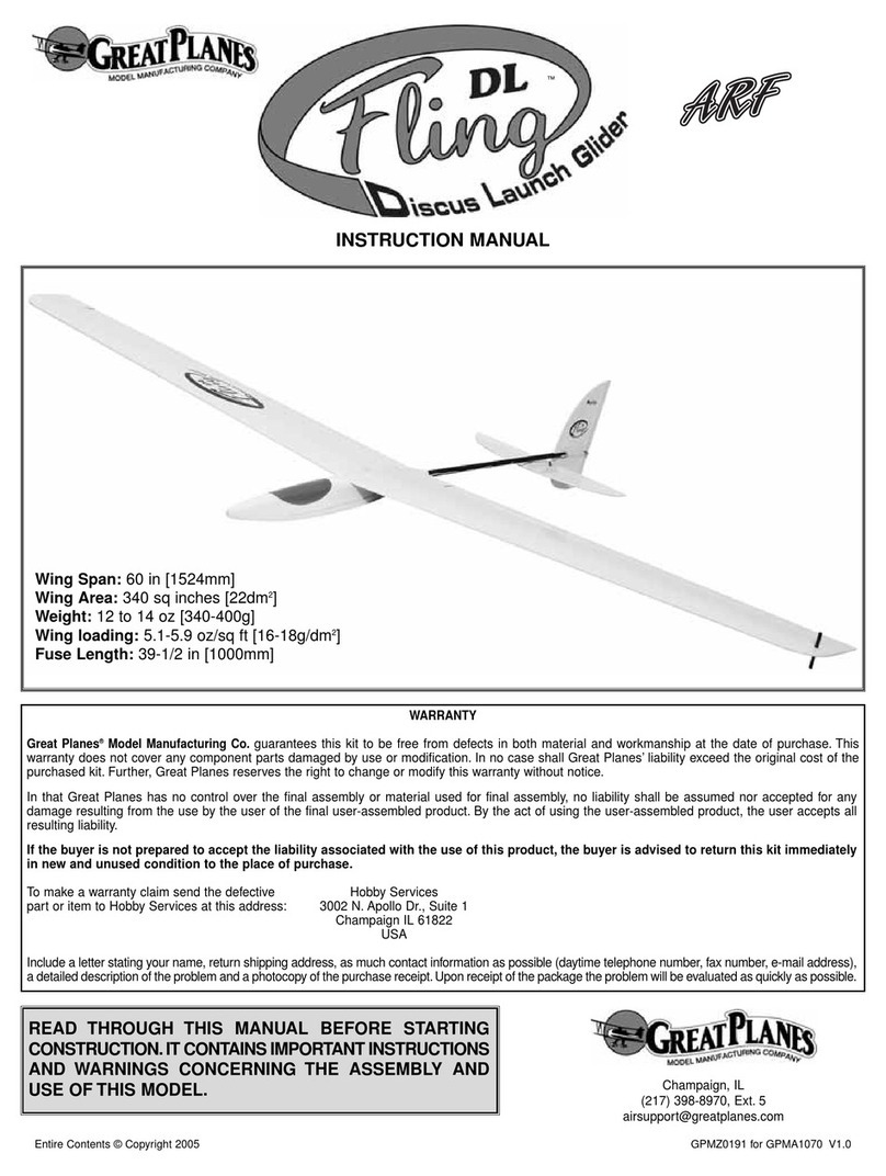
The Great Planes Ultimate 40 isa high performance,
propeller-drivensport biplane that closely resembles the
fullsizeUltimateThe Ultimate40 is verystableand
forgiving,allowing even intermediate skill level pilots to
enjoy it
Thisisnota beginner's airplane! While the Ultimate 40
iseasy to build and fliesgreat, we must discourage you
fromselecting this kitas your first R/C airplane Itlacks the
self-recovery characteristics of good basic trainers such as
the Great Planes PT"Series Onthe other hand,ifyou
have already learned the basics of R/C flying, and you are
able to safelyhandle a 40-sizelow wingairplane, the
Ultimate 40 isanexcellent choice to try your skills atflying
abiplane.
Remember: Take your time and follow directions to end
upwitha well-built model that is straight and true.
Pleaseinspectallparts carefully before starting to build!
Ifany parts are missing, broken or defective, or ifyou
haveanyquestionsaboutbuildingor flyingthis
airplane, please call us at (217) 398-8970. If you are
calling for replacement parts, pleasereference the part
numbersandthekitidentificationnumber(stamped on
the endof the carton) andhave them ready when calling.
1Youmustassemblethemodelaccordingtothe
instructions Donot alter or modify the model, as doing so
may result inanunsafe or unflyable model Ina fewcases
the instructions may differ slightly fromthe photos Inthose
instancestheplans and writteninstructionsshould be
considered as correct.
2Taketime to buildstraight, true andstrong
3UseanR/C radiosystem that isinfirst-class condition,
and a correctlysized engine and components (fuel tank,
wheels, etc ) throughout your buildingprocess.
4.You must properly install allR/C andother components
so that the modeloperates properly on the ground andin
the
air.
5You must test the operation of the model before every
flight to insure that all equipment isoperating, and you must
make certainthatthemodel has remainedstructurally
sound Besure to check clevises or other connectors often
andreplacethemifthey show signsof wear orfatigue.
NOTE We, as the kit manufacturer, can provide you
with a top quality kitandgreat instructions, butultimately
the quality of your finished model depends on how you
build it, therefore,we cannotin any wayguarantee
the performanceof yourcompletedmodel,and no
representationsareexpressedor implied as to the
performance or safetyof your completed model.
Items in parentheses (GPMQ4243) are suggested part
numbers recognized by distributors and hobby shops and
are listed for your ordering convenience GPM is the Great
Planes brand, TOP is the Top Flite" brand, and HCA is the
Hobbico brand.
DFour-channel radiowith four servos
DEngine - SeeEngineSelection above
DPropeller (Top Flite Power Point"), Refer to your
engine's instructions forproper size
DFueltank 10oz (GPMQ4104)
DMedium fuel tubing (GPMQ4131)
D2-1/4" Mainwheels (GPMQ4222)
D1"Tailwheel(GPMQ4241)
DTopFliteMonoKote (Approximately 3 rolls)
DPilotfigure (Williams Bros #185)
D1/4" Latex foam rubber padding(HCAQ1000)
DSwitch andcharge jack (GPMM1000)
DTopFlite LustreKote"Paint - SeePainting(page37)
D1/16" Wing seating tape (GPMQ4422)
D6"Servo extension
D2-1/2" White spinner (GPMQ4520)
DFuelfill valve (GPMQ4160)
3
Thesearethebuildingtoolsthatare required.We
recommend Great Planes Pro" CA and Epoxy glue.
D2 oz. ProCA (Thin, GPMR6003)
D2 oz Pro CA+ (Medium, GPMR6009)
D1 oz Pro CA- (Thick, GPMR6014)
D6-Minute Pro Epoxy (GPMR6045)
D30-Minute Pro Epoxy (GPMR6047)
DHand or electric drill
DSealing iron (TOPR2100)
DHeatgun (TOPR2000)
DHobby saw
DHobby knife, #11 Blades
DRazor plane (Master Airscrew®)
DPliers (Common andNeedle Nose)
DScrewdrivers (Phillips and flat tip)
DT-pins (HCAR5150)
D60" Retractable Tape Measure (HCAR0478)
DStraightedge with scale
DMasking tape (TOPR8018)
DSandpaper (coarse, medium, fine grit)
DEasy-Touch" BarSander (orsimilar)
DPlan Protector (GPMR6167)
DLightweight balsa fillersuch as Hobbico^HobbyLite"
(Hobbico HCAR3400)
D1/4-20 Tapand Drill (GPMR8105)
DIsopropyI rubbing alcohol (70%)
DWhite body putty (Squadron SQUR1500)
DBallpoint pen
D90° Buildingsquare (HCAR0480)
DMicro balloons (TOPR1090)
DCanopy glue
DDrill bits 1/16", 5/64", 3/32", 7/64",1/8",9/64",5/32",
3/16", 13/64",1/4",5/16", 3/8"
DBuilderstriangleset (HCAR0480)
Customsandingblockscan bemadefrom balsaorhardwood
blocksanddowels for sandingdifficult to reachspots
Balsa Basswood Plywood
DCA Applicator Tips (HCAR3780)
DEpoxy brushes (GPMR8060)
DEpoxy mixing sticks (GPMR8055)
DCA Debonder (GPMR6039)
DHotSock "(TOPR2175)
DSingle-edge razor blades (HCAR0312)
DCurved tip canopy scissors for trimming plasticparts
(HCAR0667)
D4 oz Pro Wood Glue(GPMR6161)
Elev= Elevator
LE= Leading Edge(front)
Ply = Plywood
TE = TrailingEdge(rear)
Fuse= Fuselage
LG= LandingGear
Stab= Stabilizer
"= Inches
4
There are two types of screws used inthis kit.
Sheet metal screws are designated bya number anda
length.Forexample #6 x 3/4"
D1.Unroll the plansheets Reroll the plansheets inside
out to make them lieflatPlace wax paper or Great Planes
Plan Protector over the planto prevent glue fromsticking to
theplan.
Machinescrews are designated bya number,threads per
inchand a length. Forexample 4-40 x 3/4"
When you see the term "test fit"inthe instructions, it
means you should firstposition the parton the assembly
without using any glue and then slightly modify orsand
the partasnecessary forthe bestfit
Whenever the instructions tell you to gluepieces together,
CA or epoxy may beused When a specific type of glue is
required, the instructions will state the type of glue that is
highly recommended. When 30-minute epoxy isspecified,
itishighly recommended that you use only 30-minute (or
slower)epoxybecause you willneed either the working
time orthe additional strength.
D2 Remove allparts from the box As you do, determine
the name of each partbycomparing itwith the plan and
the parts list included withthiskitUsinga felt-tipor
ballpointpen,lightly write the part name or size on each
piece to avoid confusionlater Use the die-cutpatterns
shown on pages 6 and7 to identify the die-cut parts and
mark them before removing them fromthe sheet Save all
scraps Ifany of the die-cut parts are difficult to remove, do
not forcethem'Instead, cut around the parts Use your
Easy-Touch Bar Sander or sanding block to lightly sand
the edges to remove any die-cutting irregularities.
D3.As you identify andmark the parts, separate them
into groups,such as fuse (fuselage),wing,fin,stab
(stabilizer) and hardware Resealable food storage bags
arehandytostorepartsin as yousort,identifyand
separate them intosubassemblies.
Several times duringconstruction we refer to the "top"or
"bottom' of the model or a partof the model For example,
during wing construction we tellyou to "glue the top main
spar" or "trim the bottom of the former"Itisunderstood that
the "top" or "bottom" of the model isas itwould bewhen the
airplane isright side upandwill bereferredto as the "top"
even if the model isbeing worked on upside-down (ie the
"top" mainspar isalways the 'top" mainspar,even when
the wing isbeing built upside-down).
InchScale
MetricScale
5
6
7
Glue together the pairs of die-cut 1/8" balsa stabilizer
centerS-1,finbottomS-2,rudder bottomR-3 and
ruddertipR-4 to make1/4" thickparts.
D3 Remove the stab fromyour building board Inspect all
theglue jointsand add CA to any jointsthatdon't look
strong Sand the LEand TE flush Sand the entire top and
bottom surfaces of the stab until they are flat and even Be
careful that you don't sand any area of the stab too thin.
D1 Pinthe die-cut 1/4" balsa stabilizer center S-1 over
thestabilizerplanCutthestabouterframefroma
1/4"x 1/2" x 36" balsa stick, allowing approximately 1/16"
extra atthe jointsThe jointswillbesanded flush after the
stab isremoved fromthe building board Glue the outer
frame and stab center together andpinitinposition over
the plan Use theplans or a straightedgeas a guide to
makesurethe stabTE isstraightasyou glueitinposition.
Note: Refrain fromusing excessive accelerator Hours
after it's sprayed on residual accelerator can prematurely
andunexpectedly cure the CA you use later, on nearby
glue joints Unless you must handle or remove the part
fromyourbuilding board rightaway, werecommend
using noaccelerator atall.
D2 Make the 1/8" stab ribs froma 1/8"x 1/4"x 36"balsa
stick.Gluethe ribsinposition.
Hint:Use a sharp, single-edgerazor blade to cut the
stab ribs.
DD 1 Cut a 1/4" x 1/2" x 36" balsa stick to make the
elevator LEandTE Pin the LEandTE inposition over the
plan Allow the LEto extend 1/16" past the root andthe TE
to extend 1/16" past the tip.
DD 2. Cut the rootand tip framefromtheremaining
1/4"x 1/2"x 36" balsa stick Glueandpinthe elevator in
position over the plan.
DD 3 Cut gussets from a 1/4"x 1/2"x 36"balsastick
andglue them inplace
DD 4 Make the 1/8"elevator ribs from a 1/8"x 1/4"x
36"balsastick andgluethem inplace
8
D3.Remove the fin from your buildingboard.Inspectall
the glue jointsand add CAtoany jointsthatdon'tlook
strong. Sand the jointsflush and the entiretop and bottom
surfaces of the finflatandeven. Becareful that you don't
sand any area too thin.
DD 5. Remove the elevatorfromyourbuilding board.
Inspect all theglue jointsand addCA to any jointsthat
don't look strong. Sand the LE,TE, root and tip flush.Sand
the entire top and bottom surface of the elevator flatand
even. Becareful that you don't sand any area too thin.
D6.Go back to step 1 and build the second elevator
following the same procedure.
D1.Pin the die-cut 1/4" balsa rudder bottom R-3 and
ruddertip R-4 over the rudderplan. Cut the rudder outer
framefroma 1/4" x 1/2" x 36" balsastick,allowing
approximately1/16"extraat thejoints.Glue theouter
frame, rudder bottom and rudder tip together and pinitin
position over the plan.Use the plans or a straightedge as a
guide to make sure the rudder LEisstraight as you glue
itinposition.
D1.Pinthe die-cut 1/4" balsa finbottom S-2 over the fin
plan.Cut the fin outer frame from a 1/4"x 1/2"x 36"balsa
stick, allowing approximately 1/16" extra atthe joints. Glue
theouterframeand finbottomtogetherand pinitin
positionover the plan.Use the plans or a straightedge as a
guide to make sure the fin TE isstraight asyou glueitin
position.
D2. Cut the toptwofinribsfromtheremaining
1/8" x 1/4" x 36" balsa stick.Cut thebottomrib froma
1/4"x 1/2"x 36"balsastick. Gluethe fin ribsto the fin LE
and
TE.
D2. Cut the rudder ribs and diagonal braces fromthe
remaining 1/8"x 1/4"x 36"balsastick. Glue the ribsand
braces inposition.
D3.Cut the remaining 1/4" x 1/2" x 36" balsa stick to
makethe LEgusset. Gluethe gusset inposition.
D4. Remove the rudder fromyour building board. Inspect
allthe glue jointsand addCA to any jointsthat don't look
strong. Sand the jointsflush and the entire top andbottom
surfaceof the rudder flatand even. Becareful that you
don'tsandanyarea too thin.
9
D1.Placethe stab andelevators over their locationson
the planandlightly mark the hinge locations on the TE of
the stab andLEof the elevators.
D2.Mark the centerline of the hingeson the stab's TE
andelevator's LEusingthe following centerline method.
D4.Cutthehingesfor the elevators andrudderfrom the
supplied 2" x 9" hinge material. Use the hinge drawing
on thefuseplan as a guide.Trimoffthecornersand
temporarily join the elevators to the stabs with the hinges,
adjusting any hinge slots ifnecessary. Donotglueinthe
hingesuntilyou are instructed to doso.
D5.Return to step 1 and use the same procedure to
hingethe rudder andfin.
HOW TO MARK A CENTERLINE
It'simportant that the hingesarecentered andparallelto
the part you are hinging. The best waytostart isby
accurately marking the hingecenterline.
D1.Refer to the Expert Tipthat follows and shape the LE
of the elevators and rudder to a "V" shapeas shown on
the plans.
A. Laythe stab anda ballpoint pen on a flatsurface.
Marka "test line"onthe trailing edge of the stab.
B.Flipthe stab over andmarkanother lineinthe same
location as the first.Ifyou see only one line, then itis
on center. Proceed and mark the centerline ateach
hingelocation. Ifyou see two lines, use playing cards
or business cards to adjust the height of the penuntil
you canmarkthe centerline.
C.Use the same technique to mark the centerline along
the entire length of both elevators.
HOW TOBEVEL THE LEADING EDGE
A. Place the leadingedge of one of the elevators on your
work surfaceand use your ballpoint pen to mark a
"bevel to" line on both sides about 1/8" high.
D3.Cutthe hingeslots inthe elevator and stab using a
#11 blade. Begin by carefully cutting a very shallow slit at
the hinge location to accurately establish the hinge slot.
Make three or fourmore cuts, going a little deeper each
time. As you cut, slide the knifefromside to side until the
slot hasreached the proper depth andwidth forthe hinge.
B.Usingthe bevelto linesandthecenterlineas a guide,
make the "V" on the leadingedge of the elevators with
arazor plane or your barsander.
D2.Use the same procedure to bevel the leadingedge of
therudder.
10
D3 Draw a centerline on the LEof the stab andfin and on
the TE andtip of the elevators andrudder Sand a radius
onthe edges as shown on the planusingthe centerline as
aguide to keep the radius symmetrical Donot round the
TE of the stab or fin. HOW TOCUT A GROOVEFOR A TORQUEROD
A. Usea hobbyknifeto sharpen theinsideof a pieceof
1/8"brass tube Roll the tube as you carve the end.
D1 Positionthe stab andelevators over the fuselage top
view Markthe locationof the elevator joiner on the elevators.
B.Usethe sharpened tube to carefully gouge the leading
edge You IIhave to make several passes to make the
recess deep enough for the torque rod.
D2 Drill 3/32"pilotholeinto theelevatorLE, on the
centerline, atthe torque rod marks Asyou drill the holes
keepthe drill aligned withthe top andbottom surfaces of
the elevator Enlarge the holes with a 1/8"drillbit.
D3 Cut a 1/8" grooveinthe leading edge ofboth
elevatorstorecessthejoinerwire(seeexperttip that
follows) Donotglue the joiner wire inposition atthis time.
D1 Positiontherudderovertheplan and alignthe
tailwheelbracketovertherudderMark thetailwheel
bracket "arm" location on the LEof the rudder.Drilla 7/64"
hole,3/4" deep atthe mark.
D2 Cut a groove from the tailwheel bracket hole to the
bottomof the rudder thatwillallowthenylontailwheel
bearing to fitflush with the LEof the rudder Donotglue
the tailwheel bracket inatthis time.
11
The Ultimate 40 bottom wing isbuilt as one piece.
D1.Use 30-minute epoxy to glue together the die-cut 1/8"
plywood ribs R-5 andR-6.
TWO WARPED SPARS INSTALLED
THIS WAY WILL RESULT INA
STRAIGHT WING
D1.Pinthe die-cut3/32" balsaribsR-1 inpositionover
the main spar.
Note: The jig tabs should becontacting the plan. Use
small T-pins to pinthe aft jig tabs to the building board
over their location on the plan.
HOLD KNIFE AT AN ANGLE
WHENCUTTINGAPART
LEADINGEDGE
D2.Theshaped and notched balsawing LEandTE are
fastened together bythin strips of balsa. Separate them by
cutting with a hobby knife, as shown inthe sketch above.
TWO WARPED SPARS INSTALLED
THIS WAY WILL RESULT INA
WARPED WING
D2.Match sets of 1/4"x 3/8" x 24" balsawing spars so
anywarps will counteract each other.
D3. Trim the end of two main spars to the angle shown
on theplan.Use 6-minuteepoxytogluetheendsof
the main spars together. Before the epoxy cures, use the
cross-pinning technique (see sketch above) to pinthe main
sparsagainstthe buildingboard.
DD 3.Center the LEvertically on the frontof the ribswith
each rib inserted inits respective notch. Use a straightedge
to check that the LEisstraight before gluing itinposition.
DD 4. Cut the LEatthe root as shown on the plan.Save
the piece you cut off forthe wing center section.
D5.Repeat the process to installthe otherLE.
12
D6. Position theTE on the aftend ofthe ribs, flushwith
the top and bottom edge of the ribs. Use a straightedge to
check that the TE isstraight beforegluing itinposition.
Trim the root end to match the plan.
D7.Fitthe second TE, trimming the root end to butt
againstthe first TE. Usea straightedge to check that the
TEisstraight before gluing itinposition.
D8. GlueribsR-1 to the bottom mainspar,perpendicular
to the buildingboard.
D11.Glue the die-cut3/32"balsaribsR-4flush with both
sides of R-5.
D9. Use 30-minute epoxyto glue the 1/8"plywood joiner
betweenthe R-1root ribs, perpendicularto the building
board. The center of the joiner should beflushto the aft
edge of the main spar and the joinerends should beflush
with the forwardedge of the main spar. Make sure the top
of the joiner isflush with the bottom of the slots for the top
mainspar.
D12. Use 6-minute epoxy to glue rib R-6tothe joiner
and the TE. Make surethattherib is seatedon and
perpendicular to the building board. Glue rib R-5to the front
of the joiner and spars, perpendicular to the building board
andparallel with the R-1 root ribs.
D13.Trim the leftover LEto fit between ribs R-1andR-5,
centered on the frontof ribsR-4. When satisfied with the fit,
gluethem inplace.
D10. Use 30-minuteepoxyto gluethetopspar tothe
joinerand thin CA to glue the joinerto the ribs. Hold the
spar inplace with a weight until the epoxy cures.
U14. Use6-minute epoxy to glue the die-cut 1/8"plywood
leading edge joiner (LEJ), centeredvertically,across the
joint between the center LEandthe outer LE.
13
D15Test fit the die cut 1/8"plywood ribs R-2A andR-2B
inposition as shown on the plans Check the fitof the wing
strut between R-2A and the wing spars The strut should fit
snug but be easytoinsertand remove When satisfied
with the fit,remove the strut and glue ribsR-2A and R-2B
to
R-1.
D1.Cut the2" LE and 1" TE sheetingfromeight
1/16"x 3"x 24" balsa sheets The LEand TE sheets willbe
usedon both wings.
D16Insert the die-cut 3/32" balsa rib R-3 between the
spars and carefullyrotateit into positionGlue itto ribs
R-2A, R-2B, the wing spars andthe LEandTE.
D2 TestfittheLEwingsheetto one wing panel Sand a
slight bevel on the frontof the sheet The aft edge of the
sheet should cover the forward half of the mainspar The
root endshould cover one R-4 andR-5 rib.
D17From a 1/16" x 3" x 24" balsa sheet cutand glue
shear webs, perpendicular to the aft edge of the main spars
Theshear webs must begluedsecurely to the mainspars.
D18Sand the top of the wing so that the spars, shear
webs andTE are flush with the top of the ribs.
D3 Remove any pins that are holding the wing to the
building board infrontof the main spar You may need to
placeweightson thewingtokeep the main sparsflat
againstthebuilding board Positionthefrontof theLE
sheet againstthe LEandglue itinposition with thin CA.
D4 Carefully lift the sheet away fromthe ribs and applya
bead of medium or thick CA to the top of the ribs Working
quickly, pull the sheet back towardthe main spar as you
press itdown against the ribsandthe mainspar.
14
D5.Usethin CA to glue the LEsheetto the mainspar.
D6.Fitandglue the second LEsheet to the other wing
panel,following the same procedure.
D9.From 1/16"x 3/16" x 30" balsa stick,cut and glue cap
strips to the top of the R-1 ribs. The edge of the cap strip
on the R-1tip rib should beflushwiththe side of the rib.
Usetwo cap strips, edge-glued at the center of rib R-2A on
the double rib,for the strut. Trimthe capstrip over theslot
for the strut.
Hint:A single-edge razor bladeworks well for this type
of cutting.
D7.Glue the 1/16" TE sheet, cut instep 1,to the TE and
the top of the ribs
D10.Remove the wing fromyour buildingboard. Cut and
sand the LE,TE, mainspars andtop sheeting flushwith the
sideoftipribR-1.
D8.Use a 1/16" x 3"x 30" balsa sheet to make the center
sheeting between the LEsheet and the TE sheet. Save
the remaining sheeting forthe bottom center sheeting. The
center sheeting filler ismade froma 1/16" x 3" x 24"
balsa sheet.
Note:Seethe plansfor clarity.Before you gluethe center
sheetingin position,removeanyT-pinsfromunder
the sheeting.
The bottom of the wing issheeted following the same
procedure as the top of the wing.
D1.Use a hobbyknife andsandingbarto remove the jig
tabs on the bottom of the ribs. Sand the TE, main spars,
shear webs andthe top of the ribsto blendthem together.
D2.Cutoutthe aileron servo opening inthe top center
sheeting using theaileronservocutoutin rib R-6as a
guide. Make the opening slightlysmallerthan the servo
cutout inthe rib. The opening will beenlarged when the
servo tray isinstalled.
15
D3. Positionthe wingon yourbuilding board withthe
bottom side up. Place weights on the wing to keep the main
spars incontact with the building board. Glue thebottom
LEsheeting inposition followingthe same procedure used
forthe top LEsheeting. Remember, you previously cut the
LEsheeting when you sheeted the top of the wing.
D4.Gluethe 1/16"TE sheet, cut instep1 of "sheet the
top of the wing", to the TE and the bottom of the ribs. Use a
leftover piece of balsa sheeting to fill the gapatthe center
of
the
LE.
D5. Use the 1/16" x 3" x 30" and 1/16" x 3" x 24" balsa
sheeting,leftoverfromthe top center sheeting,tomake
the bottom center sheeting between the LEsheet and the
TE sheet.
D6.Test fit the struts inthe slots inthe top of the wing,
making sure they seat against the top wing sheeting. From
1/16" x 3/16" x 30" balsa stick,cut and glue cap strips to
the top of ribs R-1. The edge of the cap strip on the R-1 tip
rib shouldbe flushwiththe side of the rib. Use twocap
strips, edge-glued atthe center of ribR-2A on the double
rib,for the strut.
D7.Trimandsand the LEandTE sheeting flush with the
side of tip ribR-1.
D8.Make the wing tips froma 1/8" x 3" x 18" balsa sheet.
Hold the sheet against tip rib R-1 and draw an outline of the
rib.Cutandglue the wing tips to tip ribs R-1.
D3. Mark the location of the aileron torque rod exits.Cut a
notch inthe top LEof both pieces as shown.
Note;Besure you makea rightandleft piece.
D4.Roughenbothtorquerodtubeswithcoarse
sandpaperand applya dab ofpetroleumjellytothe
exposed wire.Use 30-minute epoxy to glue the torque rod
tubes inthe slot atthe frontof the center TE pieces. Before
theepoxycures, glue the center TE pieces to the TE of the
wing.Wipeoffanyexcessepoxywitha papertowel
dampened with isopropyi rubbing alcohol. Hold the center
TE pieces in place with masking tape until the epoxycures.
D1.Sand the TE sheet flush with the aft edge of the TE.
D5. Extendthetorquerod exitslotsinto theTE of
the wing.
D6. Sand the center TE flush with the top and bottom
TE sheeting.
D2. Positionthetaperedand grooved1-1/4"x 4-1/2"
balsa wing center TE pieces over the plan. Trim the root
ends to match the angle shownon the plan. Test fitthe
center TE on the TE of the wing. D7.Draw a centerline on the die-cut 1/16" birch plywood
wing bolt plate. Sanda bevel on the front and sides of
16
the wing plate.Leave the aft edge of the wing bolt plate
square Use 30-mmute epoxy to glue the wing boltplate to
the bottom of the wing, centered on the center TE The aft
corners of the wing bolt plate are flush withthe aft end of
the center TE. Use clamps or weights to hold the wing bolt
platetight against the wing.
D8.Trim the opening forthe aileron servotrayuntil you
can see the aileron servocutoutinribs R-6Centerthe
die-cut 1/8" plywood aileron servo trayoverthecutout
(save the tray doublers die-cut inside the servo tray)Mark
the outside perimeter of the tray andcut the wing sheeting
from insidethese lines.
D9. Glue thedie-cut1/8"plywoodaileronservo
traysupportstotheendsoftheaileronservotray,
perpendicular tothetrayGlue the traydoublers to the
bottom of the aileron servo tray.
D10.Glue the servo tray to ribs R-6
DD 1 Trim one end of the 1-1/4" x 24" balsaaileron to
the same angle asthe center TE.
DD 2.With a gapof 1/16" between the aileron andthe
center TE, cut the end of the aileron approximately 1/16"
past the wing tip This will allow you to sand the aileron
flush with the wing tip.
DD 3 Place the leftaileron on the trailingedge of the
wing andmark the location of the torque rod.
DD 4.Draw a centerline on the LEof the aileron.
DD 5.Drilla 1/8"holeon the centerline forthe aileron
torquerodUse a sharpened1/8"brasstube tocut a
groove inthe LEforthe aileron torque rod.
DD 6.Usetheleftoverhingematerial,cutfour aileronhinges.
DD 7.Mark the location forthe hinges on the aileron and
wing. Cut the hinge slots andwithout usingglue, test fit
the aileron on the wing.
17
DD 8.Remove the aileron fromthe wing. Markthe"bevel
to" lines and sand the LEof the aileron to a "V" as shown
ontheplan.
D9.Perform steps 1 through 7 to fit the second aileron
onto the wing.
Great looking wing! Guess what? You still have to build the
top wing.
We will build the fuselage next. It will be needed when you
assemble the top wing.
Completely readthissection onFuselage Preassembly and
test fitallthe parts. These parts require the strength and
working time of 30-minute epoxy glue. This extraworking
time will allow you to assemble most of the partsatonce.
D2.Glue the die-cut 1/16" birch plywoodF-8A doubler to
the frontof the die-cut1/8" plywoodformerF-8B. Make
sure the slots inF-8AandF-8Bare aligned.
D3. After the epoxy has cured, drill5/32" holes atthe four
engine mount punch marks. Drill a 3/16" hole forthe throttle
pushrod at the appropriate location. Drill two 1/4" fuel line
holes inthe center of the engine mount holes.
D1.Glue the three die-cut 1/8" plyfirewallformers FF-1,
FF-2and FF-3together. Former FF-2 must besandwiched
betweenFF-1 and FF-3.Make sure thattheembossed
labelon each formerisfacing forward andthe top andside
edges are aligned. The bottom edges will beoffset. Wipe
off anyexcess epoxy before itcures.
Note: Ifthe formersare warped, clamping them together
will not remove the warp. Itisbestto clamp them to a flat
table or board.
D4. Press four6-32 blind nuts into the holes from the
back of the firewall.Tapthe blind nuts witha hammer to
fullyseat them and apply a fewdrops of thin CA around
each blind nut to secure them inposition.
D5.Drill3/16" holesat the punchmarks inthe die-cut1/8"
plywood fuselage formers F-10andF-11.
18
D6.Cut 1/4" fromthe frontof one die-cut 1/8" balsa lower
fuse side, one upperfuse side, one die-cut 1/8"plywood
lower fuse doubler and one upper fuse doubler. Mark
each of these parts right side.
D1.Build twofusesides by gluing togetherthebalsa
lowerand upper fusesides.Make sure to glue the two
rightsidepiecestogether.
D2.Sand the fuse sides smooth.
D7.Drill1/8"holes atthe punch marks on the upper fuse
doublers. Drill 5/16" holesat the punch marks on the upper
fuse sides.
D3. Caution:Make sure to gluetherightsidedoublers to
therightside fuse. Position the fuse sides next to each other
asshown. Glue the die-cut 1/8" lower fuse doublers to the
fuse sides, aligning the edges of the wing saddleandthe
forward edges. Glue the die-cut 1/8" top fuse doublers to
thefuse sides, aligningthe top andfront edges.
D8.Glue the die-cut 1/8"balsa aft fuse bottom together.
D9. Glue the die-cut 1/8" balsafuse top deck together. D4. Gluethe die-cut 1/8" balsa aft fuse doubler to the aft
fuse sides. Align the notch andthe pushrod exit slot.
19
Important: Install allformers with the embossed lettering
facing the nose of the fuse. Donot glue the fuse together
untilinstructed to.
D1. Insert die-cut 1/8" plywood formersF-10, F-11and
F-12 into theirappropriate slotsin the fusesides. Make
sure the modified rightfuse side ison the right side. Use
rubber bands placed around the fuselage sides to holdthe
formers inplace.
D2.Installthe aft fuse bottom.
D4. Install the die-cut 1/8" plywood formersF-9, F-8A/B
andthe firewallas you pullthe fusesides together. You
may need to use clamps, placed along the bottom of the
fuse, along with rubber bands to hold the sides together.
D5.Align the fuse over the bottom view of the fuse plan
with the firewall hanging over the edge of the building board.
With the formers perpendicular to your building board, use
thin CA to glueformers F-12 thru F-8A/B to the fuse sides,
top deck and aftfusebottom. The fusesides shouldbe
perpendicular to the building board fromthe tail to former
F-10. AtF-10 the bottom of the fuse starts to taper in.The
bottom of former F-8A/B isglued flush with the front of the
wing saddle.Donotglue the firewall atthis time.
D6. Aftergluing the jointswiththin CA, go back and
reinforce all jointswithmedium CA.Afterthe CA cures,
remove the rubberbands andclamps.
D3.Installthe fuse top deck.
Note: The frontof the top deck isangled to build right
thrustinthe firewall.Use rubber bandsto temporarily hold
the tail section together.
D7.With the fuse stillpositioned over the fuse planbottom
view,use30-minuteepoxytoglue thefirewalltothe
fuse sides.
D8. Use 6-minute epoxy to glue 3/8" balsa triangle sticks
to thejointsbetween the fusesides, the top deck and
the firewall.
20

Other GREAT PLANES Toy manuals

GREAT PLANES ultimate! User manual

GREAT PLANES

GREAT PLANES ultimate! User manual

GREAT PLANES Yard Stik User manual

GREAT PLANES

GREAT PLANES Yard Stik User manual

GREAT PLANES matt chapman eagle 580 User manual

GREAT PLANES

GREAT PLANES matt chapman eagle 580 User manual

GREAT PLANES Dynaflite Series Installation and operating instructions

GREAT PLANES

GREAT PLANES Dynaflite Series Installation and operating instructions

GREAT PLANES SopWith Camel User manual

GREAT PLANES

GREAT PLANES SopWith Camel User manual

GREAT PLANES Shoestring User manual

GREAT PLANES

GREAT PLANES Shoestring User manual

GREAT PLANES FlyLite User manual

GREAT PLANES

GREAT PLANES FlyLite User manual

GREAT PLANES Reactor User manual

GREAT PLANES

GREAT PLANES Reactor User manual

GREAT PLANES Super Stearman User manual

GREAT PLANES

GREAT PLANES Super Stearman User manual

GREAT PLANES EDGE 540 T Performance Series User manual

GREAT PLANES

GREAT PLANES EDGE 540 T Performance Series User manual

GREAT PLANES AT-6 Texan User manual

GREAT PLANES

GREAT PLANES AT-6 Texan User manual

GREAT PLANES ZERO User manual

GREAT PLANES

GREAT PLANES ZERO User manual

GREAT PLANES J-3 ElectriCub User manual

GREAT PLANES

GREAT PLANES J-3 ElectriCub User manual

GREAT PLANES Giles G-202 User manual

GREAT PLANES

GREAT PLANES Giles G-202 User manual

GREAT PLANES Wright Flyer User manual

GREAT PLANES

GREAT PLANES Wright Flyer User manual

GREAT PLANES EXTRA-300SP User manual

GREAT PLANES

GREAT PLANES EXTRA-300SP User manual

GREAT PLANES EP F-20 Tigershark ElectriFLy User manual

GREAT PLANES

GREAT PLANES EP F-20 Tigershark ElectriFLy User manual

GREAT PLANES Venus 40arf User manual

GREAT PLANES

GREAT PLANES Venus 40arf User manual

GREAT PLANES fairchild PT-19 User manual

GREAT PLANES

GREAT PLANES fairchild PT-19 User manual

GREAT PLANES matt chapman eagle 580 User manual

GREAT PLANES

GREAT PLANES matt chapman eagle 580 User manual

GREAT PLANES BLT User manual

GREAT PLANES

GREAT PLANES BLT User manual

GREAT PLANES Viper 500 ARF User manual

GREAT PLANES

GREAT PLANES Viper 500 ARF User manual

GREAT PLANES Ultra Sport 40 Plus User manual

GREAT PLANES

GREAT PLANES Ultra Sport 40 Plus User manual

GREAT PLANES F-4 Phantom II User manual

GREAT PLANES

GREAT PLANES F-4 Phantom II User manual

Popular Toy manuals by other brands

LEGO SPEED CHAMPIONS 76876 Building instructions

LEGO

LEGO SPEED CHAMPIONS 76876 Building instructions

Eduard 32 301 instructions

Eduard

Eduard 32 301 instructions

Trix Express 32399 Operation manual

Trix

Trix Express 32399 Operation manual

Zapf Creation Baby Annabell 794982 Assembly instructions

Zapf Creation

Zapf Creation Baby Annabell 794982 Assembly instructions

Trix minitrix BR360 manual

Trix

Trix minitrix BR360 manual

Lionel VISION Line owner's manual

Lionel

Lionel VISION Line owner's manual

Tamiya T55A user manual

Tamiya

Tamiya T55A user manual

Model Rockets BOOSTAR-C Assembly instructions

Model Rockets

Model Rockets BOOSTAR-C Assembly instructions

REVELL F-104 G Starfighter manual

REVELL

REVELL F-104 G Starfighter manual

Rail King NW-2 Operating instrutions

Rail King

Rail King NW-2 Operating instrutions

Faller 130578 manual

Faller

Faller 130578 manual

Fisher-Price DORA TALKING KITCHEN H1581 instruction sheet

Fisher-Price

Fisher-Price DORA TALKING KITCHEN H1581 instruction sheet

Crivit DS-1435 User instructions

Crivit

Crivit DS-1435 User instructions

Eduard Schwimmwagen quick start guide

Eduard

Eduard Schwimmwagen quick start guide

FMS LET-13 operating manual

FMS

FMS LET-13 operating manual

Canon CREATIVE PARK 3D Decoupage Assembly instructions

Canon

Canon CREATIVE PARK 3D Decoupage Assembly instructions

REVELL KIT 5321 Assembly manual

REVELL

REVELL KIT 5321 Assembly manual

LEXIBOOK I can talk Oui-Oui IT1010I1 instruction manual

LEXIBOOK

LEXIBOOK I can talk Oui-Oui IT1010I1 instruction manual

manuals.online logo
manuals.online logoBrands
  • About & Mission
  • Contact us
  • Privacy Policy
  • Terms and Conditions

Copyright 2025 Manuals.Online. All Rights Reserved.