Grecom Husky 2150 LP User manual

3A8693B
EN
Instructions
Aluminum HuskyTM 2150 LP
Air-Operated Diaphragm
Pumps
2-inch air-operated double-diaphragm (AODD) pump for fluid transfer. Not for use in
sanitary applications. For professional use only.
120 psi (0.8 MPa, 8 bar) Maximum Fluid Working
Pressure
120 psi (0.8 MPa, 8bar) Maximum Air Input Pressure
See page 2 for model information, including approvals.
Important Safety Instructions
Read all warnings and instructions in this
manual before using the equipment.
Save these instructions.
Tel: 866-777-6060
Fax: 866-777-6383
Springer Pumps, LLC
Website: www.springerpumps.com
Int'l: +001 267 404 2910

2 3A8693B
Contents
Models. . . . . . . . . . . . . . . . . . . . . . . . . . . . . . . . . . . . 2
Warnings. . . . . . . . . . . . . . . . . . . . . . . . . . . . . . . . . . 3
Configuration Number Matrix . . . . . . . . . . . . . . . . . 5
Typical Installation. . . . . . . . . . . . . . . . . . . . . . . . . . 6
Installation. . . . . . . . . . . . . . . . . . . . . . . . . . . . . . . . . 7
General Information . . . . . . . . . . . . . . . . . . . . . . . 7
Before First Use. . . . . . . . . . . . . . . . . . . . . . . . . . 7
Grounding . . . . . . . . . . . . . . . . . . . . . . . . . . . . . . 7
Mounting . . . . . . . . . . . . . . . . . . . . . . . . . . . . . . . 8
Air Exhaust Ventilation. . . . . . . . . . . . . . . . . . . . . 8
Accessories . . . . . . . . . . . . . . . . . . . . . . . . . . . . . 9
Tips to Reduce Cavitation . . . . . . . . . . . . . . . . . 10
Orientation of Fluid Inlet and Outlet Ports . . . . . 11
Fluid Pressure Relief Valve . . . . . . . . . . . . . . . . 11
Operation. . . . . . . . . . . . . . . . . . . . . . . . . . . . . . . . . 12
Pressure Relief Procedure. . . . . . . . . . . . . . . . . 12
Flush Before Using Equipment . . . . . . . . . . . . . 12
Start and Adjust the Equipment . . . . . . . . . . . . . 12
Equipment Shutdown. . . . . . . . . . . . . . . . . . . . . 12
Maintenance . . . . . . . . . . . . . . . . . . . . . . . . . . . . . . 13
Before Each Use . . . . . . . . . . . . . . . . . . . . . . . . 13
Lubrication . . . . . . . . . . . . . . . . . . . . . . . . . . . . . 13
Flushing and Storage. . . . . . . . . . . . . . . . . . . . . 13
Recycling and Disposal . . . . . . . . . . . . . . . . . . . . . 13
End of Product Life. . . . . . . . . . . . . . . . . . . . . . . 13
Troubleshooting . . . . . . . . . . . . . . . . . . . . . . . . . . . 14
Repair. . . . . . . . . . . . . . . . . . . . . . . . . . . . . . . . . . . . 16
Check Valve Repair . . . . . . . . . . . . . . . . . . . . . . 16
Diaphragm Repair . . . . . . . . . . . . . . . . . . . . . . . 18
Air Valve Repair . . . . . . . . . . . . . . . . . . . . . . . . . 21
Replace Bearing and Air Gasket . . . . . . . . . . . . 23
Parts. . . . . . . . . . . . . . . . . . . . . . . . . . . . . . . . . . . . . 25
Air Section Parts. . . . . . . . . . . . . . . . . . . . . . . . . 25
Fluid Section Parts . . . . . . . . . . . . . . . . . . . . . . . 26
Kits and Accessories . . . . . . . . . . . . . . . . . . . . . . . 28
Torque Instructions . . . . . . . . . . . . . . . . . . . . . . . . 29
Torque Sequence . . . . . . . . . . . . . . . . . . . . . . . . . . 29
Performance Charts . . . . . . . . . . . . . . . . . . . . . . . . 30
Dimensions . . . . . . . . . . . . . . . . . . . . . . . . . . . . . . . 31
Technical Specifications . . . . . . . . . . . . . . . . . . . . 32
California Proposition 65 . . . . . . . . . . . . . . . . . . . . 33
Graco Standard Husky Pump Warranty . . . . . . . . 34
Graco Information. . . . . . . . . . . . . . . . . . . . . . . . . . 34
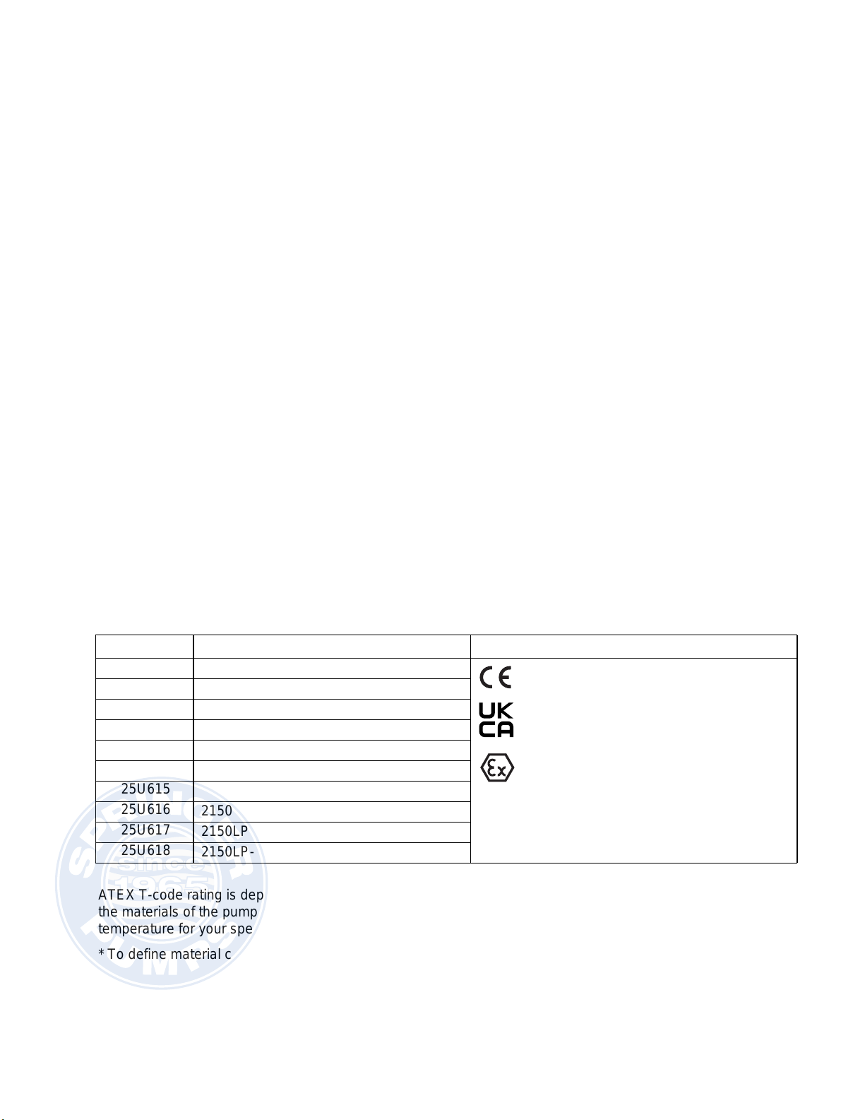
Models
Part Configuration Number* Approvals
25U609 2150LP-PA01AA1FB-BBNBN
25U610 2150LP-PA01AA1FB-BSPBN
25U611 2150LP-PA01AA1FB-BTPBN
25U612 2150LP-PA01AA1FB-BGEBN
25U613 2150LP-PA01AA1FB-BCRBN
25U614 2150LP-PA01AA2FB-BBNBN II 2 GD
Ex h IIC 66°C...82°C Gb
Ex h IIIC T82°C Db
25U615 2150LP-PA01AA2FB-BSPBN
25U616 2150LP-PA01AA2FB-BTPBN
25U617 2150LP-PA01AA2FB-BGEBN
25U618 2150LP-PA01AA2FB-BCRBN
ATEX T-code rating is dependent on the temperature of the fluid being pumped. Fluid temperature is limited by
the materials of the pump interior wetted parts. See Technical Specifications for the maximum fluid operating
temperature for your specific pump model.
* To define material codes, see Configuration Number Matrix, page 5.
Tel: 866-777-6060
Fax: 866-777-6383
Springer Pumps, LLC
Website: www.springerpumps.com
Int'l: +001 267 404 2910

Warnings
3A8693B 3
Warnings
The following warnings are for the setup, use, grounding, maintenance, and repair of this equipment. The
exclamation point symbol alerts you to a general warning and the hazard symbols refer to procedure-specific risks.
When these symbols appear in the body of this manual or on warning labels, refer back to these Warnings.
Product-specific hazard symbols and warnings not covered in this section may appear throughout the body of this
manual where applicable.
WARNING
EQUIPMENT MISUSE HAZARD
Misuse can cause death or serious injury.
• Do not operate the unit when fatigued or under the influence of drugs or alcohol.
• Do not exceed the maximum working pressure or temperature rating of the lowest rated system
component. See Technical Specifications in all equipment manuals.
• Use fluids and solvents that are compatible with equipment wetted parts. See Technical
Specifications in all equipment manuals. Read fluid and solvent manufacturer’s warnings. For
complete information about your material, request Safety Data Sheets (SDSs) from distributor or
retailer.
• Turn off all equipment and follow the Pressure Relief Procedure when equipment is not in use.
• Check equipment daily. Repair or replace worn or damaged parts immediately with genuine
manufacturer’s replacement parts only.
• Donotalter or modifyequipment. Alterations or modificationsmay void agencyapprovals and create
safety hazards.
• Make sure all equipment is rated and approved for the environment in which you are using it.
• Use equipment only for its intended purpose. Call your distributor for information.
• Route hoses and cables away from traffic areas, sharp edges, moving parts, and hot surfaces.
• Do not kink or over bend hoses or use hoses to pull equipment.
• Keep children and animals away from work area.
• Comply with all applicable safety regulations.
FIRE AND EXPLOSION HAZARD
Flammable fumes, such as solvent and paint fumes, in work area can ignite or explode. Paint or
solvent flowing through the equipment can cause static sparking. To help prevent fire and explosion:
• Use equipment only in well-ventilated area.
• Eliminate all ignition sources, such as pilot lights, cigarettes, portable electric lamps, and plastic drop
cloths (potential static sparking).
• Ground all equipment in the work area. See Grounding instructions.
• Keep work area free of debris, including solvent, rags and gasoline.
• Do not plug or unplug power cords, or turn power or light switches on or off when flammable fumes
are present.
• Use only grounded hoses.
•Stopoperation immediately if staticsparkingoccursoryoufeelashock.Donot useequipmentuntil
you identify and correct the problem.
• Keep a working fire extinguisher in the work area.
• Route exhaust away from all ignition sources. If diaphragm ruptures, fluid may be exhausted with air.
Tel: 866-777-6060
Fax: 866-777-6383
Springer Pumps, LLC
Website: www.springerpumps.com
Int'l: +001 267 404 2910

Warnings
4 3A8693B
PRESSURIZED EQUIPMENT HAZARD
Fluid from the equipment, leaks, or ruptured components can splash in the eyes or on skin and cause
serious injury.
• Follow the Pressure Relief Procedure when you stop spraying/dispensing and before cleaning,
checking, or servicing equipment.
• Tighten all fluid connections before operating the equipment.
• Check hoses, tubes, and couplings daily. Replace worn or damaged parts immediately.
PRESSURIZED ALUMINUM PARTS HAZARD
Use of fluids that are incompatible with aluminum in pressurized equipment can cause serious chemical
reaction and equipment rupture. Failure to follow this warning can result in death, serious injury, or
property damage.
• Do not use 1,1,1-trichloroethane, methylene chloride, other halogenated hydrocarbon solvents or
fluids containing such solvents.
• Do not use chlorine bleach.
• Manyotherfluidsmaycontainchemicalsthatcanreactwithaluminum.Contactyourmaterialsupplier
for compatibility.
TOXIC FLUID OR FUMES HAZARD
Toxic fluids or fumes can cause serious injury or death if splashed in the eyes or on skin, inhaled, or
swallowed.
• Read Safety Data Sheets (SDSs) to know the specific hazards of the fluids you are using.
• Route exhaust away from work area. If diaphragm ruptures, fluid may be exhausted into the air.
• Store hazardous fluid in approved containers, and dispose of it according to applicable guidelines.
BURN HAZARD
Equipment surfaces and fluid that is heated can become very hot during operation. To avoid severe
burns:
• Do not touch hot fluid or equipment.
PERSONAL PROTECTIVE EQUIPMENT
Wear appropriate protective equipment when in the work area to help prevent serious injury, including
eye injury, hearing loss, inhalation of toxic fumes, and burns. Protective equipment includes but is not
limited to:
• Protective eyewear, and hearing protection.
• Respirators, protective clothing, and gloves as recommended by the fluid and solvent manufacturer.
WARNING
Tel: 866-777-6060
Fax: 866-777-6383
Springer Pumps, LLC
Website: www.springerpumps.com
Int'l: +001 267 404 2910

Configuration Number Matrix
3A8693B 5
Configuration Number Matrix
Check the identification plate (ID) for the part number
and configuration number of your equipment. Use the
following matrix to define the components of your
equipment.
Record your equipment part number and configuration
number to assist you when ordering replacement parts:
______________________
____________________________________________
NOTE: Some combinations are not possible. See Models, page 2, or check with your local supplier.
ID
Sample Configuration Number: 2150LP-PA01AA1FB-BBNBN
2150 LP P A01A A1 FB -B BN BN
Pump
Model WettedSection
Material Drive Center Section and
Air Valve Material Manifolds Seats Checks Diaphragms Gaskets
Pump Wetted Section
Material Drive Type Center Section and Air Valve
Material Manifolds
2150 LP Large Particle P Pneumatic A01A Aluminum A1 Aluminum, NPT
A2 Aluminum, BSPT
Seat Material Checks Diaphragm Material Gaskets
FB 303 Stainless Steel
with Buna-N Seals -B Buna-N Overmolded 303
Stainless Steel Flapper BN Buna-N BN Buna-N
CR Polychloroprene
GE Geolast
TP TPE
SP Santoprene®
Tel: 866-777-6060
Fax: 866-777-6383
Springer Pumps, LLC
Website: www.springerpumps.com
Int'l: +001 267 404 2910

Typical Installation
6 3A8693B
Typical Installation
KEY:
A Air supply line
B Bleed-type master air valve (for pump) (required,
not supplied)
C Air regulator (required, not supplied)
E Master air valve (for accessories)
F Air line filter
G Flexible, conductive fluid supply line
J Fluid drain valve (required, not supplied)
K Fluid shutoff valve
L Flexible, conductive fluid outlet line
N* Air inlet port
R‡Fluid inlet port
S‡Fluid outlet port
Y Ground wire
*1/2 in. npt(f) port.
‡For pumps with connection code TN: 2-11.5 in. npt(f).
For pumps with connection code TB: 2-11 in. bspt(f).
Can be oriented to a vertical or horizontal position. See
Orientation of Fluid Inlet and Outlet Ports, page 11.
FIG. 1: Typical Installation
A
B
C
E
F
G
J
K
L
N
R
S
Y
Tel: 866-777-6060
Fax: 866-777-6383
Springer Pumps, LLC
Website: www.springerpumps.com
Int'l: +001 267 404 2910

Installation
3A8693B 7
Installation
General Information
•A typical installation is shown in FIG. 1. It is only a
guide for selecting and installing system
components. Contact your Graco distributor for
assistance in planning a system to suit your needs.
•Always use genuine Graco parts and accessories.
•Reference numbers and letters in parentheses refer
to the callouts in the figures.
Before First Use
After you unpack the equipment, and before you use it
for the first time, check and torque all external fasteners.
See Torque Sequence, page 29. After the first day of
operation, retorque the fasteners.
Check and tighten all air and fluid connections before
operating the equipment. Replace worn or damaged
parts as needed.
Grounding
Pump: Connect a ground wire and clamp (Y) as shown
in FIG. 2. To order a ground wire and clamp, order part
number 238909. Loosen the grounding screw (W). Insert
one end of a 12-gauge (1.5 mm2) or thicker ground wire
behind the grounding screw and tighten the screw
securely. Connect the clamp end of the ground wire to a
true earth ground.
02646E
Y
W
•Air and fluid lines: Use only conductive lines with a
maximum of 500 ft (150 m) combined line length to
ensure grounding continuity. Check electrical
resistance of lines. If total resistance to ground
exceeds 29 megohms, replace line immediately.
•Air compressor: Follow manufacturer’s
recommendations.
•Fluid supply container: Follow local codes and
regulations.
•Solvent pails used when flushing: Follow local
codes and regulations. Use only conductive metal
pails, placed on a grounded surface. Do not place
the pail on a nonconductive surface, such as paper
or cardboard, which interrupts grounding continuity.
NOTICE
Firmly tighten all connections to avoid air or fluid
leaks. To avoid equipment damage, do not
over-torque the fasteners on the equipment. See
Torque Sequence, page 29.
The equipment must be grounded to reduce the risk of
static sparking. Static sparking can cause fumes to
ignite or explode. Grounding provides an escape wire
for the electric current. Follow local codes and
regulations.
FIG. 2: Grounding
Tel: 866-777-6060
Fax: 866-777-6383
Springer Pumps, LLC
Website: www.springerpumps.com
Int'l: +001 267 404 2910

Installation
8 3A8693B
Mounting
Rubber Foot Mounting Kit 236452 is available to reduce
noise and vibration during operation (purchase
separately).
1. Ensure that the mounting surface is level and can
support the weight of the equipment, lines, and
accessories, as well as the stress caused during
operation.
2. Mount the equipment on a level surface and secure
the equipment to the mounting surface. For all
mountings, ensure that the equipment is bolted
directly to the mounting surface. See Dimensions,
page 31, for dimensions of the mounting holes for
your equipment.
NOTE: For ease of operation and service, mount
the equipment so the air valve cover, air inlet, and
fluid inlet and outlet ports are easily accessible.
Air Exhaust Ventilation
NOTE: The air exhaust port is 3/4 npt(f). Do not restrict
the air exhaust port. Excessive exhaust restriction can
reduce equipment performance.
To provide a remote exhaust:
1. Remove the muffler (P) from the air exhaust port.
See FIG. 3.
2. Install a conductive, grounded air exhaust line (T)
and connect the muffler (P) to the other end of the
line. The minimum size for the air exhaust line is
3/4 in. (19 mm) inner-diameter. If a line longer than
15 ft (4.57 m) is required, use a larger diameter line.
Avoid sharp bends or kinks in the line.
3. Place a conductive, grounded container (U) at the
end of the air exhaust line to catch fluid in case of a
diaphragm rupture. See FIG. 3.
The equipment is heavy (see Technical
Specifications for specific weights). If the equipment
must be moved, follow the Pressure Relief
Procedure, page 12, and have two people lift the
equipment by grasping the outlet manifold securely,
or use appropriate lifting equipment to lift by the outlet
manifold. Never have one person move or lift the
equipment.
Be sure the system is properly ventilated for your type
of installation. Exhaust must be vented to a safe
place, away from people, animals, food handling
areas, and all sources of ignition when pumping
flammable or hazardous fluids. Diaphragm rupture
can cause the fluid being pumped to exhaust with the
air. Place a grounded container at the end of the air
exhaust line to catch the fluid. See FIG. 3.
FIG. 3: Air Exhaust Ventilation
KEY:
A Air supply line
B Bleed-type master air valve (for pump)
(required, not supplied)
C Air regulator (required, not supplied)
D Air line quick disconnect
E Master air valve (for accessories)
F Air line filter
P Muffler
T Conductive air exhaust line
U Conductive container for air exhaust
A
B
C
D
E
F
P
T
U
Tel: 866-777-6060
Fax: 866-777-6383
Springer Pumps, LLC
Website: www.springerpumps.com
Int'l: +001 267 404 2910

Installation
3A8693B 9
Accessories
Install the following accessories in the order shown in
FIG. 1, using adapters as necessary.
Air Line
•Bleed-type master air valve (B): required in your
system to relieve air trapped between it and the air
motor when the valve is closed.
Be sure the valve is easily accessible from the
equipment and located downstream from the air
regulator.
•Air regulator (C): to control pump speed and fluid
outlet pressure. Locate it close to the equipment.
•Air line filter (F): removes harmful dirt and moisture
from compressed air supply.
•Master bleed-type air valve (E): isolates air line
accessories for servicing. Locate upstream from all
other air line accessories.
1. Install the air line accessories as shown in FIG. 1.
Verify that the air line supplying the accessories is
grounded.
2. Install a conductive, flexible air line (A) between the
accessories and the 3/4 npt(f) air inlet (N). Use a
minimum 1/2 in. (13 mm) inner-diameter air line.
Fluid Supply and Outlet Lines
•Fluid drain valve (J): required in your system,
relieves fluid pressure in the fluid line.
•Fluid pressure relief valve (V): relieves fluid
pressure in the fluid line. See FIG. 5.
•Fluid shutoff valve (K): shuts off fluid flow.
1. Install flexible, conductive fluid lines (G and L).
2. Install a fluid drain valve (J) in the fluid outlet line (L)
close to the fluid outlet. See FIG. 1.
3. Install a fluid shutoff valve (K) in the fluid outlet line
(L) downstream from the fluid drain valve (J).
4. If needed, install a fluid pressure relief valve (V).
See Fluid Pressure Relief Valve, page 11.
NOTE: For best results, always install the pump as
close as possible to the material source. See the
Technical Specifications, page 32, for maximum
suction lift (wet and dry).
A bleed-type master air valve (B) is required in the
system to relieve air trapped between this valve and
the equipment. Trapped air can cause the equipment
to cycle unexpectedly, which could result in serious
injury, including splashing in the eyes or on the skin.
See FIG. 1.
A fluid drain valve (J) is required to relieve pressure in
the fluid outlet line. The drain valve reduces the risk of
serious injury, including splashing in the eyes or on
the skin, when relieving pressure.
NOTICE
The equipment can be damaged if flexible fluid lines
are not used. If hard-plumbed fluid lines are used in
the system, use a short length of flexible, conductive
fluid line to connect to the equipment.
Tel: 866-777-6060
Fax: 866-777-6383
Springer Pumps, LLC
Website: www.springerpumps.com
Int'l: +001 267 404 2910

Installation
10 3A8693B
Tips to Reduce Cavitation
Cavitation in a diaphragm pump is the formation and
collapse of bubbles in the pumped liquid. Frequent or
excessive cavitation can cause serious damage,
including pitting and early wear of fluid chambers,
flappers, and seats. It may result in reduced efficiency of
the pump. Cavitation damage and reduced efficiency
both result in increased operating costs.
Cavitation depends on the vapor pressure of the
pumped liquid, the system suction pressure, and the
velocity pressure. It can be reduced by changing any of
these factors.
1. Reduce vapor pressure: Decrease the temperature
of the pumped liquid.
2. Increase suction pressure:
a. Lower the installed position of the pump relative
to the liquid level in the supply.
b. Reduce the friction length of the suction lines.
Remember that fittings add friction length to the
lines. Reduce the number of fittings to reduce
the friction length.
c. Increase the diameter of the suction lines.
d. Ensure the inlet fluid pressure does not exceed
25% of the outlet working pressure.
3. Reduce liquid velocity: Slow the cyclic rate of the
pump.
Pumped liquid viscosity is also very important but
normally is controlled by factors that are process
dependent and cannot be changed to reduce cavitation.
Viscous liquids are more difficult to pump and more
prone to cavitation.
Graco recommends taking all of the above factors into
account in system design. To maintain pump efficiency,
supply only enough air to the pump to achieve the
required flow.
Graco distributors can supply site-specific suggestions
to improve pump performance and reduce operating
costs.
Tel: 866-777-6060
Fax: 866-777-6383
Springer Pumps, LLC
Website: www.springerpumps.com
Int'l: +001 267 404 2910

Installation
3A8693B 11
Orientation of Fluid Inlet and
Outlet Ports
The fluid port of the center manifold can be rotated to
either a vertical or horizontal position.
To change the fluid port orientation of the center
manifold (113):
1. Remove the manifold screws (120).
2. Rotate the center manifold (113) to the applicable
vertical or horizontal position.
3. Install the manifold screws (120) and torque to 50–
60 in-lb (5.65–6.78 N•m). See Torque Sequence,
page 29.
KEY:
Fluid Pressure Relief Valve
Fluid Pressure Relief Valve 112119 (stainless steel) is
available (purchase separately).
KEY:
R Fluid inlet port
S Fluid outlet port
V Pressure relief valve
Install valve between fluid inlet and outlet ports.
Connect fluid inlet line here.
Connect fluid outlet line here.
101 Fluid covers
120 Screw
113 Center manifold
FIG. 4: Fluid Inlet and Outlet Port Orientation
101
101
113
113
Apply medium-strength (blue) thread locker to the
threads. Torque to 50–60 in-lb (5.65–6.78 N•m). See
Torque Sequence, page 29.
1
1
1
1
1
120
120
120
120
Some systems may require installation of a pressure
relief valve (V) at the pump outlet to prevent
overpressurization and rupture of the pump or hose.
Thermal expansion of fluid in the outlet line can cause
overpressurization. Thermal expansion can occur
when using long fluid lines exposed to sunlight or
ambient heat, or when pumping from a cool to a warm
area (for example, from an underground tank).
Overpressurization also can occur if the pump is used
to feed fluid to a piston pump, and the intake valve of
the piston pump does not close, causing fluid to back
up in the outlet line.
The pressure relief valve reduces the risk of serious
injury, including splashing in the eyes or on the skin.
FIG. 5: Fluid Pressure Relief Valve
1
2
3
R
S
V
1
2
3
Tel: 866-777-6060
Fax: 866-777-6383
Springer Pumps, LLC
Website: www.springerpumps.com
Int'l: +001 267 404 2910

Operation
12 3A8693B
Operation
Pressure Relief Procedure
1. Close the bleed-type master air valve (B) to shut off
the air to the equipment.
2. Open outbound fluid valve to relieve fluid pressure
from the equipment.
a. For simple transfer applications, open either
the fluid shutoff valve (K) or the fluid drain
valve (J).
b. For circulating applications, ensure that the
fluid shutoff valve (K) is closed and open the fluid
drain valve (J).
Flush Before Using Equipment
NOTE: The equipment was tested with water. If water
could contaminate your fluid, flush the equipment with a
compatible solvent before using the equipment.
Properly flush the equipment before use. Perform Start
and Adjust the Equipment, page 12, and Flushing
and Storage, page 13.
Start and Adjust the Equipment
1. Confirm that the equipment is properly grounded.
See Grounding, page 7.
2. Check and tighten all fasteners, air connections, and
fluid connections before operating the equipment.
Replace worn or damaged parts as needed.
3. Connect a flexible, conductive fluid supply line (G)
from the fluid to be pumped to the fluid inlet port (R).
4. Connect the flexible, conductive fluid outlet line (L) to
the fluid outlet port (S) and route the line to the end
container.
5. Close the fluid drain valve (J).
6. Turn the air regulator (C) to the lowest air pressure
setting and open the bleed-type master air valve (B).
7. If the fluid outlet line (L) has a dispensing device,
hold it open while continuing with the following step.
8. To prime the pump, slowly increase air pressure with
the air regulator (C) until pump starts to cycle. Do not
exceed the maximum operating air pressure listed in
the Technical Specifications, page 32. Allow the
pump to cycle slowly until all air is pushed out of the
fluid lines and fluid exits the fluid outlet line (L).
Equipment Shutdown
At the end of each work shift, perform the Pressure
Relief Procedure, page 12.
Flush the equipment if necessary. See Flushing and
Storage, page 13.
Follow the Pressure Relief Procedure
whenever you see this symbol.
This equipment stays pressurized until pressure is
manually relieved. To help prevent serious injury from
pressurized fluid, such as splashing fluid, follow the
Pressure Relief Procedure when you stop
dispensing and before cleaning, checking, or
servicing the equipment.
NOTICE
Firmly tighten all fasteners and connections to avoid
air or fluid leaks. To avoid equipment damage, do not
over-torque the fasteners on the equipment. See
Torque Sequence, page 29.
Tel: 866-777-6060
Fax: 866-777-6383
Springer Pumps, LLC
Website: www.springerpumps.com
Int'l: +001 267 404 2910

Maintenance
3A8693B 13
Maintenance
Before Each Use
Before each use, check and torque all fasteners before
operating the equipment. See Torque Sequence, page
29. Replace worn or damaged parts as needed.
NOTE: Be sure to use a compatible liquid thread sealant
on all replaced male threads.
Check and tighten all air and fluid connections before
operating the equipment. Replace worn or damaged
parts as needed.
Lubrication
The equipment is lubricated at the factory. It is designed
to require no further lubrication for the life of the
equipment. There is no need to add an inline lubricator
under normal operating conditions.
The air valve is designed to operate unlubricated. If
lubrication is desired, every 500 hours of operation (or
monthly) remove the line from the equipment air inlet
and add two drops of machine oil to the air inlet.
Flushing and Storage
•Flush before changing fluid materials, before fluid
can dry or freeze in the equipment, at the end of the
day, before storing, and before repairing equipment.
•Flush at the lowest pressure possible. Check and
tighten all fasteners and fluid connections. Replace
worn or damaged parts as needed.
•Flush with a solvent that is compatible with the fluid
being dispensed and the equipment wetted parts.
•Flushing schedule will vary based on particular uses.
•Always cycle the equipment during the entire
flushing process.
•Always perform the Pressure Relief Procedure,
page 12, and flush the equipment before storing it
for any length of time.
1. Perform the Pressure Relief Procedure, page 12.
2. Insert the suction end of the supply line (G) into a
compatible solvent.
3. Open the air regulator (C) to supply low pressure air
to the equipment.
4. Run the equipment for enough time to thoroughly
clean the equipment and lines.
5. Close the air regulator (C).
6. Remove the suction end of the supply line (G) from
the compatible solvent and drain the equipment.
Recycling and Disposal
End of Product Life
At the end of the product’s useful life, dismantle and
recycle it in a responsible manner.
• Perform the Pressure Relief Procedure, page 12.
• Drain and dispose of fluids according to applicable
regulations. Refer to the material manufacturer’s
Safety Data Sheet.
• Deliver remaining product to a recycling facility.
NOTICE
Firmly tighten all fasteners and connections to avoid
air or fluid leaks. To avoid equipment damage, do not
over-torque the fasteners on the equipment. See
Torque Sequence, page 29.
NOTICE
Do not over-lubricate the equipment. Lubricant is
exhausted through the muffler and could contaminate
your fluid supply or other equipment. Excessive
lubrication can also cause the equipment to
malfunction.
To avoid fire and explosion, always ground equipment
and waste container. To avoid static sparking and
injury from splashing, always flush at the lowest
possible pressure.
Tel: 866-777-6060
Fax: 866-777-6383
Springer Pumps, LLC
Website: www.springerpumps.com
Int'l: +001 267 404 2910

Troubleshooting
14 3A8693B
Troubleshooting
1. Follow Pressure Relief Procedure, page 12,
before checking or repairing the equipment.
2. Check all possible problems and causes before
disassembling equipment.
Problem Cause Solution
Equipment cycles at stall or
fails to hold pressure at
stall.
Worn check valve flappers (116), seats (115)
or gaskets (112, 114). Replace. See page 16.
Equipment will not cycle, or
cycles once and stops. Air valve is stuck or dirty. Disassemble and clean air valve. See
page 21. Use filtered air.
Check valve flapper (116) is stuck. Replace flapper and seat. See
page 16.
Check valve flapper (116) is stuck due to
overpressurization. Install Pressure Relief Valve. See
page 11.
Dispensing valve clogged. Relieve pressure and clear valve.
Equipment cycles but will
not prime or no flow. Excessive suction lift. Ensure the suction lift does not exceed
the maximum listed in Technical
Specifications, page 32. To aid with
priming, fill the chambers with liquid.
Equipment operates
erratically. Clogged suction line. Inspect; clear.
Sticky or leaking check valve flapper (116). Clean or replace. See page 16.
Diaphragm ruptured. Replace. See page 18.
Restricted exhaust. Remove restriction.
Air bubbles in fluid. Supply line is loose. Tighten.
Diaphragm ruptured. Replace. See page 18.
Loose inlet manifold components, damaged
gasket (121) between manifold components,
or damaged check valve gaskets (112, 114).
Tighten manifold bolts (120) or replace
seats (115) or gaskets (112, 114, or
121). See page 16.
Loose diaphragm shaft bolt (107). Tighten or replace. See page 18.
Damaged o-ring (108). Replace. See page 18.
Fluid in exhaust air. Diaphragm ruptured. Replace. See page 18.
Loose diaphragm shaft bolt (107). Tighten or replace. See page 18.
Damaged o-ring (108). Replace. See page 18.
Equipment exhausts
excessive air at stall. Worn air valve block (7), o-ring (6), plate (8),
pilot block (18), u-cups (10), or pilot pin o-rings
(17).
Repair or replace. See page 21.
Worn shaft seals (402). Replace. See page 18.
Tel: 866-777-6060
Fax: 866-777-6383
Springer Pumps, LLC
Website: www.springerpumps.com
Int'l: +001 267 404 2910

Troubleshooting
3A8693B 15
Equipment leaks air
externally. Air valve cover (2) or air valve cover screws
(3) are loose. Tighten screws. See page 21.
Air valve gasket (4) or air cover gasket (22) is
damaged. Inspect; replace. See pages 18 to 21.
Air cover screws (3) are loose. Tighten screws. See page 21.
Equipment leaks fluid
externally from flapper
check valves.
Over-torqued center manifold bolts (120),
causing the joint between the fluid cover (101)
and manifolds (102, 103) to separate.
Or loose joint between manifolds (102, 103)
and fluid cover (101).
Loosen manifold center bolts (120).
Tighten manifold bolts (120), see
Torque Sequence, page 29.
Retorque manifold center bolts (120).
See Torque Sequence, page 29. Do
not overtighten.
Damaged gaskets (112, 114). Replace gaskets (112, 114), see page
16.
Problem Cause Solution
Tel: 866-777-6060
Fax: 866-777-6383
Springer Pumps, LLC
Website: www.springerpumps.com
Int'l: +001 267 404 2910

Repair
16 3A8693B
Repair
Repair kits available to purchase separately. Use all parts in the kits for best results. See Parts, starting on page 25.
Check Valve Repair
Tools Required:
• Torque wrench
• 10 mm socket wrench
• 15 mm socket wrench
See Kits and Accessories, page 28, for available
repair kits. Service the check valves as follows.
See FIG. 6.
Disassemble Check Valves
1. Perform the Pressure Relief Procedure, page 12.
2. Disconnect all air and fluid lines from the equipment.
3. Remove screws (120) from manifolds (102, 103).
Remove manifolds from fluid covers (101).
NOTE: Use care while removing manifolds to avoid
damage to check valve components.
4. Remove all check valve components and gaskets
(121).
NOTE: Pay attention to the orientation of the check
valve components for reassembly.
5. Clean and inspect all parts for wear or damage.
Replace as needed.
NOTE: To ensure proper seating, always replace all
seat and check valve components when performing
check valve repairs.
Reassemble Check Valves
1. Install all check valve components in the correct
orientation. See FIG. 6.
NOTE: Ensure that the check valves and seating
areas are clean.
NOTE: Install the flapper valves with the solid
rubber side facing toward the seat.
2. Install gaskets (121).
NOTE: Grease both surfaces of the gasket (121)
before reassembling manifolds (102, 103).
3. Align manifolds (102, 103) with fluid covers (101).
4. Insert screws (120) and torque. See Torque
Sequence, page 29.
5. Reconnect air and fluid lines to equipment.
Tel: 866-777-6060
Fax: 866-777-6383
Springer Pumps, LLC
Website: www.springerpumps.com
Int'l: +001 267 404 2910

Repair
3A8693B 17
FIG. 6: Check Valve Section
102
103
Fluid outlet shown
Fluid inlet shown
101
101
1
1
120
120
120
120
Apply medium-strength (blue) thread locker to the
threads. Torque to 190–220 in-lb (21.5–24.9 N•m).
See Torque Sequence, page 29.
1
119
118
117
116
112
115
114
114
115
112
116
117
118
119
121
121
Seat and
check valve
components
Seat and
check valve
components
2
3
2
2
3
Apply medium-strength (blue) thread locker to the
threads. Torque to 120–130 in-lb (13–14 N•m). See
Torque Sequence, page 29.
Apply medium-strength (blue) thread locker to the
threads. Torque to 20–25 in-lb (2.26–2.82 N•m).
3
Grease.
4
4
4
Tel: 866-777-6060
Fax: 866-777-6383
Springer Pumps, LLC
Website: www.springerpumps.com
Int'l: +001 267 404 2910

Repair
18 3A8693B
Diaphragm Repair
Tools Required:
• Torque wrench
• 10 mm socket wrench
• 15 mm socket wrench
• 19 mm open-end wrench
• O-ring pick
• Lithium-base grease, part no. 111920 (Lubriplate
630AA or equivalent)
Service the diaphragms as follows.
See F
IG. 7–FIG. 9.
Disassemble Diaphragms
1. Perform the Pressure Relief Procedure, page 12.
2. Disconnect all air and fluid lines from the equipment.
3. Perform Disassemble Check Valves, page 16.
4. Remove screws (106, 120) from fluid covers (101).
Remove fluid covers from air covers (23).
5. Use an applicable wrench to loosen the diaphragm
shaft bolts (107). Do not remove bolt.
6. Remove one diaphragm assembly (401). See FIG.
9.
7. Remove the other diaphragm assembly (401) with
the shaft (24).
8. Disassemble the diaphragm plates (104, 105),
diaphragms (401), packing o-rings (108), and bolt
(107).
9. Clean and inspect all parts for wear or damage.
Replace as needed.
Reassemble Diaphragms
1. Assemble the diaphragm plates (104, 105), packing
o-ring (108), and diaphragm (401) onto the
diaphragm shaft bolt (107). See FIG. 9.
NOTE: Install diaphragms (401) with the side
marked AIR SIDE facing toward the center housing
(1). See FIG. 8.
2. Screw the diaphragm assembly onto one side of the
shaft (24). Torque to 28–33 in-lb (3.2–3.7 Nm).
3. Grease the length of the shaft (24) and slide through
the center housing (1).
4. Repeat steps 1–2 for the other diaphragm
assembly.
5. Apply medium-strength (blue) thread locker to the
threads of the fluid cover screws (106, 120).
6. Align fluid covers (101) with center housing (1) and
insert fluid cover screws (106, 120). Torque to 40–
45 ft-lb (54.2–61 N•m) at 100 rpm maximum. See
Torque Sequence, page 29.
7. Perform Reassemble Check Valves, page 16.
8. Reconnect air and fluid lines to equipment.
NOTICE
After reassembly, allow the thread locker to cure for
12 hours, or per manufacturer’s instructions, prior to
operating the equipment. Damage to the equipment
will occur if the diaphragm shaft bolt loosens.
Tel: 866-777-6060
Fax: 866-777-6383
Springer Pumps, LLC
Website: www.springerpumps.com
Int'l: +001 267 404 2910

Repair
3A8693B 19
FIG. 7: Diaphragm Section
Apply medium-strength (blue) thread locker to the
threads. Torque to 190–220 in-lb (21–25 N•m).
See Torque Sequence, page 29.
1
2Circular outlet hole must be at
the base of the equipment.
1
1
1
106
1
23
2
2
2
120
101
106
120
101
107
Tel: 866-777-6060
Fax: 866-777-6383
Springer Pumps, LLC
Website: www.springerpumps.com
Int'l: +001 267 404 2910

Repair
20 3A8693B
FIG. 8: Diaphragm Section, Cutaway Views
FIG. 9: Diaphragm Section, Shaft Assembly
03982A03981A
Cutaway View, with diaphragms Cutaway View, diaphragms removed
1
2
105
5
107
3
401
7104
424 19 1
402
1
Lips face out of housing (1).
Rounded side faces diaphragm (401).
AIR SIDE must face center housing (1).
Grease.
Apply medium-strength (blue) thread locker. Torque to 40–45 ft-lb (54.2–61 N•m) at 100 rpm maximum.
Recessed side faces diaphragm (401).
1
2
3
4
5
7
1
424
3
401 3
401
424
7104
2
105
5
107
108
Tel: 866-777-6060
Fax: 866-777-6383
Springer Pumps, LLC
Website: www.springerpumps.com
Int'l: +001 267 404 2910
Table of contents
Popular Water Pump manuals by other brands

DAB
DAB NKVE MCE Series Instruction for installation and maintenance

DAB PUMPS
DAB PUMPS S4 Instruction for installation and maintenance

DAB
DAB K 36/200 Instruction for installation and maintenance

Zoeller
Zoeller Qwik Jon Ultima 204 installation instructions

Espa
Espa VX V 1100AS instruction manual

Calpeda
Calpeda NR Original operating instructions

Masterflex
Masterflex MASTERSENSE MFLX07526-10 operating manual

salmson
salmson Rocsan SDL Series Installation and starting instructions

Graco
Graco Dura-Flo 1800 Series Instructions-parts list

Otto Bock
Otto Bock 4R220-1 Instructions for use

Zuwa
Zuwa UNISTAR 2000-A operating instructions

salmson
salmson NSB04-15 Installation and starting instructions