- 7 -
● Voltage and Current Hazards
It is very dangerous to turn on the power without prior notice to workers
maintaining the system. Never turn on the power unexpectedly. Careless
supply of power will injure or kill workers due to operating automation
or electric shock. Give a warning to other workers, and do not permit
outsiders to turn on the power.
The control system of this system operates on 380VAC(varies with
specification). The energized part and the current-carrying part are
sealed with the door panel under the normal operation, and the
operator is not exposed to voltage and current hazards. It is only when
the system is operated or maintained keeping the door panel open that
the operator is exposed to such hazards.
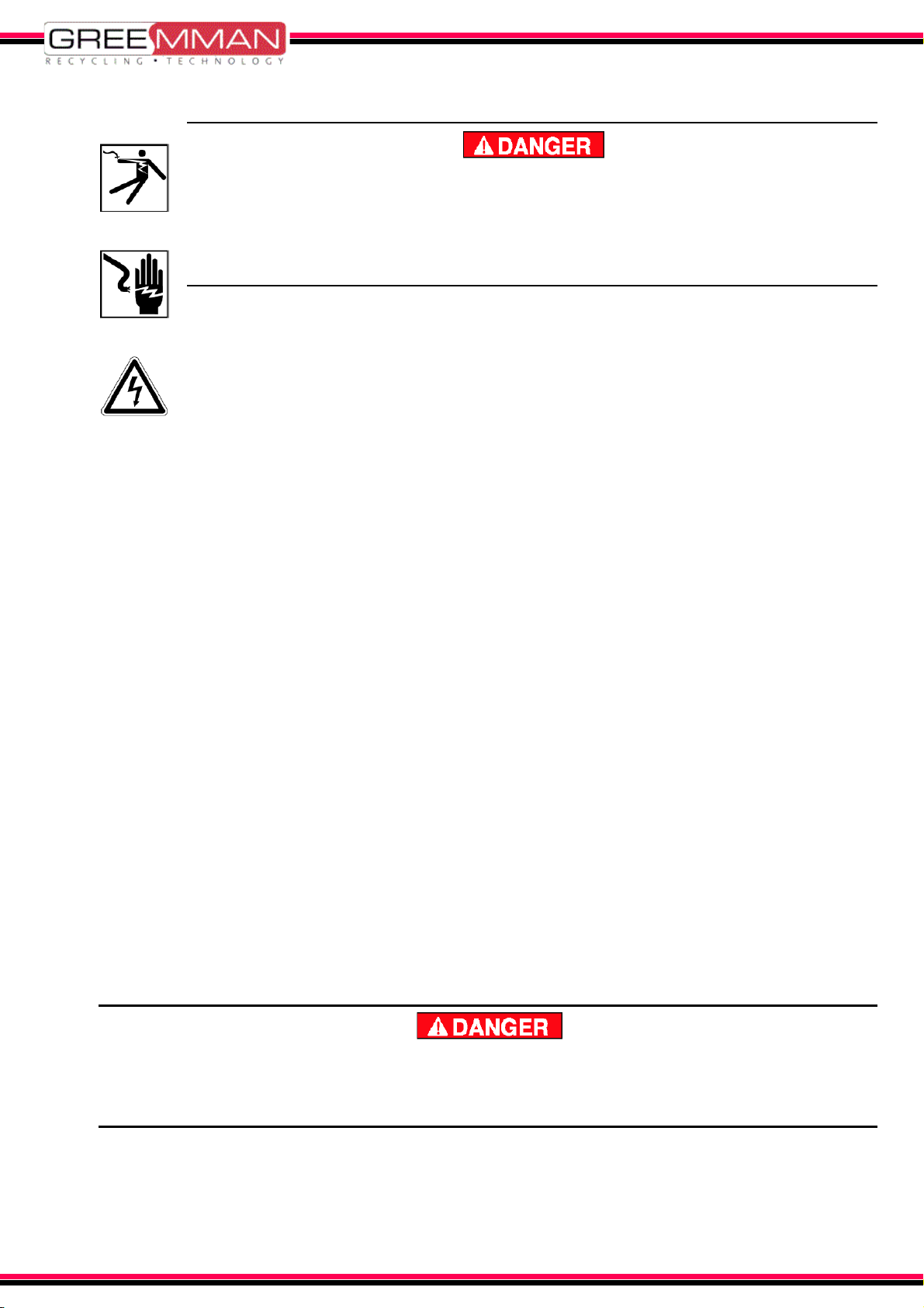
● Danger of Electric Shock
When you touch energized parts or current carrying parts will cause electric shock or
bring serious injury or death to the operator due to heat of short-circuit or scattered
objects.
• When you maintain the section supposed to be energized and carry current, make
sure that the system power is turned off. Besides that, check voltage doesn’t load
the section with voltage tester before starting a maintenance work.
• If a worker wearing metal or conductive ornaments and precious metals (ring, wrist
watch, bracelet, etc.) operates or maintain the system, such ornaments may contact
any energized parts, he or she will be damaged by electric accidents. Be sure to
remove ornaments and precious metals when operating or maintaining the system.
● Danger of Short circuit
When the earth leakage breaker is actuated and the breaker is set to OFF, or when
the fuse is found to be blown, the system may have a short-circuit.
• Turn off the power and investigate the cause, or the breaker will not only actuate
again but also electric shock will occur due to leakage.
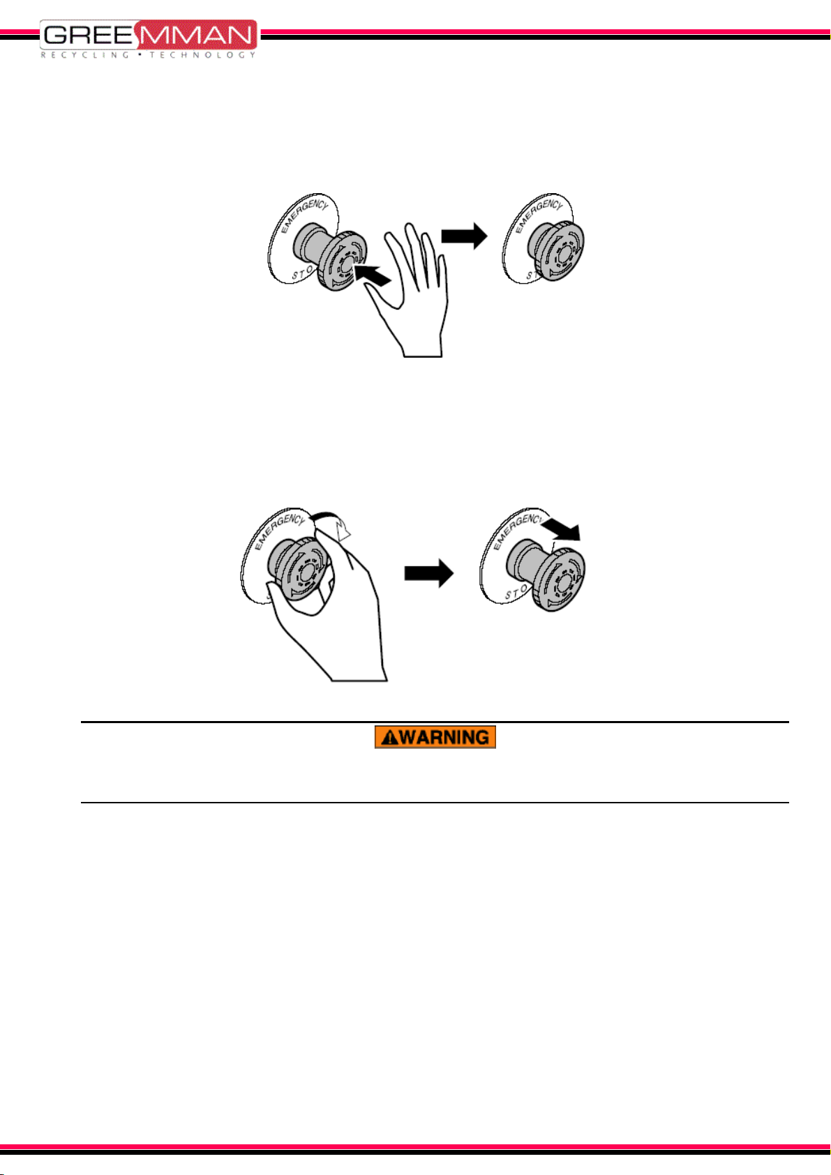
● Emergency Off Switch (EMO Switch)
In case of an emergency stop with the EMO switch and interlock switch, the
breaker inside the system is shut off. Unless the power on the factory is turned
off, the primary side of the breaker has been still energized. So, do not touch
terminals.
The system is fitted with an Emergency Off (EMO, Interlock) Switch. Pressing the
switch shuts off the power to the system. Before operation or maintenance work,
be sure to check the location of the EMO switch and to understand how to use it.
Check operation of the EMO switch at constant intervals.