9
3. Receiver Installation and UTP Connection:
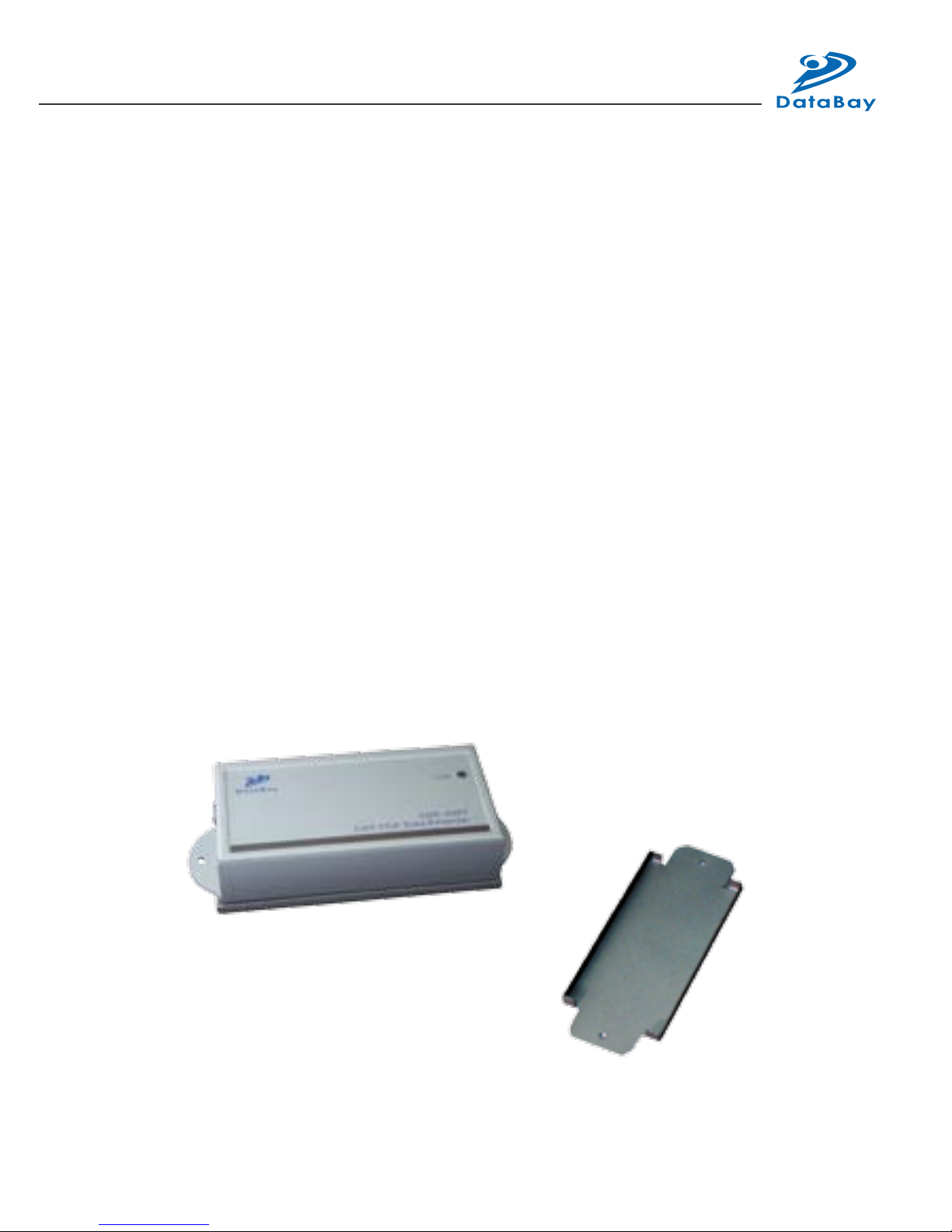
(1) Site Selection: Please place Receiver in an appropriate place and
have the UTP cable (Cat5/5e/6 cable and Cat5e is preferred) settled
for later connection. You can use magnetic pad to attach the unit
on a metal plane (Ex PC / Server enclosure) or use attachable rack
mounting kit to x the unit on selected area by screw or nail.
(2) UTP Cable Selection: For best VGA performance, you can refer
to following type of UTP Cat5 cable - Belden DataTwist 350 UTP -
#1700A – Solid, Belden DataTwist 350 patch - #1752A – Stranded, or
Belden DataTwist Category 5e – 1583A – Paired cable.
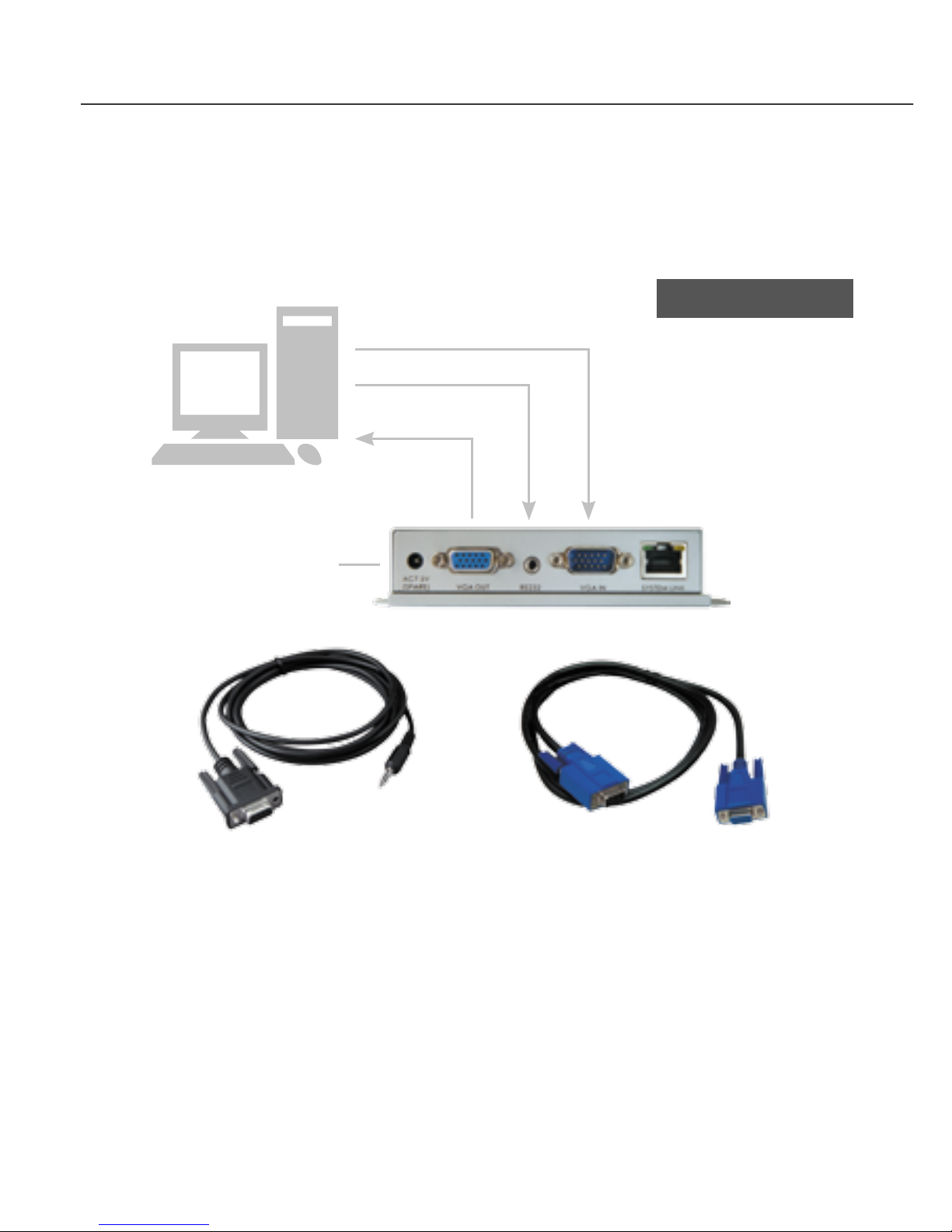
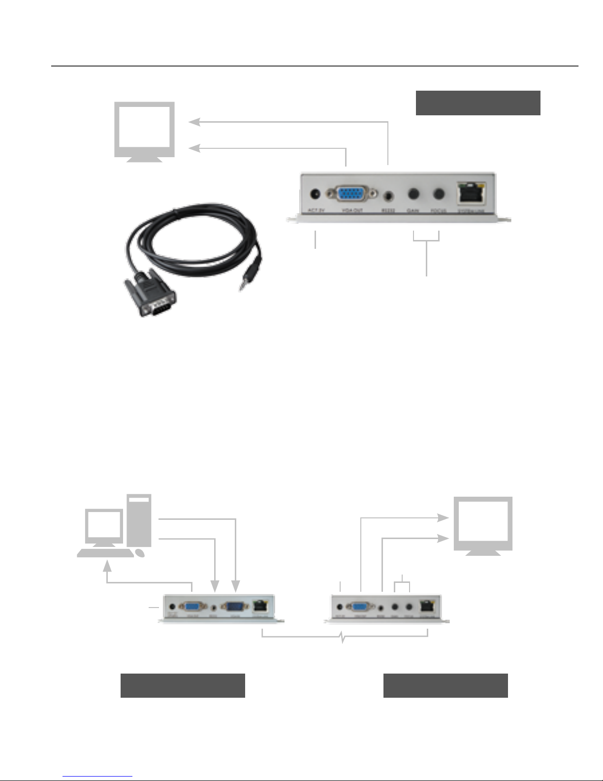
(3) Power On: Plug power adapter to the Receiver and connect Touch
Screen’s VGA and Serial connection to Receiver. For most of the
Touch Screen (Serial Connection), it will be required to take the power
from PS/2 to activate the Tx/Rx communication, so the Receiver has
built in a PS/2 port to provide a DC5V power for Touch Screen. The
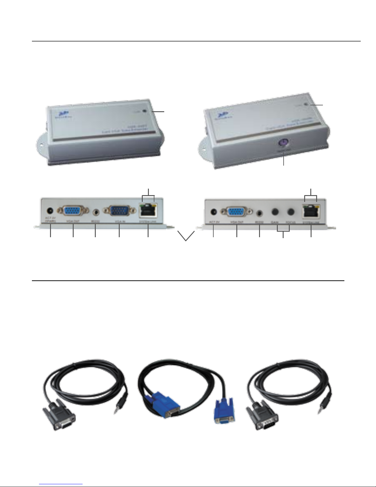
LEDs of the STATUS will stay on Blue to indicate power on status
and the RJ-45 LEDs will blink to indicate the unconnected status of
Cat5/5e/6 cable.
The PS/2
Connector is Used
to Provide a DC5V
Power for Touch
ScreenMounting Kit
Unit attached with Rack Mounting Kit and the Rack Mounting Kit
11
4 3
56
5V