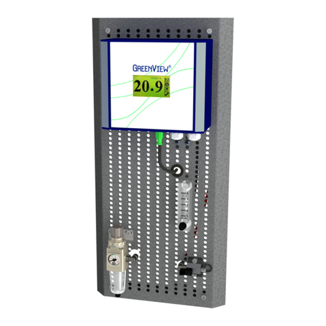
GREEN INSTRUMENTS G3600 User manual

G3600/3601
Inert Gas Sampling Boards
Manual
Document ID number.: 01597

2

G3600/G3601 Inert Gas Sampling Boards
Ver.2.3 –Revision April 2022 3
Content
1INTRODUCTION..................................................................................................5
1.1 ABOUT THIS MANUAL.........................................................................................................5
1.2 INQUIRIES AND FEEDBACK..................................................................................................6
2SPECIFICATIONS ...............................................................................................7
3INSTALLATION...................................................................................................8
3.1 CONTROLAT DELIVERY......................................................................................................8
3.2 WHERE TO INSTALL THE SYSTEM........................................................................................8
3.3 SAFETY ASPECTS..............................................................................................................8
3.4 SINGLE BOARD .................................................................................................................9
3.4.1 Mounting Panel..................................................................................................9
3.4.2 Sample Gas Connection....................................................................................9
3.4.3 Calibration Gas Connection.............................................................................10
3.4.4 Vent Line Connection ......................................................................................12
3.4.5 Analyzer and Electrical Connection.................................................................12
3.4.6 Digital Flow Switch (Optional) .........................................................................12
3.5 DOUBLE SAMPLING BOARD..............................................................................................12
3.6 RETROFITTING OF EXTENSION BOARD..............................................................................17
4COMMISSIONING .............................................................................................19
4.1 INSTALLATION CHECKS OF THE SAMPLING BOARD.............................................................19
4.2 COMMISSIONING OF THE ANALYZER..................................................................................19
4.3 START OF THE SYSTEM....................................................................................................19
5ROUTINE MAINTENANCE..................................................................................21
5.1 SAMPLING SYSTEM..........................................................................................................21
5.2 FILTER AND BUBBLE GLASS..............................................................................................21
5.3 ANALYZER.......................................................................................................................22
5.4 SENSOR .........................................................................................................................22
6SPARE PARTS.................................................................................................23
Content
4
TABLE OF FIGURES
FIGURE 3-1: PIPINGAND INSTRUMENTATION DIAGRAM -SINGLE SAMPLING BOARD.............................. 10
FIGURE 3-2: IGOASYSTEM –SINGLE SAMPLING BOARD................................................................... 11
FIGURE 3-3: IGOASYSTEM -DOUBLE SAMPLING BOARD.................................................................. 13
FIGURE 3-4: PIPINGAND INSTRUMENTATION DIAGRAM –DOUBLE SAMPLING BOARD............................14
FIGURE 3-5: ELECTRICAL CONNECTIONS OF THE SELECTOR BOX G3505...........................................15
FIGURE 3-6: ELECTRICAL CONNECTIONS OF THE SELECTOR BOX G36...............................................16

G3600/G3601 Inert Gas Sampling Boards
Ver.2.3 –Revision April 2022 5
1Introduction
1.1 About this Manual
This manual contains data and instructions for the installation, operation, and mainte-
nance of Green Instruments' inert gas sampling boards:
•G3600 IGOAS single board without flow alarm
•G3601 IGOAS double board without flow alarm
•G3602 IGOAS single board with flow alarm
•G3603 IGOAS double board with flow alarm
•G3609 IGOAS extension board (extension to G3600 and G3602)
Other system may be added at a later stage.
The sampling boards can be combined with the G36aOxygen Analyzer or the G36p Oxy-
gen Analyzer (panel mounted). One sampling board and one analyzer forms a complete
inert gas oxygen analyzing system, hereafter named an IGOASystem.
The instructions for installation, operation, and maintenance of the analyzers are provid-
ed in separate manuals:
•the G36aOxygenAnalyzer manual (p#01245)
•the G36pOxygenAnalyzer manual (p#01381)
Please read both this manual as well as the relevant oxygen analyzer manual carefully in
their entirety. The instructions have been made in general terms and do not take into con-
sideration the existing equipment of the inert gas system and its installation.
As such, the manual is designed for the standard Green Instruments IGOA System. Virtu-
ally all systems are fitted with a G36a Oxygen Analyzer. Therefore, this manual focuses
on the installation, operation, and maintenance of an IGOA System fitted with the G36a
Oxygen Analyzer.
This manual does not describe all possible situations but only the most common and
known situations. It cannot replace the necessary education and training of the personnel.
Should situations not described in the manual occur, which cannot be solved in accord-
ance with normal known practice and good workmanship, the operator should contact
Green Instruments for instructions.

Introduction
6
Green Instruments A/S reserves the right to minor alterations and improvements owing to
developments without being obliged to enter the corresponding changes in this manual.
Green Instruments A/S reserves the copyright of this manual. Without prior written per-
mission of Green Instruments A/S, the manual may not be copied and given to unauthor-
ized people.
1.2 Inquiries and Feedback
All claims and inquiries for spares shall be addressed to Green Instruments A/S or our
distributors.
In all correspondence or when ordering spare parts, please carefully state the equipment
type and serial number, which you can find on the label on the back of the G36p Oxygen
Analyzer or on the right side of the G36a Oxygen Analyzer.
Green Instruments A/S appreciates all feedback and suggestions for improvement. If you
have any questions or find any errors in the manual, you are welcome to contact us at the
following address:
Green InstrumentsA/S
Erhvervsparken 29
DK-9700 Brønderslev, Denmark
Phone: +45 9645 4500
Fax: +45 9645 4501
Web: www.greeninstruments.com

G3600/G3601 Inert Gas Sampling Boards
Ver.2.3 –Revision April 2022 7
2Specifications
Sampling Board for Inert Gas Application
Sample inlet pressure & flow
0.05 to 1 bar –2 to 8 l/min
Sample inlet temperature
0°C to 70°C
Sample manifold
3 ports –1/8” BSP connection
Span gas reduction regulator
Max. 10 bar –1/8” BSP connection
Zero gas reduction regulator
Max. 10 bar –1/8” BSP connection
Sample selector valve
5-way and 4-position switching valve SS 316
Test gas selector valve
3-way and 2-position switching valve SS 316
Inert gas single sampling
board
Dimensions: 60 × 50 × 14 cm (H × W × D)
Weight: Approx. 12 kg without water & packaging
Inert gas double sampling
board
Dimensions: 61 × 79 × 14 cm (H × W × D)
Weight: Approx. 20 kg without water & packaging
Analyzer
See details in chapter 2 in the oxygen analyzer manual.
Optional Equipment
Digital flow switch
0.2–10 l/min, 1 analog output 4–20 mA & 1 NPN out-
put, display with LED type 3 digits, 1 alarm set point
with the NPN output
Remote digital display
22…250 VAC/DC with 2 configurable alarm relays
Ambient temperature: –20°C to 60°C
Panel cut-out: 44.5 × 91.5 mm
Other optional equipment
Pre-filter for sample gas
Signal amplifier for logarithmic output
Visualization, recording, and data logging
Specifications are subject to changes without notice.

Installation
8
3Installation
Read this chapter in its entirety before installing the sampling board.
3.1 Control at Delivery
When you receive the shipment, please inspect and confirm that the received scope of
supply is in accordance with the packing list and not damaged. Any discrepancy should
be reported to the supplier immediately. If any of the received parts are damaged, the
shipping company should be informed, and new parts should be made available before
completing the installation.
3.2 Where to Install the System
Satisfactory operation, faultless functions, and minimal maintenance of the sampling
board are achieved by paying attention to the following points:
•The sampling board shall be installed in a clean area away from dust, oil mist, and
moisture. The elements of the system shall be installed at viewing level so that it is easily
accessible in connection to operation and service.
•It is recommended that the sampling board is located very close to the sampling
point of the inert gas system to obtain current and accurate readings. Large bore sample
lines as well as longer sample lines will increase the response time due to dead volume.
3.3 Safety Aspects
Hot sensor
The sensor is hot and can cause severe burning of personnel if not handled with care.
Analyzer(s)
Before working with the analyzer(s), please read the analyzer manual in its entirety.
Installation and operation
Installation and operation of the sampling board and associated equipment must be car-
ried out by skilled personnel, and that Green Instruments does not take any responsibility
of the operation of the system and associated equipment whatsoever.

G3600/G3601 Inert Gas Sampling Boards
Ver.2.3 –Revision April 2022 9
The successful and safe operation of this equipment is dependent upon proper handling,
installation, operation, and maintenance.
Recycling
Do not dispose any part of the sampling system with regular waste. Disposal should be in
accordance with the requirements of the current statutory regulations.
3.4 Single Board
3.4.1 Mounting Panel
The mounting panel has two angle iron mounting brackets. The brackets are made of or-
dinary mild steel and can be welded or bolted directly to a chosen structure as required.
The two mounting brackets are mounted horizontal and parallel with a distance of 550
mm. For dimensions and layout see Figure 3-2 and Figure 3-3.
3.4.2 Sample Gas Connection
The sample gas must be extracted from a suitable location that represents the gas to be
tested.
The connection for sample gas is located in the top left corner of the system board at the
sample manifold. It is possible to connect up to three samples to the manifold. The three
connections are all arranged as 1/8" BSP female connections, and marked from bottom:
1, 2, and 3. The system is supplied with the manifold sample ports plugged.

Installation
10
Valve
00358
Filter of
01475 Cable
00477
Valve
of
01475
Sensor
00390
Buble
Glass
01475
D.Flow
Switch
(optional)
01453
GI supply
Sample 3 –1/8" BSP
Sample 2 –1/8" BSP
Sample 1 –1/8" BSP
Zero Calib. Gas
1/8" BSP
Span Calib. Gas
1/8" BSP
Power supply
100-230 V AC –50/60 Hz
Or 24 V DC
Cable dia. 11-14 mm
Signal outputs
4...20 mA
Cable dia. 6-8 mm
GI supply
GI supply
GI supply
GI supply
GI supply
G36 Oxygen Analyzer
(specification in a
separate manual)
Regulator
00659
Filter
Regulator
00657
Vent Connection
Valve
00739
Ventilation - 1/8" BSP
Figure 3-1: Piping and instrumentation diagram - single sampling board
3.4.3 Calibration Gas Connection
For test and calibration, use a calibration gas with known oxygen content e.g. a test gas
with 2% oxygen content in pure nitrogen. For linearization, clean and dry compressed in-
strument air is normally used as span calibration gas. Both gases are connected directly to
the respective reduction stations. The lower reduction station including filter and drain is
for span gas (instrument air). The upper reduction station without filter is for the zero cal-
ibration gas taken from a bottle. Connections for both reduction stations are a 1/8" BSP
female connection.

G3600/G3601 Inert Gas Sampling Boards
Ver.2.3 –Revision April 2022 11
Figure 3-2: IGOA system –single sampling board

Installation
12
3.4.4 Vent Line Connection
The vent line connection for the bubble glass is placed right below the sample ports. It is
for the connection of an external vent line which allows venting the sampled inert gas
from the bubble glass to the outside air. The vent line must be dimensioned to allow a gas
flow of at least 10 l/min and arranged in such a way that it avoids backpressure and se-
cures a sufficient sample gas flow (i.e. bubbles in the water). The vent line must be unin-
terrupted and easily bring away the inert gas.
3.4.5 Analyzer and Electrical Connection
The instructions for electrical connections of the analyzer are described in section 3.4 in
the analyzer manual.
3.4.6 Digital Flow Switch (Optional)
If the sampling board is configured with a digital flow switch, please see the enclosed
leaflet for installation and operating instructions.
3.5 Double Sampling Board
The double sampling board is designed for an analyzing system with the configuration of
two sensors and two oxygen analyzers for inert gas.
The double sampling board consists of a single sampling board described in the previous
section and an extension board mounted on the right hand side of the single board. This
extension board consists of a mounting panel, an oxygen analyzer, and a selector box for
switching output signals between the two analyzers.

G3600/G3601 Inert Gas Sampling Boards
Ver.2.3 –Revision April 2022 13
Figure 3-3: IGOA System - double sampling board

Installation
14
Valve
01477
Sample
filter
Sensor
cable
00477
Sensor 1
00390
Valve
00358
Filter
regulator
00657
Sensor
Cable
00477
Valve
00739
GI supply GI supply
Regulator
00659
Buble
glass
01475 Oxygen Analyzer 1
(specification in a
separate manual)
Oxygen Analyzer 2
(specification in a
separate manual)
Sensor 2
00390
Power supply
90-230 VAC –50/60 Hz
Cable dia. 11-14 mm
Signal outputs
4...20 mA
Cable dia. 6-8 mm
GI supply
GI supply
GI supply
GI supply
Vent connection
Sample 3 –1/8" BSP
Sample 2 –1/8" BSP
Sample 1 –1/8" BSP
Zero Calib. Gas
1/8" BSP
Span Calib. Gas
1/8" BSP
Selector Box
01101 or 02312
D.Flow
switch
(optional)
01453
Ventilation –1/8" BSP
Figure 3-4: Piping and instrumentation diagram –double sampling board
Installation of the Double Sampling Board
The installation of the double board is carried out equivalent to the installation of the sin-
gle board as described in the previous section. See Figure 3-3 and Figure 3-4 for the lay-
out and piping and instrumentation diagram of a double sampling board.
The analyzers are prewired with the selector box, which can be Type G3505 (old type) or
Type G36. The interfaces of the analyzer are the same as described in the analyzer manu-
al.
The power supply and signal output cables are connected to the selector box. The electri-
cal connections are dependent on the actual system configuration. Only those functions to
be used shall be connected. Please see Figure 3-5 for details of all standard connections
to the selector box Type G3505; and Figure 3-6 for details of all standard connections to
the selector box Type G36.

G3600/G3601 Inert Gas Sampling Boards
Ver.2.3 –Revision April 2022 15
Figure 3-5: Electrical connections of the selector box G3505
Protective earth
Mains IN
Neutral Live
Power lead
Power Unit 1 - prewired
Neutral Live
Power lead
Power Unit 2 - prewired
Neutral Live
Power lead
Spade
J3 - Terminal 1
J3 - Terminal 2
J2 - Terminal 1
J2 - Terminal 2
J4 - Terminal 1
J4 - Terminal 2
Power Supply
R4–not used by default
R3–System failure alarm
R2–Alarm HI-HI O2 %
R2–Alarm HI-HI O2 %
R1–Alarm HI LOW O2 %
J8 - Terminal 8
J8 - Terminal 7
J8 - Terminal 6
J8 - Terminal 5
J8 - Terminal 4
J8 - Terminal 3
J8 - Terminal 2
J8 - Terminal 1
Relay Output –J8
R4–not used by default
R3–System failure alarm
R2–Alarm HI-HI O2 %
R1–Alarm HI LOW O2 %
J7 - Terminal 8&7
J7 - Terminal 6&5
J7 - Terminal 4&3
J7 - Terminal 2&1
Relay Input from Unit 2 –J7 - prewired
R4–not used by default
R3–System failure alarm
R2–Alarm HI-HI O2 %
R1–Alarm HI LOW O2 %
J6 - Terminal 8&7
J6 - Terminal 6&5
J6 - Terminal 4&3
J6 - Terminal 2&1
Relay Input from Unit 1 –J6
Analog output 2 (-)
Analog output 2 (+)
Analog output 1 (-)
Analog output 1 (+)
J12 - Terminal 4
J12 - Terminal 3
J12 - Terminal 2
J12 - Terminal 1
Analog Outputs–J12
Analog output 2 (-)
Analog output 2 (+)
Analog output 1 (-)
Analog output 1 (+)
J10 - Terminal 4
J10 - Terminal 3
J10 - Terminal 2
J10 - Terminal 1
Analog Inputs from Unit 1 –J10
Analog output 2 (-)
Analog output 2 (+)
Analog output 1 (-)
Analog output 1 (+)
J11 - Terminal 4
J11 - Terminal 3
J11 - Terminal 2
J11 - Terminal 1
Analog Inputs from Unit 2 –J11

Installation
16
Power Supply –Main In
J11
Power Lead
J11-L
Neutral Live
J11-N
Protective earth
PE
Power Supply –Unit 1 (A)
J9
Power Lead
J9-L
Neutral Live
J9-N
Protective earth
PE
Power Supply –Unit 2 (B)
J10
Power Lead
J10-L
Neutral Live
J10-N
Protective earth
PE
Relay Output –Common (A/B)
J3
R1 –Alarm High/Low O2 level
J3 Terminals 1-2
R2 –Alarm High High O2 level
J3 Terminals 3-4
R3 –System failure alarm
J3 Terminals 5-6
R4 –Not used by default
J3 Terminals 7-8
Relay Input from Unit 1 (A)
J5
R1 –Alarm High/Low O2 level
J5 Terminals 1-2
R2 –Alarm High High O2 level
J5 Terminals 3-4
R3 –System failure alarm
J5 Terminals 5-6
R4 –Not used by default
J5 Terminals 7-8
Relay Input from Unit 2 (B)
J4
R1 –Alarm High/Low O2 level
J4 Terminals 1-2
R2 –Alarm High High O2 level
J4 Terminals 3-4
R3 –System failure alarm
J4 Terminals 5-6
R4 –Not used by default
J4 Terminals 7-8
Analog Ouput –Common (A/B)
J6
Analog output 1 –O2 %
J6 Terminals 1-2
Analog output 2 –optional
J6 Terminals 3-4
Analog Input from Unit 1 (A)
J8
Analog output 1 –O2 %
J8 Terminals 1-2
Analog output 2 –optional
J8 Terminals 3-4
Analog Input from Unit 2 (B)
J7
Analog output 1 –O2 %
J7 Terminals 1-2
Analog output 2 –optional
J7 Terminals 3-4
DIP Switches
Keyboard
A or B Power on
(Default setting)
DIP 1 & 2: ON, &
DIP 3 & 4: OFF
Connection to the two keys on the top cover.
A & B powered on
DIP 1 & 2: OFF, &
DIP 3 & 4: ON
Figure 3-6: Electrical connections of the selector box G36

G3600/G3601 Inert Gas Sampling Boards
Ver.2.3 –Revision April 2022 17
3.6 Retrofitting of Extension Board
The G3609 Extension Board including a G36 Oxygen Analyzer and a selector box Type
G36 can be retrofitted to an existing single sampling board (G3600 or G3602). This makes
the single board function like a double board.
The extension board is delivered with two angle irons that are used to mount the exten-
sion board. These extension mounting brackets are delivered with holes and bolts, so that
the extension board can be mounted directly to the right side of the single sampling
board. Alternatively, the extension board can be installed at a distance of up to 1.3 meters
from the sampling board.
Sensor housing
When retrofitting a single sampling board with an extension board, the sensor housing
must be changed to a double type for two sensors (unless the single sampling board is al-
ready arranged with a double sensor house). When installing the double sensor housing,
please tighten the tube fittings carefully by using a second wrench to prevent the fixed
body from turning.
Internal power supply and interfaces
The new analyzer (2) on the extension board is pre-wired to the selector box. The exist-
ing analyzer (1) on the single sampling board needs to be wired to the selector box on the
extension board in the following way:
Analyzer 1
Selector box - Type G36
AC power supply
Power supply
J9 –L, N, PE
Relay outputs*
D-OUT*
J5
Analog outputs
A-OUT –terminal 1 & 2
J8
*For the configuration of the relay outputs D-OUT, see section 3.4.3 in the analyzer manual.
General power supply –selector box J11
Before connecting the general power supply to J11 terminal L, N & PE in the selector
box, please make sure that the power supply rating on the name plate on the right side of
both analyzers corresponds with the available power supply.
General Analog signal and relay output –selector box J3 & J6
The three alarm relay outputs (High/Low O2, High/High O2, and system failure alarm)
are taken from the J3 in the selector box. The analog 4…20 mA signal output cable is
connected to J6 in the selector box. See Figure 3-6 for a detailed description of the elec-
trical connections of the selector box.

Installation
18
Standby Redundancy –selector box DIP
The system can be configured that both analyzers are powered ON at the same time or
only one of them is powered ON.
The setting is at DIP switches at the selector box G36.
Power Supply
DIPSwitches
1
2
3
4
Unit 1 or Unit 2 powered ON
ON
ON
OFF
OFF
Unit 1 and Unit 2 powered ON
OFF
OFF
ON
ON
Please note that you will have to configure each analyzer separately when you want to
change the settings for the alarms or the analog signal. See chapter 5 in the analyzer
manual for configuration and commissioning.

G3600/G3601 Inert Gas Sampling Boards
Ver.2.3 –Revision April 2022 19
4Commissioning
Before starting the system for the first time after completing the installation, please check
the installation of the system.
4.1 Installation Checks of the Sampling Board
•Check that the span and zero calibration gases are connected, and that all connec-
tions are secured and not leaking. A leaking connection will result in loss of calibration
gas and may result in poor calibration.
•Check that the sample gases are connected, and that the connections are secured
and not leaking. Sample gas connections should be as close to the process as possible,
preferably made from 6 mm stainless piping in order to reduce the dead volume in the
sampling system. If the sample gas is heavily contaminated with particles, a pre-filter
should be installed. The sample gas has to be taken from a suitable location representa-
tive for the gas to be tested.
4.2 Commissioning of the Analyzer
Check the connection and settings of the analyzer by following the instructions in sec-
tions 3 to 5 in the oxygen analyzer manual. When working with a double sampling board,
this step needs to be carried out for each analyzer separately.
4.3 Start of the System
•Start the analyzer following the instructions in chapter 5 in the analyzer manual.
•Fill the bubble glass with clean (preferably distilled) water to the water line marked
on the glass.
•Introduce sample gas to a sample port and turn the selector valve to the selected
sample port (1-3).
•Open the flow control valve slowly until bubbles are noted. Open the flow control
valve until there is a steady stream of bubbles from both the by-pass and sample return
pipes inside the bubble glass. The longest pipe is for by-passing of sample gas against the
water static pressure to secure a sufficient flow rate and constant sample pressure at the
sensor. The short pipe is the return of sample gas from the sensor(s). Increased gas flow
indicated by more bubbles from both pipes will reduce the sampling delay time. Howev-

Commissioning
20
er, too high velocity –indicated by an enormous number of bubbles, will change the sen-
sor temperature and consequently the readings.
•Turn the selector valve to Test Gas and the calibration selector valve to Zero Gas
and adjust the zero gas reduction station until the flow is about the same as noted for the
sample gas by observing the bubble flow.
•Turn the calibration selector valve to Span Gas and adjust the span gas reduction
station until the flow is about the same as noted for the sample gas by observing the bub-
ble flow.
Now, the system is ready for calibration following the instructions in chapter 6 in the ana-
lyzer manual.
This manual suits for next models
1
Table of contents
Other GREEN INSTRUMENTS Measuring Instrument manuals

GREEN INSTRUMENTS
GREEN INSTRUMENTS G4100 User manual

GREEN INSTRUMENTS
GREEN INSTRUMENTS G3621A/P User manual

GREEN INSTRUMENTS
GREEN INSTRUMENTS G3620A User manual

GREEN INSTRUMENTS
GREEN INSTRUMENTS Maritime G6100 User manual

GREEN INSTRUMENTS
GREEN INSTRUMENTS G4100 User manual

GREEN INSTRUMENTS
GREEN INSTRUMENTS G4130 NOX/O2 User manual

GREEN INSTRUMENTS
GREEN INSTRUMENTS Maritime G6200 User manual

GREEN INSTRUMENTS
GREEN INSTRUMENTS G36p User manual