CZ
06
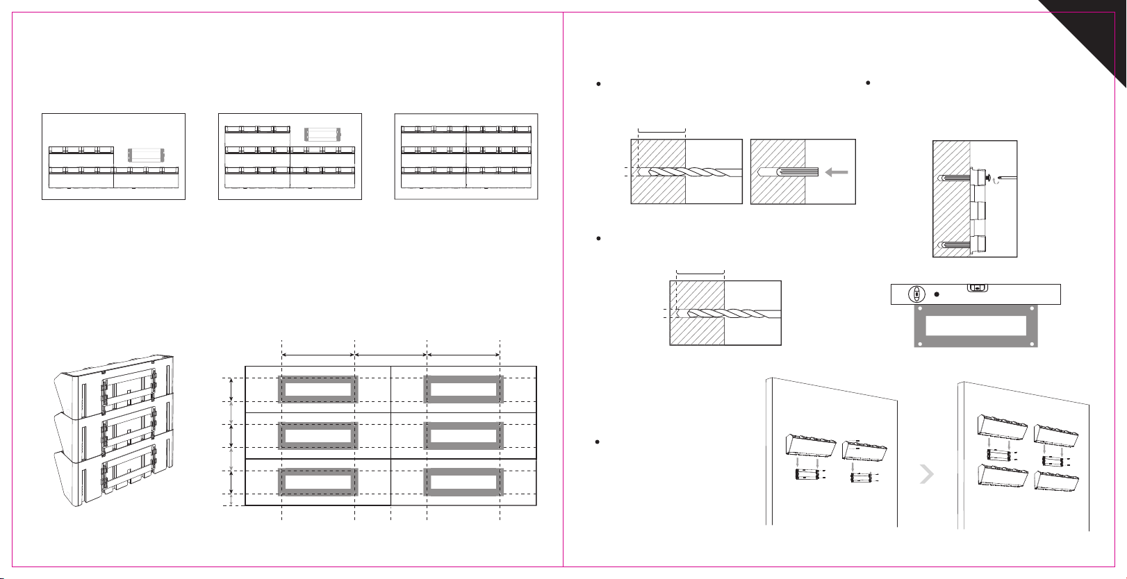
Označte na zeď první truhlík se 4 pozicemi otvorů
(281 mm x 90 mm od sebe). Poté označte stejné
pozice otvorů 91 mm nad spodní truhlík.
Viz obrázek 7
Začněte s instalací držáků na nejnižší úrovni. Ujistěte
se, že je dostatek místa pro nasazení truhlíku.
Postupujte s instalací dle nákresu:
90 mm
91 mm
90 mm
91 mm
90 mm
47.5 mm
281 mm
144. 5 mm
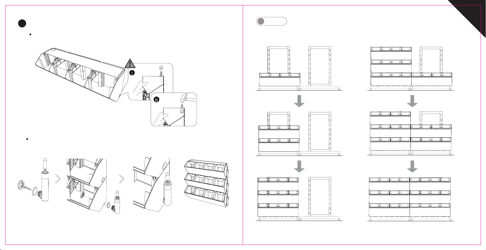
Svislá montáž dvou a více truhlíků
Montáž držáků truhlíků
1. truhlík
2. truhlík
3. truhlík
Obr. 7
Montáž více truhlíků
Pořadí instalace, jak je znázorněno níže:
nebo
Zeď
A
Zeď
A
Stojan
B
1
Postup vertikální montáže:
1. truhlík 1. truhlík 1. truhlík
2. truhlík 2. truhlík
3. truhlík
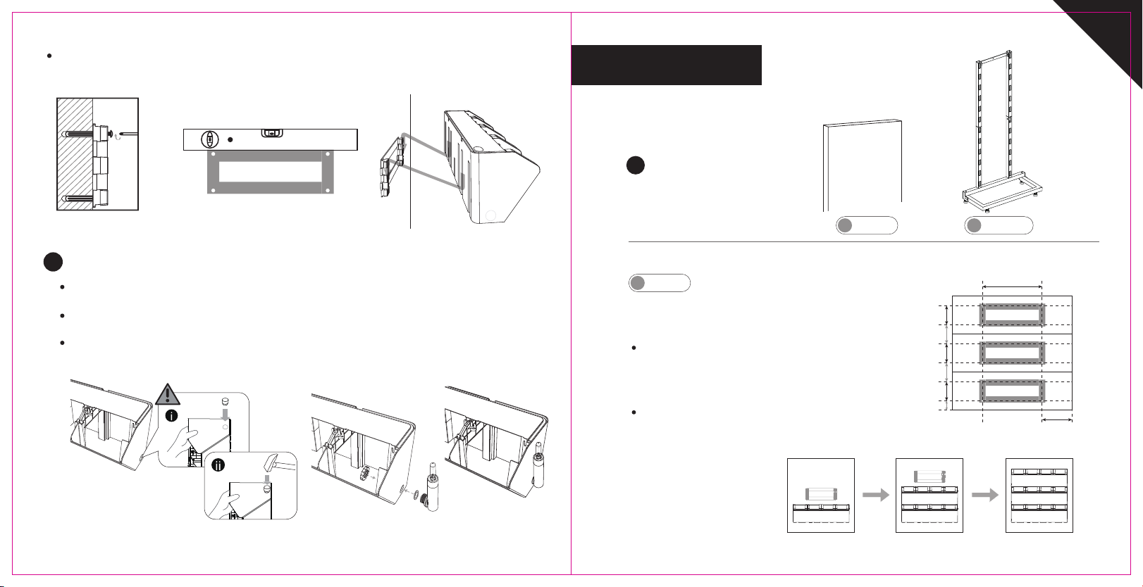
Umístěte děrovač do štěrbiny.
Při úderu kladívkem děrovač
nepřidržujte, předejdete možnému
poranění.
05
Instalace ukazatele hladiny vody
2
Obr. 6
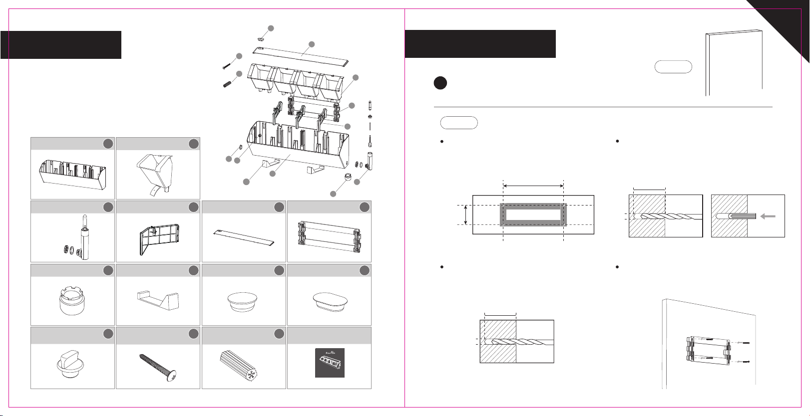
Pro instalaci ukazatele hladiny vody je nutné odstranit pomocí děrovače zátku otvoru pro ukazatel na boku truhlíku.
Ukazatel hladiny vody je takto možné instalovat na levou nebo pravou stranu truhlíku. Obrázek 6.
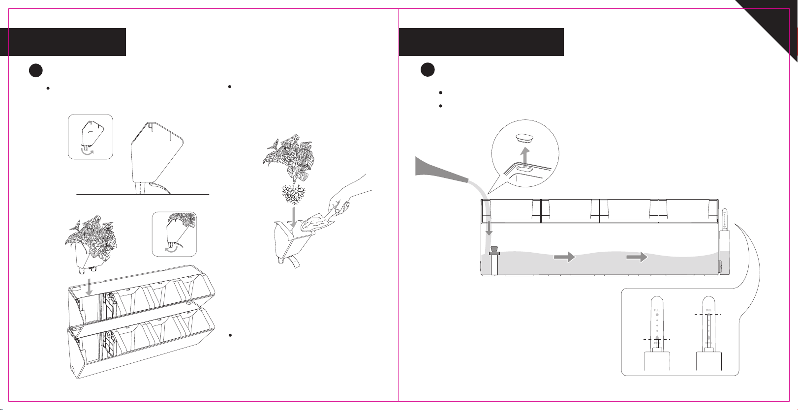
Vložte indikátor hladiny vody z vnějšku truhlíku, ujistěte se, že je těsnící kroužek na vnější straně,
zajistěte plastovou matici zevnitř. Obrázek 6.1.
Pokud potřebujete ukazatel hladiny vody demontovat, je nutné poté otvor utěsnit boční zátkou,
která je součástí balení.
Obr. 6.1
Než dotáhnete všechny šrouby zkontrolujte polohu držáků vodováhou. Vodorovná poloha je důležitá pro správnou
funkci zavlažovacího systému. Viz obrázky 5 a 5.1.
Nasaďte těleso květníku na vrchní hák držáku. Viz obrázek 5.2
Obr. 5 Obr. 5.1
Obr. 5.2
(není součástí)