476321 • MBD-10, Rev. 5, October 2022 Copyright 2022 © Greenheck Fan Corporation4
As a result of our commitment to continuous improvement, Greenheck reserves the right to change specifications
without notice.
Product warranties can be found online at Greenheck.com, either on the specific product page or in the
literature section of the website at Greenheck.com/Resources/Library/Literature.
®
Phone:
715.359.6171
•
Fax:
715.355.2399
•
Parts
:
800.355.5354
•
E-mail:
[email protected] •
W
ebsite:
www
.greenheck.com
Our Commitment
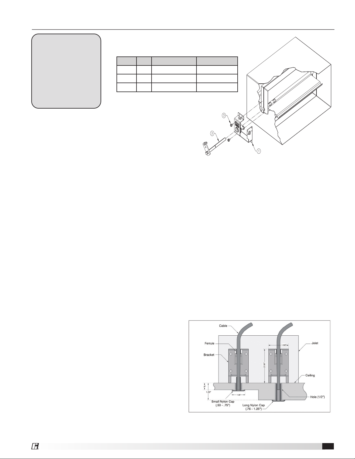
Item Qty Description Part Number
1 1 Cable Operator 1036540
2 1 Axle pin 1036728
3 2 Tek screw 415555
Tools Required:
Hammer
5⁄16 in. driver
Electric drill
9⁄16 in. drill bit
1⁄4in. bit driver
1⁄8in. hex key
5⁄64 in. hex key
Installation Instructions For Cable Operator with Square Wall/Ceiling Plate
1. Install the damper in the duct. Place fasteners so that they do not interfere with operation of the blades. The end
of the blade that has the lances will accept the cable operator drive pin. Place that side of the damper on the side
of the duct where the cable operator is to be located.
2. Cut a hole through the duct over the lanced blade axle bearing. The hole should be large enough for the axle pin
to slide through (approximately 9⁄16 in. diameter).
3. Set damper blade to full open. Slide the axle pin through the cable operator. Orientate lever on axle pin to 45
degrees, as shown. Insert the pin into the damper blade lances.
4. Pound the axle pin into the damper blade until the cable operator is firmly secured between the duct and the lever
on the axle pin.
5. Orientate cable operator such that it is running parallel to the duct. Install (2) Tek screws through screw holes in
the cable operator, through ductwork, and into damper frame as shown.
6. Insert the end of the cable into the coupling on the cable operator. Tighten the set screw.
7. Use 1⁄4in bit driver to rotate cable until set screws on cable operator gear are orientated such that they drive
perpendicular into adjacent faces of the square axle pin. Tighten set screws.
8. Run the cable to termination point and secure the cable at 3 foot intervals and every change in direction. Cables
should be taut or nearly taut with a 4 in. minimum turn radius. For cable runs longer than 20 feet, use of conduit is
recommended on straight run sections.
9. Fasten ceiling/wall plate to framing at the termination point, aligning
the depth so that the box is properly aligned with the finished surface.
(Illustration B)
10. For ceiling mount applications, use a 1⁄4in. bit driver to balance your
damper.
11. For wall mount applications, move guide and bushing to top knockout.
Pull the cable out towards you to allow driver access, then balance
damper. Push the cable back in place once balancing is complete.
12. Install cover plate. Illustration B