Velleman WB043 User manual
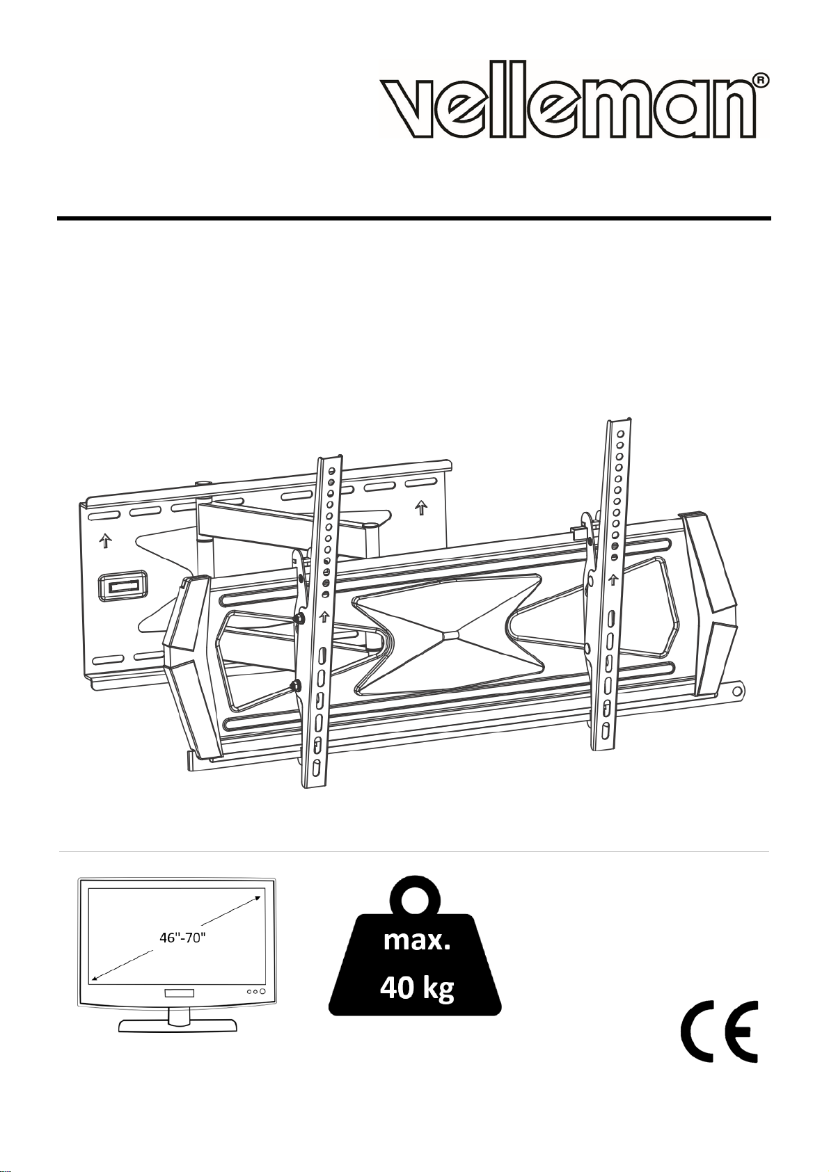
WB043
EN USER MANUAL ES MANUAL DEL USUARIO
NL HANDLEIDING DE BEDIENUNGSANLEITUNG
FR MODE D'EMPLOI PT MANUAL DO UTILIZADOR
VESA 300 x 300 | 400 x 200
400 x 400 | 600 x 400

WB043
V. 01 – 10/04/2017 2 ©Velleman nv
@@@
EN Component Checklist ES Lista de componentes
NL Overzicht onderdelen DE Stückliste
FR Liste de composants PT Lista de componentes
WB043
V. 01 – 10/04/2017 3 ©Velleman nv
EN Package M ES Embalaje M
NL Verpakking M DE M-Packung
FR Emballage M PT Embalagem M
EN Mounting hardware (not incl.) ES Material de montaje (no incl.)
NL Montagemateriaal (niet meegelev.) DE Befestigungsmaterial (nicht mitgelieferd)
FR Matériel de montage (non inclus) PT Acessórios de montagem (não incl.)

WB043
V. 01 – 10/04/2017 4 ©Velleman nv
EN Install decorative covers ES Instalar las cubiertas decorativas
NL De sierplaten bevestigen DE Die dekorativen Platten installieren
FR Fixer les plaques décoratives PT Instalar as capas decorativas
EN Wood stud wall mounting ES Montaje en una pared de madera
NL Montage aan een houten wand DE Montage an einer Holzwand
FR Montage sur une paroi en bois PT Montagem em viga de madeira
WB043
V. 01 – 10/04/2017 5 ©Velleman nv
WB043
V. 01 – 10/04/2017 6 ©Velleman nv
EN Solid brick and concrete mounting ES Montaje en un techo de ladrillos u hormigón
NL Montage op baksteen en beton DE Montage an einer Beton- oder Steindecke
FR Montage sur briques ou béton PT Montagem em tijolo ou bloco de cimento
WB043
V. 01 – 10/04/2017 7 ©Velleman nv
EN Installing adapter brackets ES Instalar los soportes adaptador
NL De bevestigingsadapter monteren DE Die Adapterhalter installieren
FR Fixer les supports d’adaptateur PT Instalar suportes do adaptador
WB043
V. 01 – 10/04/2017 8 ©Velleman nv
EN For flat back screens ES Para pantallas con la parte trasera plana
NL Voor schermen met vlakke achterkant DE Für Bildschirme mit einer flachen Rückseite
FR Pour écrans à dos plat PT Para ecrãs com a parte traseira plana
EN For Recessed Back Screen or to Access A/V
Inputs ES Para pantallas con otro tipo de parte trasera o para
pantallas con las entradas A/V en la parte trasera
NL Voor schermen met een achterkant met
uitsparing of voor toegang tot A/V-
ingangen
DE Für Bildschirme mit einer gesenkten Rückseite oder
mit A/V-Eingängen auf der Rückseite
FR Pour écrans avec rainure au dos ou pour
accéder aux entrées A/V PT Para ecrãs com uma reentrância na parte traseira
ou para aceder a entradas A/V

WB043
V. 01 – 10/04/2017 9 ©Velleman nv
EN Hanging the TV onto the wall plate ES Fijar la pantalla a la placa de pared
NL De tv aan de muurbeugel bevestigen DE Den Fernseher an der Wandhalterung befestigen
FR Fixer le téléviseur au support mural PT Pendurar a TV na parte instalada na parede

WB043
V. 01 – 10/04/2017 10 ©Velleman nv
EN Installing the antiskid blocks ES Instalar los bloques antideslizantes
NL De antislipblokjes plaatsen DE Die Antirutschblöcke installieren
FR Installer les blocs antidérapants PT Instalação dos bloqueadores anti-deslizamento
WB043
V. 01 – 10/04/2017 11 ©Velleman nv
EN Inserting the safety bar ES Instalar la barra de seguridad
NL De veiligheidsstang plaatsen DE Befestigen Sie die Sicherheitsstange
FR Insérez la barre de sécurité PT Colocar a barra de segurança
WB043
V. 01 – 10/04/2017 12 ©Velleman nv
EN Adjustment ES Ajustar el ángulo de inclinación
NL Instelling DE Den Neigungswinkel einstellen
FR Réglage PT Ajuste

WB043
V. 01 – 10/04/2017 13 ©Velleman nv
USER MANUAL
1. Safety Instructions
Do not begin the installation until you have read and understood the instructions and warnings contained in
this installation sheet.
If you have any questions regarding any of the instructions or warnings, please contact your local
distributor.
This mounting bracket was designed to be installed and utilized only as specified in this manual.
Improper installation of this product may cause damage or serious injury.
This product should only be installed by someone of good mechanical ability, with basic building
experiences and fully understanding of this manual.
Make sure that the supporting surface will safely support the combined load of the equipment and all
attached hardware and components.
Always use an assistant or mechanical lifting equipment to safely lift and position equipment.
Tighten screws firmly, but do not overtighten.
Overtightening can damage the items, greatly reducing their holding power.
This product is intended for indoor use only.
Using this product outdoors could lead to product failure and personal injury.
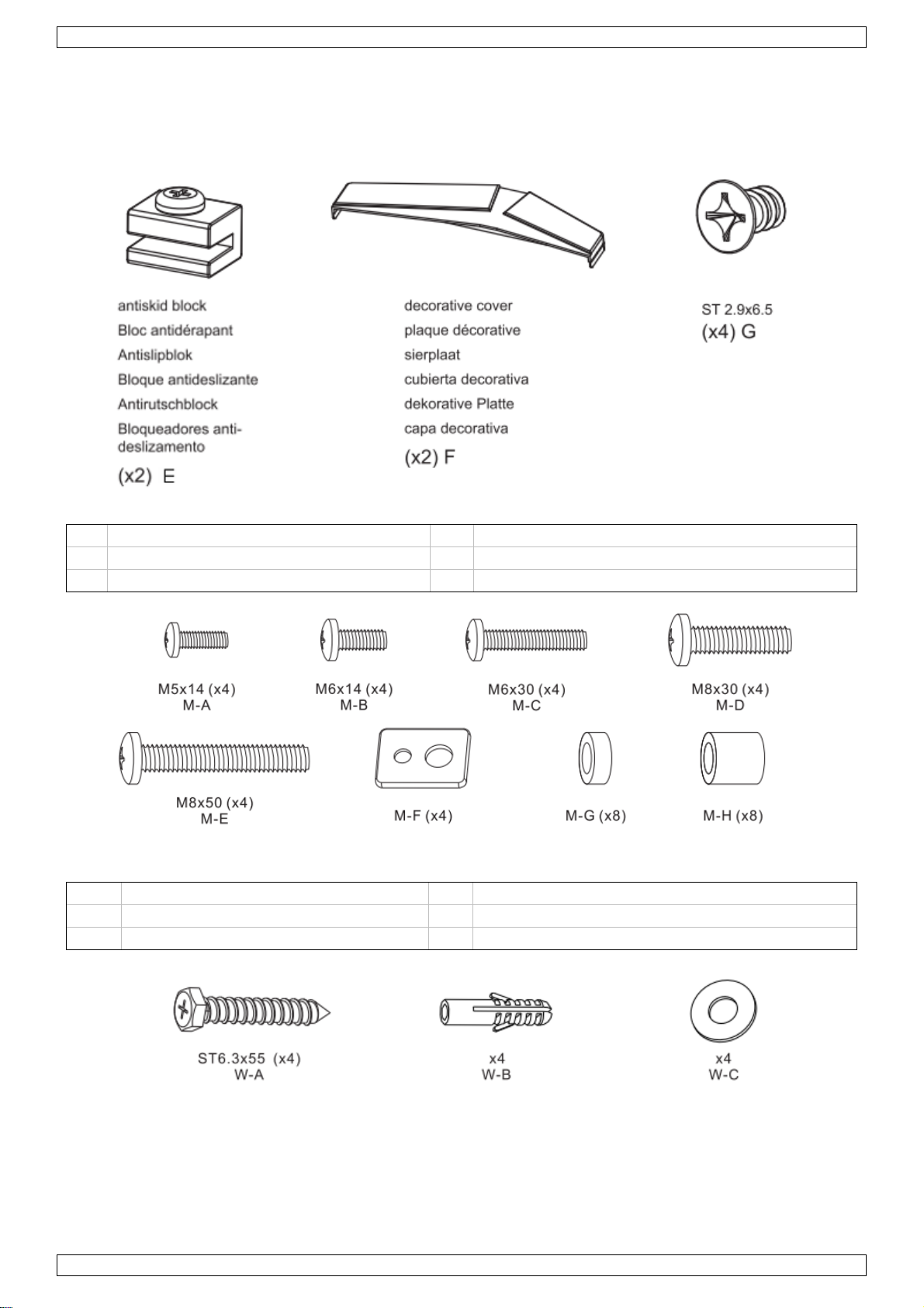
2. Component Checklist - Important
See images on page 2.
Ensure that you have received all parts according to the component checklist prior to installing. If any parts
are missing or faulty, contact your local distributor for a replacement.
Mounting hardware not included.
3. Mounting
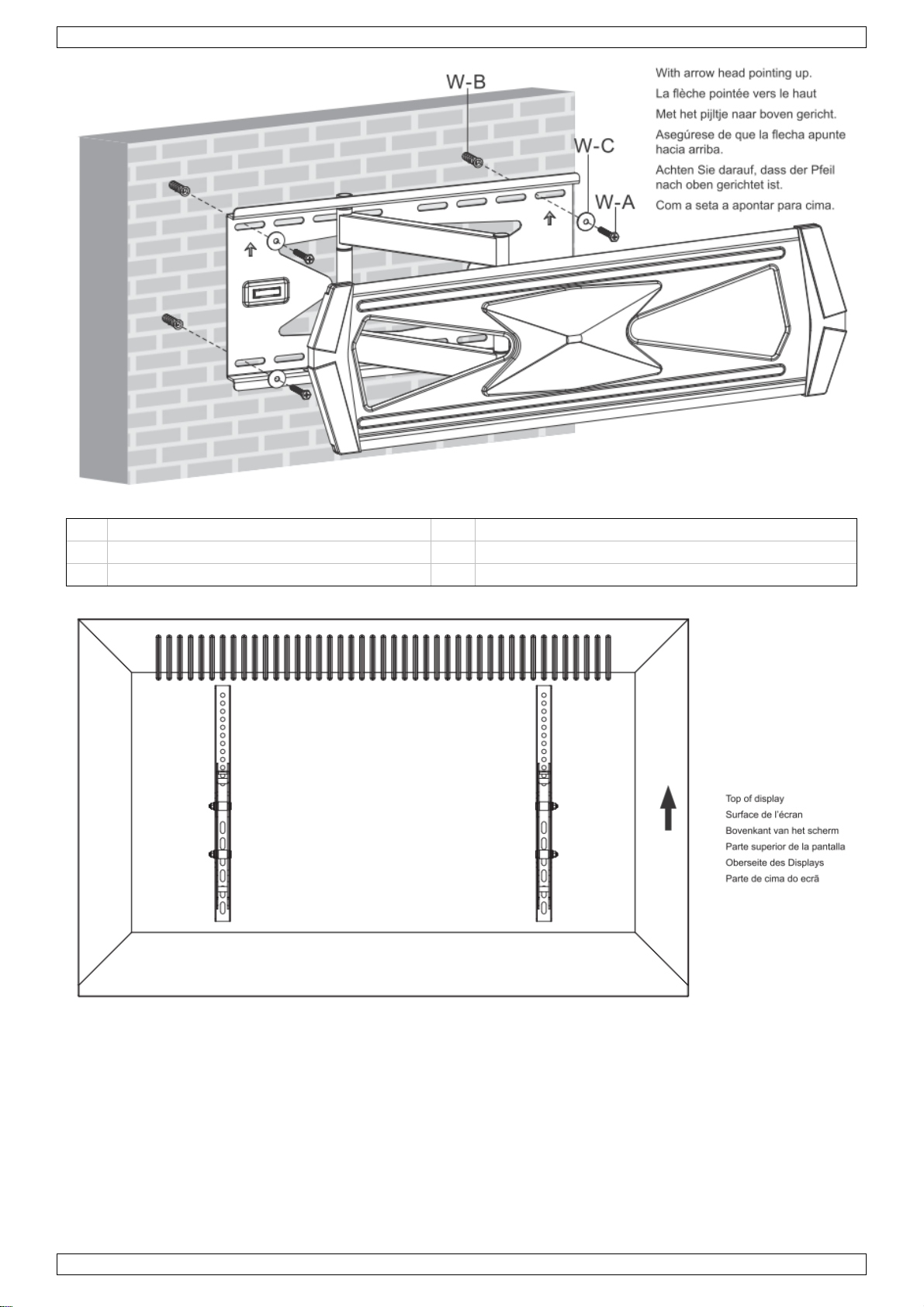
3.1 Install decorative covers
See images on page 2.
Attach decorative covers to wall plate using screws, with the gap of the decorative cover downward.
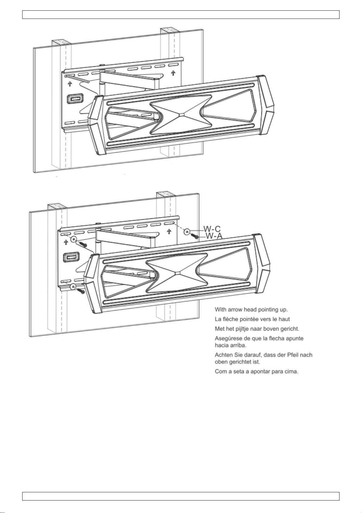
3.2 Wood stud wall mounting
See images on page 2.
Mark the exact location of the mounting holes.
Drill pilot holes.
Screw the wall mount onto the wall.
Warnings
Make sure that the mounting screws are anchored in the centre of the studs.
The use of a stud finder is highly recommended.
Installers are responsible for providing hardware for other types of mounting situations.
The installer must verify that the supporting surface will safely support the combined load of the equipment
and all attached hardware and components.
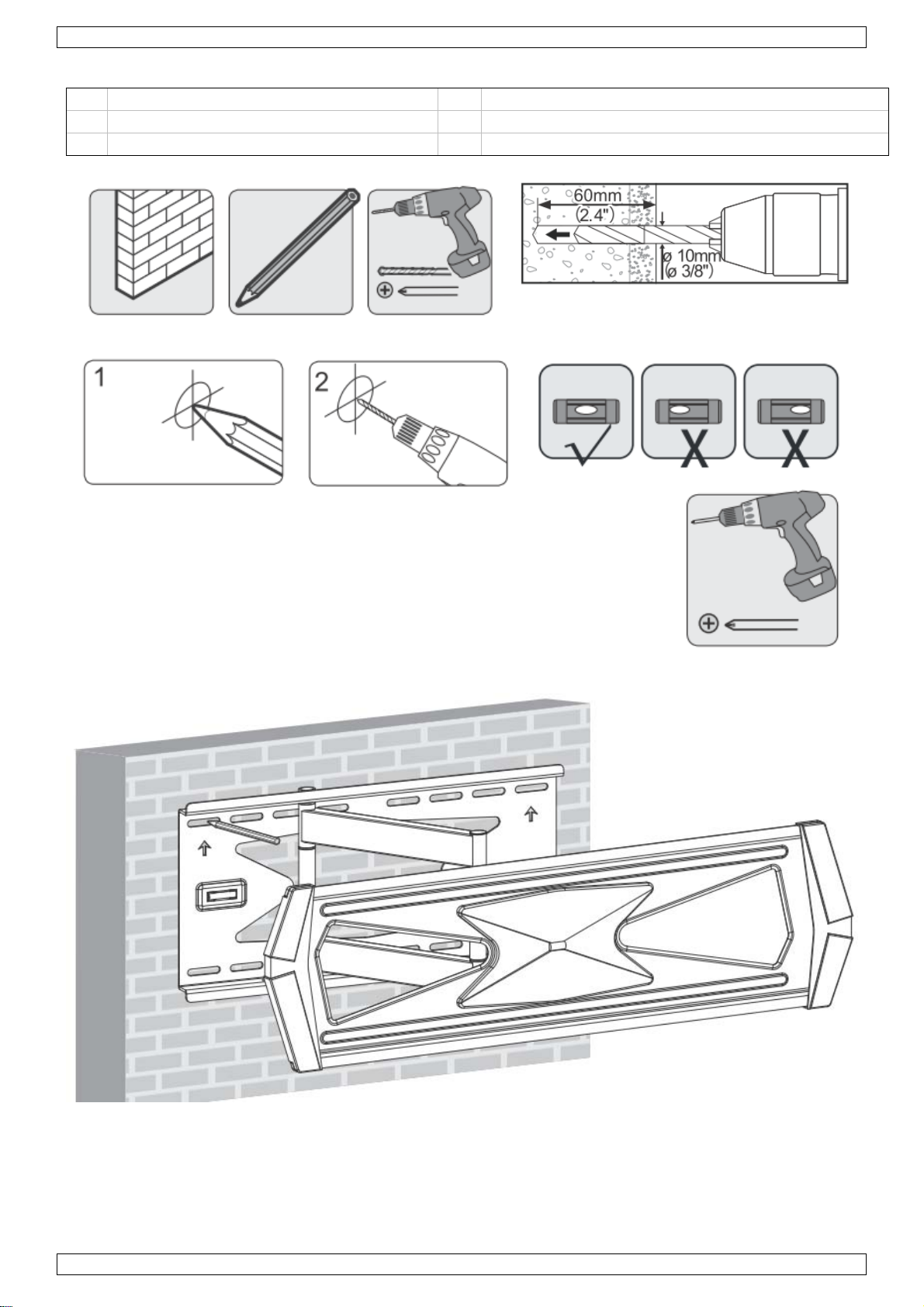
3.3 Solid brick and concrete mounting
See images on page 2.
Mark the exact location of the mounting holes.
Drill pilot holes.
Screw the wall mount onto the wall.
Warnings
When installing wall mounts on cinder blocks, verify that the actual concrete thickness is at least 1-3/8"
(35 mm) for using the concrete anchors.
Do not drill into mortar joints! Be sure to mount in a solid part of the block, generally 1" (25 mm) minimum
from the side of the block.
WB043
V. 01 – 10/04/2017 14 ©Velleman nv
We suggest to use an electric drill on slow setting to drill the hole instead of a hammer drill to avoid
breaking out the back of the hole when entering a void or cavity.
The installer must verify that the supporting surface will safely support the combined load of the equipment
and all attached hardware and components.
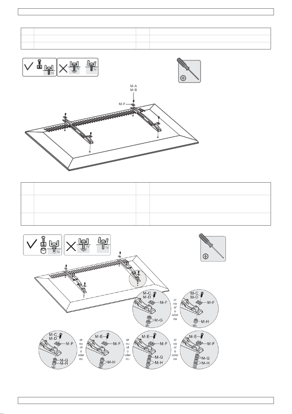
3.4 Installing Adapter Brackets
For flat back screens: See images on page 2
For recessed back screen or to access A/V inputs: See images on page 2
Notes
Choose appropriate screws, washers and spacers (if necessary) according to the type of screen.
Position the adapter brackets as close as possible to the centre of the display.
Screw the adapter brackets onto the display.
Tighten all screws but do not over tighten.
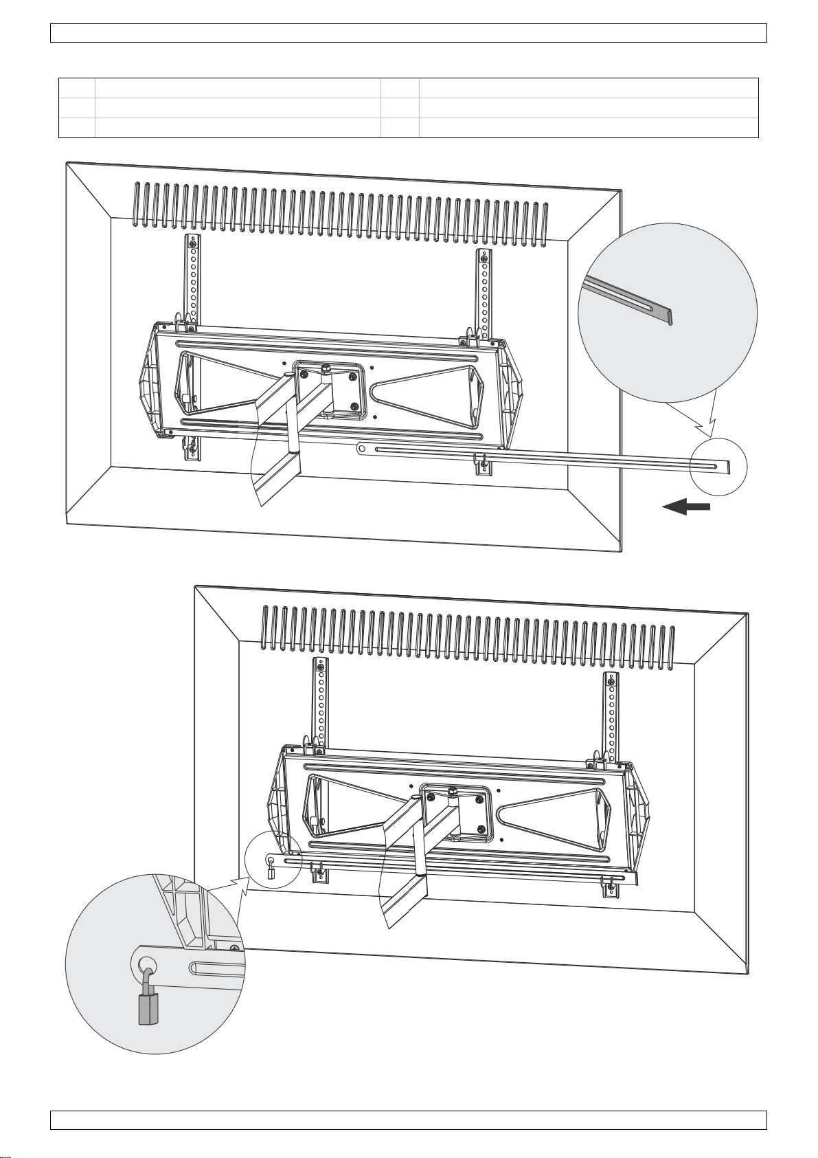
3.5 Hanging the TV onto the wall plate
See images on page 2.
Two qualified persons are required.
3.6 Installing the antiskid blocks
See images on page 2.
Install both antiskid blocks as close to the adapter brackets as possible.
Tighten screws on the antiskid blocks using a proper screwdriver to prevent display from moving.
3.7 Inserting the safety bar
See images on page 2.
Insert the safety bar to secure the rails.
Use a padlock to prevent TV from being stolen (padlock not included).
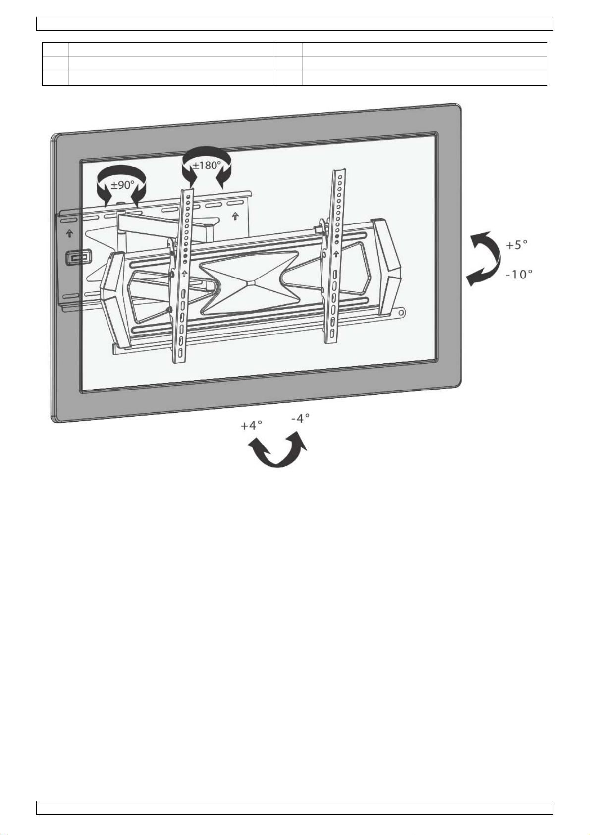
4. Adjustment
See images on page 2
Adjust to the desired location or tilt.
5. Maintenance
Check that the bracket is secure and safe to use at regular intervals (at least every three months).
Please contact your dealer if you have any questions.
6. Technical Specifications
TV size 46" - 70" (117-178 cm)
max. load 40 kg / 88 lb
TV to wall distance 77 - 548 mm
tilt -10° to +5°
swivel 180°
level adjustment -4° to +4°
VESA mount 300 x 300 - 400 x 200 - 400 x 400 - 600 x 400
Use this device with original accessories only. Velleman nv cannot be held responsible in the event
of damage or injury resulting from (incorrect) use of this device.
For more info concerning this product and the latest version of this manual, please visit our website
www.velleman.eu.
The information in this manual is subject to change without prior notice.
© COPYRIGHT NOTICE
The copyright to this manual is owned by Velleman nv. All worldwide rights reserved. No part of this
manual may be copied, reproduced, translated or reduced to any electronic medium or otherwise without the
prior written consent of the copyright holder.

WB043
V. 01 – 10/04/2017 15 ©Velleman nv
HANDLEIDING
1. Veiligheidsinstructies
Voor u aan de installatie begint, zorg ervoor dat u de instructies en waarschuwingen beschreven in deze
handleiding hebt gelezen en begrepen.
Indien u vragen hebt met betrekking tot een van de instructies of waarschuwingen, neem dan contact op
met uw plaatselijke verdeler.
Deze montagebeugel is enkel geschikt voor montage en gebruik zoals beschreven in deze handleiding.
Een onjuiste montage kan schade aan het product of ernstige letsels veroorzaken.
Dit product mag alleen worden geïnstalleerd door iemand met een degelijke mechanische kennis, die
ervaring heeft met algemene huizenbouw en die deze instructies volledig begrijpt.
Controleer of het oppervlak waaraan de houder bevestigd is, het gewicht van de beugel en het toestel veilig
kan dragen.
Maak altijd gebruik van een assistent of een mechanisch liftapparaat om de apparatuur op een veilige
manier op te tillen en te positioneren.
Draai de schroeven stevig vast, maar niet te strak.
Het te strak vastdraaien van de schroeven kan ervoor zorgen dat ze beschadigd raken, waardoor hun
draagkracht enorm kan worden gereduceerd.
Dit product is alleen bedoeld voor gebruik binnenshuis.
Gebruik van dit product buitenshuis zou kunnen leiden tot falen van het product en persoonlijke
verwondingen.
2. Overzicht onderdelen - Belangrijk
Zie afb. op pagina 2.
Controleer voor de montage of u alle onderdelen hebt ontvangen. Indien er een tekort of gebrek wordt
vastgesteld, contacteer uw lokale dealer voor een reserveonderdeel.
Montagemateriaal niet meegeleverd.
3. Montage
3.1 De sierplaten bevestigen
Zie afb. op pagina 2.
Bevestig de sierplaten (met opening naar beneden gericht) aan de muurplaat met de schroeven.
3.2 Montage aan een houten wand
Zie afb. op pagina 2.
Bepaal en markeer de exacte plaats van de montagegaten.
Boor gaten voor.
Schroef de muurplaat tegen de muur.
Waarschuwingen
Zorg ervoor dat de montageschroeven in het midden van de planken bevestigd zijn.
Het gebruik van een balkzoeker is sterk aanbevolen.
De installateurs zijn verantwoordelijk voor de hardware voor andere montagetypes.
De installateur moet controleren dat het dragend oppervlak de gecombineerde belasting van de apparatuur
en alle eraan bevestigde hardware en componenten veilig zal ondersteunen.
3.3 Montage op baksteen en beton
Zie afb. op pagina 2.
Bepaal en markeer de exacte plaats van de montagegaten.
Boor gaten voor.
Schroef de muurplaat tegen de muur.
Waarschuwingen
Bij montage op sintelblokken, verifieer of het beton minstens een dikte heeft van 1-3/8" (35 mm) voor het
gebruik van betonpluggen.

WB043
V. 01 – 10/04/2017 16 ©Velleman nv
Boor niet in metselvoegen! Zorg ervoor dat de montage gebeurt op een massief deel van het blok, minstens
1" (25 mm) van de rand van het blok.
Wij raden u aan om een elektrische boormachine te gebruiken met trage snelheid i.p.v. een
klopboormachine om te vermijden dat het geboorde gat groter wordt bij het stuiten op een leegte of holte.
De installateur moet controleren dat het dragend oppervlak de gecombineerde belasting van de apparatuur
en alle eraan bevestigde hardware en componenten veilig zal ondersteunen.
3.4 De bevestigingsadapters monteren
Voor schermen met een vlakke achterkant: Zie afb. op pagina 2
Voor schermen met een achterkant met uitsparing of met A/F- ingangen aan de achterkant: Zie afb. op
pagina 2
Opmerkingen
Kies de geschikte schroeven, dichtingsringen, en afstandsbussen (indien nodig) afhankelijk van het type
scherm.
Leg de bevestigingsadapters zo precies mogelijk in het midden van de scherm.
Schroef de bevestigingsadapters aan het scherm.
Draai de schroeven stevig vast, maar niet te strak.
3.5 De tv aan de muurplaat bevestigen
Zie afb. op pagina 2.
De montage vereist twee bekwame volwassenen.
3.6 De antislipblokjes plaatsen
Zie afb. op pagina 2.
Plaats beide antislipblokjes zo dicht mogelijk tegen de bevestigingsadapters.
Draai de schroeven stevig vast op de antislipblokjes met een geschikte schroevendraaier zodat het
televisiescherm niet meer kan bewegen.
3.7 De veiligheidsstang plaatsen
Zie afb. op pagina 2.
Schuif de veiligheidsstang om de rails te vast te zetten.
Gebruik een hangslot om te voorkomen dat het televisiescherm wordt gestolen (hangslot niet
meegeleverd).
4. Instelling
Zie afb. op pagina 2
Stel de gewenste draai- en zwenkhoek in.
5. Onderhoud
Controleer regelmatig of de beugel stevig vastzit en veilig is in gebruik (minstens om de 3 maanden).
Mocht u nog vragen hebben, gelieve uw dealer te contacteren.
6. Technische specificaties
afmetingen TV 46" - 70" (117-178 cm)
max. last 40 kg / 88 lb
afstand TV tot muur 77 - 548 mm
kanteling -10° tot +5°
zwenkbaar 180°
niveauregeling -4° tot +4°
VESA 300 x 300 - 400 x 200 - 400 x 400 - 600 x 400
Gebruik dit toestel enkel met originele accessoires. Velleman nv is niet aansprakelijk voor schade of
kwetsuren bij (verkeerd) gebruik van dit toestel.
Voor meer informatie over dit product en de laatste versie van deze handleiding, zie
www.velleman.eu.

WB043
V. 01 – 10/04/2017 17 ©Velleman nv
De informatie in deze handleiding kan te allen tijde worden gewijzigd zonder voorafgaande
kennisgeving.
© AUTEURSRECHT
Velleman nv heeft het auteursrecht voor deze handleiding. Alle wereldwijde rechten voorbehouden.
Het is niet toegestaan om deze handleiding of gedeelten ervan over te nemen, te kopiëren, te vertalen, te
bewerken en op te slaan op een elektronisch medium zonder voorafgaande schriftelijke toestemming van de
rechthebbende.

WB043
V. 01 – 10/04/2017 18 ©Velleman nv
MODE D'EMPLOI
1. Consignes de sécurité
Ne commencez pas à installer avant d’avoir lu et compris les instructions et avertissements du présent
manuel d’installation.
Si vous avez une question quelconque concernant une instruction ou avertissement, veuillez contacter votre
distributeur local.
Le support de montage a été conçu pour être installé et utilisé uniquement comme indiqué dans ce manuel.
Une installation incorrecte pourrait entraîner une défaillance du produit ou des blessures graves.
Ce produit doit être installé uniquement par une personne possédant de bonnes connaissances en
mécanique, des notions de base en construction d’immeubles, et qui comprend parfaitement les présentes
instructions.
Assurez-vous que la surface d’appui est en bon état et qu’elle supportera correctement la charge cumulée
de l’équipement et de l’ensemble du matériel et des pièces de fixation.
Faîtes-vous toujours aider ou utilisez un équipement de levage mécanique pour soulever et positionner
l’équipement correctement.
Serrez les vis correctement, mais pas à l’excès.
Un serrage excessif peut endommager les vis, réduisant fortement leur résistance. Un serrage excessif
pourrait endommager les vis, réduisant fortement leur résistance.
Ce produit est destiné uniquement à un usage intérieur.
L’utilisation de ce produit à l’extérieur pourrait entraîner une défaillance du produit et des blessures
physiques.
2. Liste de composants - Important
Voir illustrations en page 2.
Assurez-vous d'avoir reçu toutes les pièces affichées sur la liste de composants avant le montage. Si une
pièce apparaît comme manquante ou défectueuse, contactez votre distributeur local pour une pièce de
rechange.
Matériel de montage non inclus.
3. Montage
3.1 Fixer les plaques décoratives
Voir illustrations en page 2.
Attachez les plaques décoratives, avec l’ouverture de la plaque décorative orientée vers le bas, à la plaque
murale avec les vis.
3.2 Montage sur une paroi en bois
Voir illustrations en page 2.
Localisez et marquez l’emplacement exact des trous de montages.
Forez des avant-trous.
Vissez la plaque murale contre le mur.
Avertissements
Vérifiez que les vis de fixation sont ancrées au centre des poteaux.
L’utilisation d’un détecteur de montants est fortement recommandée.
Les installateurs sont responsables pour la procuration du hardware pour d'autres applications de montage.
L’installateur doit s’en assurer que la surface d’appui est en bon état et qu’elle supportera correctement la
charge cumulée de l’équipement et de l’ensemble du matériel et des pièces de fixation.
3.3 Montage sur du béton plein ou un bloc de parpaing
Voir illustrations en page 2.
Localisez et marquez l’emplacement exact des trous de montages.
Forez des avant-trous.
Vissez la plaque murale contre le mur.

WB043
V. 01 – 10/04/2017 19 ©Velleman nv
Avertissements
En cas de montage sur des blocs de cendre, vérifiez que l’épaisseur nominale du béton est d’au moins -3/8”
(35 mm) pour l’utilisation des chevilles nylon.
Ne percez pas dans les joints de mortier ! Vérifiez que les vis et les ancres sont fixées sur des zones solides
de la surface, généralement au moins 1” (25 mm) du côté du bloc.
Nous vous conseillons d’utiliser une perceuse électrique au lieu d’un marteau-piqueur pour éviter que le
trou percé s’agrandi en cas d’un trou ou cavité.
L’installateur doit s’en assurer que la surface d’appui est en bon état et qu’elle supportera correctement la
charge cumulée de l’équipement et de l’ensemble du matériel et des pièces de fixation.
3.4 Fixer les supports d'adaptateur
Pour écrans à dos plat : Voir illustrations en page 2
Pour écrans avec rainure au dos ou pour accéder aux entrées A/V : Voir illustrations en page 2
Notes
Utilisez les vis, rondelles, et entretoises (si nécessaire) appropriées selon le type d'écran.
Positionnez les supports d'adaptateur aussi proche que possible vers le centre de l'écran.
Vissez les supports d'adaptateur à l'écran.
Serrez fermement les vis, mais pas à l’excès.
3.5 Accrocher l'écran à la plaque mural
Voir illustrations en page 2.
Le montage doit être effectué par deux personnes qualifiées.
3.6 Installer les blocs antidérapants
Voir illustrations en page 2.
Installez les 2 blocs antidérapants aussi proches que possible contre les supports d’adaptateur.
Serrez les vis sur les blocs antidérapants avec un tournevis approprié pour éviter que l’écran ne puisse plus
bouger.
3.7 Insérer la barre de sécurité
Voir illustrations en page 2.
Faîtes glisser la barre de sécurité pour sécuriser les rails.
Utilisez un cadenas pour éviter que l’écran ne soit volé (cadenas non incl.).
4. Réglage
Voir illustrations en page 2
Réglez l’angle de rotation et d’inclinaison.
5. Entretien
Vérifiez régulièrement à ce que le support soit bien sécurisé et sûr à l'emploi (au moins tous les 3 mois).
Pour toute question, veuillez contacter votre distributeur.
6. Spécifications techniques
dimensions TV 46" - 70" (117-178 cm)
charge max. 40 kg / 88 lb
distance TV-mur 77 - 548 mm
inclinaison de -10° à +5°
pivotant 180°
ajustement de niveau de -4° à +4°
VESA 300 x 300 - 400 x 200 - 400 x 400 - 600 x 400
N'employer cet appareil qu’avec des accessoires d’origine. La SA Velleman ne peut, dans la mesure
conforme au droit applicable être tenue responsable des dommages ou lésions (directs ou indirects)
pouvant résulter de l’utilisation de cet appareil.

WB043
V. 01 – 10/04/2017 20 ©Velleman nv
Pour plus d'informations concernant cet article et la dernière version de ce mode d'emploi,
consulter notre site www.velleman.eu.
Les spécifications et le continu de ce mode d'emploi peuvent être modifiés sans notification
préalable.
© DROITS D’AUTEUR
Velleman SA est l’ayant droit des droits d’auteur de ce mode d'emploi. Tous droits mondiaux
réservés. Toute reproduction, traduction, copie ou diffusion, intégrale ou partielle, du contenu de ce mode
d'emploi par quelque procédé ou sur tout support électronique que ce soit est interdite sans l’accord préalable
écrit de l’ayant droit.
Other manuals for WB043
1
Table of contents
Languages:
Other Velleman TV Mount manuals

Velleman
Velleman WB023 User manual

Velleman
Velleman WB046 User manual

Velleman
Velleman HQSB10001 User manual

Velleman
Velleman WB008 User manual

Velleman
Velleman WB032 User manual

Velleman
Velleman WB050 User manual

Velleman
Velleman WB051 User manual

Velleman
Velleman VDLLB6 User manual

Velleman
Velleman WB036 User manual


