4
Greenlee Fairmont Textron / Subsidiary of Textron Inc. 4455 Boeing Drive, Rockford, IL 61109 815/397-7070
Pistol Grip Chain Saw
GREENLEE
FAIRMONT
Safety Information
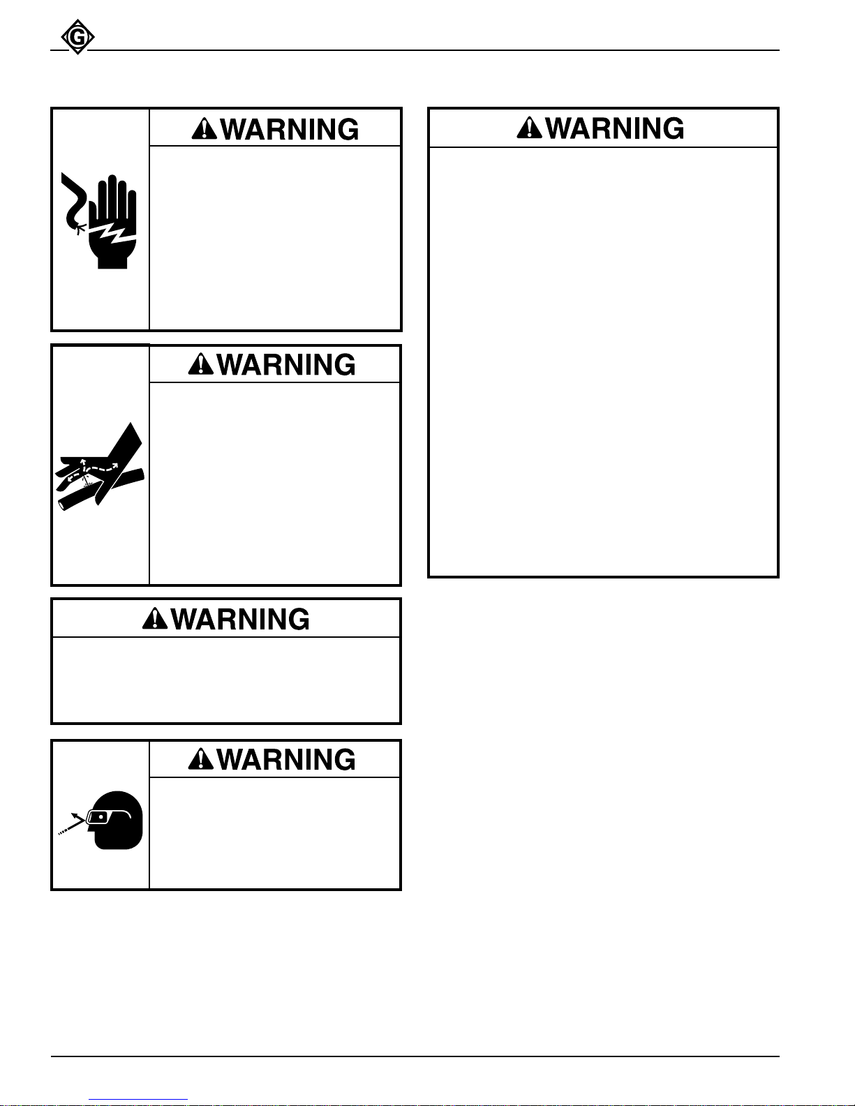
Electrical Shock Hazard:
This tool is not insulated. When
using this unit near energized
electrical lines, use only certified
non-conductive hoses and proper
personal protective equipment.
Failure to observe this warning
could result in severe injury or
death.
• Do not change accessories, inspect, adjust or
clean tool when it is connected to a power
source. Accidental start-up can result in
serious injury.
• Maintain a firm grip on tool, using both hands
at all times. Serious injury can result if an
operator does not control the tool.
• Do not lock trigger in the Power-ON position.
Operator cannot stop tool when trigger is
locked.
• Do not remove or modify tool’s two-step safety
trigger. Accidental start-up can result in serious
injury.
• Always disconnect tool from power source
before attempting to adjust or service the chain
saw. Accidental start-up can result in serious
injury.
• Always wear protective gloves when handling
or adjusting the saw chain. The saw chain can
cut even when stationary.
Failure to observe these warnings could result in
severe injury or death.
• Kickback hazard:
Kickback may occur when the moving saw chain
at the nose or tip of the guide bar touches an
object, or when the wood closes in and pinches
the saw chain in the cut. Tip contact in some
cases may cause a lightning-fast reverse
reaction, kicking the guide bar up and back
towards the operator.
• Pushback hazard:
Pinching the saw chain along the top of the
guide bar may push the guide bar rapidly back
towards the operator.
• Do not operate tool with a damaged or worn saw
chain. An improperly sharpened, dull, worn or
damaged saw chain increases the risk of
kickback and pushback.
Failure to observe these warnings could result in
severe injury or death.
Skin Injection Hazard:
High pressure oil easily punctures
skin causing serious injury,
gangrene or death. If injured seek
medical help immediately to remove
oil.
Do not use fingers or hands to
check for leaks.
Depressurize hydraulic system
before servicing.
Do not disconnect tool, hoses or fittings while the
power unit is running or if the hydraulic fluid is hot.
Exposure to hot hydraulic fluid can cause serious
burns.
Wear eye protection when using
this tool.
Failure to wear eye protection can
result in serious eye injury from
flying debris or hydraulic oil.


(36) parts catalog")