ICS 603GC User manual

© 2006 ICS, Blount Inc. P/N 518538 Jul 06
603GC
UTILITY GAS SAW
OPERATOR’S MANUAL


TITLE
603GC OPERATOR’S MANUAL
3
P/N 518538 Jul 06 © 2006 ICS, Blount Inc.
TABLE OF CONTENTS
SYMBOLS & LABELS 4
SAFETY 5
TECHNICAL SPECIFICATIONS 8
SET-UP 9
OPERATION 11
MAINTENANCE 16
TROUBLESHOOTING 23
REFERENCE 24

603GC OPERATOR’S MANUAL
4© 2006 ICS, Blount Inc. P/N 518538 Jul 06
SYMBOLS & LABELS
THE FOLLOWING SYMBOLS & DEFINITIONS ARE FOUND THROUGHOUT THIS MANUAL AND
ARE DESIGNED TO MAKE YOU AWARE OF POTENTIAL HAZARDS OR UNSAFE PRACTICES.
A potentially hazardous situation exists which, if not avoided,
could result in death or serious injury.
A potentially hazardous situation exists which, if not avoided,
may result in minor or moderate injury or property damage.
A potential situation exists which, if not avoided, may result in
product or property damage.
THE FOLLOWING SYMBOLS & LABELS MAY BE FOUND IN THIS MANUAL OR ON THE SAW
Read the operator’s manual carefully and understand the
contents before you use this equipment.
Always use:
• Protective helmet
• Ear protection
• Protective glasses or full face protection
Wear hand protection
IMPORTANT
WARNING
CAUTION

603GC OPERATOR’S MANUAL
5
P/N 518538 Jul 06 © 2006 ICS, Blount Inc.
SAFETY
WARNING
THE FOLLOWING SYMBOL APPLIES TO ALL THE ITEMS LISTED ON THIS PAGE
A potentially hazardous situation exists which, if not avoided,
could result in death or serious injury.
Diamond chain breakage can result in high-speed ejection of parts, which can result in death
or serious personal injury to operators or bystanders. The items listed below are critical to
minimizing the risk of diamond chain breakage and injury.
• DO NOT operate the saw with a damaged, modified, broken, or missing side cover,
bottom guard, or guard flap. The side cover, bottom guard, and guard flap provides
protection against contact with moving parts, ejected debris, broken diamond chain,
thrown water and concrete slurry.
• DO NOT insert the saw into a slot narrower than the diamond chain segments. Rapid
pushback might occur. Reference: Most diamond segments are .225 inches (5.72 mm)
wide.
• DO NOT use damaged, modified or improperly repaired diamond chain.
• DO NOT run the saw upside-down. Concrete debris can fly back into the operator’s face.
• DO NOT cut ductile iron pipe with the saw. Segment loss or diamond chain breakage may
occur.

603GC OPERATOR’S MANUAL
6© 2006 ICS, Blount Inc. P/N 518538 Jul 06
SAFETY
CAUTION
THE FOLLOWING SYMBOL APPLIES TO ALL ITEMS LISTED ON THIS PAGE
A potentially hazardous situation exists which, if not avoided,
may result in minor or moderate injury or property damage.
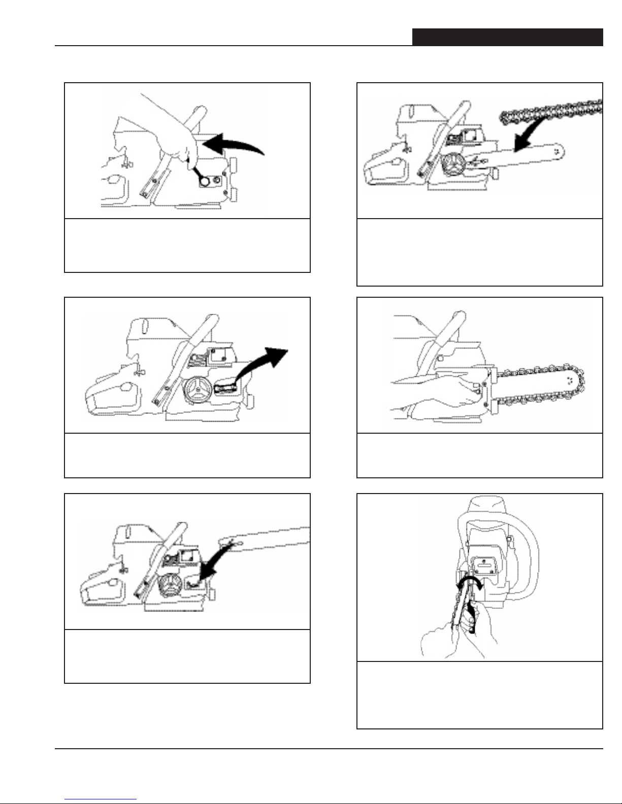
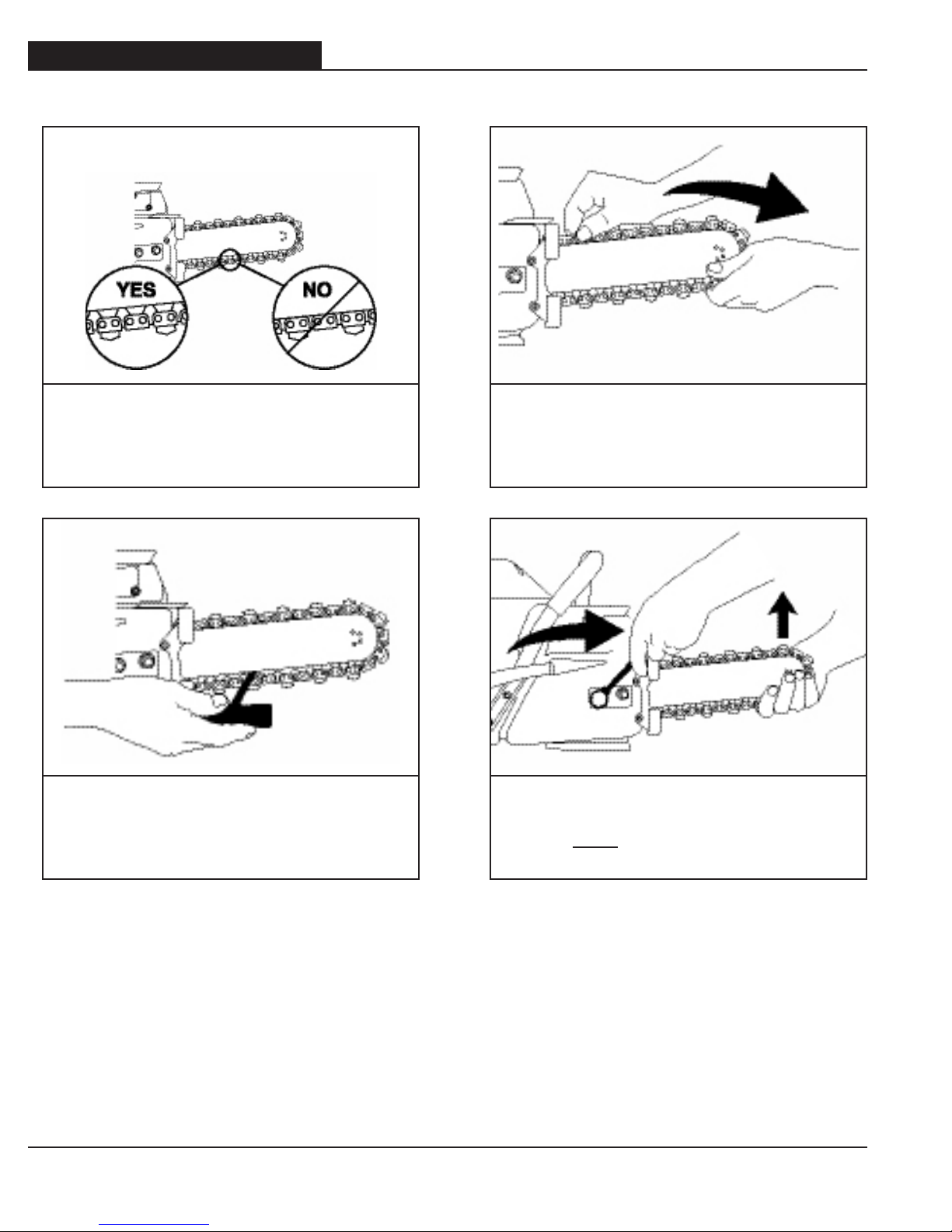
• Always turn the saw OFF when performing maintenance on the saw including diamond
chain tensioning.
• Never use equipment that is not functioning properly. Have the saw repaired by qualified
service personnel.
• Turn engine OFF before refueling. Keep away from open flame. Always provide adequate
ventilation when handling fuel. Move the saw at least 10 feet (3 m) away from refueling
area before starting.
• Diamond chains require a minimum water pressure of 20 psi (1.4 bar). Insufficient water
supply may result in excessive wear to the diamond chain, which can lead to loss of
strength and diamond chain breakage.
• Never start the saw unless the guide bar, diamond chain and side cover are properly
installed.
GENERAL SAFETY PRECAUTIONS
• Always wear protective clothing, including hard hat, eye protection, hearing protection, and
gloves.
• Avoid loose fitting clothing.
• Perform safety checks before starting each day.
• Always operate tool with solid footing and with both hands on cut-off saw.
• Remove or control slurry to prevent slippery conditions while cutting.
• Be sure there are no obstructions (plumbing, electrical conduit, air ducts) and no unnecessary
people present.
• Set up a well-marked safety zone with a roped boundary and clear signs.
• Provide adequate ventilation when working in an enclosed area. Breathing exhaust gases is
dangerous.
• To avoid electrocution, check for live electrical wiring near cutting area.

603GC OPERATOR’S MANUAL
7
P/N 518538 Jul 06 © 2006 ICS, Blount Inc.
SAFETY
IMPORTANT
THE FOLLOWING SYMBOL APPLIES TO ALL ITEMS LISTED ON THIS PAGE
A potential situation exists which, if not avoided, may result in
product or property damage.
Note: The saw is equipped with a two-stroke engine and must always be run using a mixture
of gasoline and ICS two-stroke engine oil (25:1). It’s important to accurately measure the
amount of oil to be mixed to ensure that correct mixture is obtained. When mixing small
amounts of fuel, even small inaccuracies can drastically affect the ratio of the mixture.
• Use high quality, unleaded gasoline with a minimum octane rating of 90. If lower octane
gasoline is used, engine temperature will increase which will result in a piston seizure.
• Fuel mixture: 25:1 gasoline/oil mixture. Incorrect fuel mixture will cause piston seizure.
• Use ICS®brand two-stroke engine oil, or other high quality 2-stroke oil that has been
formulated for air cooled power equipment.
• Never use two-stroke oil formulated for water-cooled two-cycle engines, such as
outboard motor oil.
• Never use motor oil intended for four-stroke engines.
ENGINE BREAK-IN
• It is very important to break-in a new engine to “seat” all moving parts, especially the
piston rings.
• To break-in the engine, run one full tank of 25:1 fuel at idle, cycling the throttle every
5 to 10 minutes to prevent loading.
• Failure to break-in an engine may result in piston seizure.

603GC OPERATOR’S MANUAL
8© 2006 ICS, Blount Inc. P/N 518538 Jul 06
TECHNICAL SPECIFICATIONS
Engine Type 2-stroke Single Cylinder Air Cooled
Displacement 3.9 cu-in (64cc)
Horsepower 4.2 HP (3.1 kw) @ 9,500 RPM
Torque 32 in-lbs (3.6 Nm)
Engine Speed 8,700 +/- 500 rpm
2,800-3,200 rpm idle
Diamond Chain Speed In cut = 4,000 sfm
No load = 5,100 sfm
Weight 16.6 lbs (9.1 kg) with guide bar and
diamond chain
Cut Depth Up to 9 inches (22.9cm)
Dimensions
17 inches (44cm) length
10 inches (25.5cm) height
11.6 inches (29.5cm) width
Air Filter Dry nylon
Carburetor Walbro HAD146, throttle shaft sealed,
pressure compensating
Starter Standard Recoil
Ignition Special water resistant electronic
ignition
Clutch Three-weight, single spring
Fuel ratio 25:1 gasoline-to-oil
Fuel Capacity 34 oz (1 Liter)
15-18 minutes run time per tank
Water Supply Minimum 20psi (1.5 bar)
Noise Level 101dB at 3 ft (1m)
Vibration Level 10.1 m/s2(front handle)
Engine Break-in Period One tank, without cutting, cycling
throttle
Spark Plug Champion CJ7Y, Bosch BWS7F, or
NGK BPMR7A

603GC OPERATOR’S MANUAL
9
P/N 518538 Jul 06 © 2006 ICS, Blount Inc.
SET-UP
STEP 1
Loosen side cover nuts and remove side
cover.
GUIDE BAR AND DIAMOND CHAIN INSTALLATION
STEP 4
Mount the diamond chain on the guide bar
starting at the drive sprocket & continue
over the guide bar nose.
STEP 2
Remove Shipping spacer.
STEP 5
Install the side cover.
STEP 3
Place guide bar into studs and adjustment
pin. STEP 6
Make sure all the drive links are inside the
guide bar groove then lift the bar nose &
tension the chain.

603GC OPERATOR’S MANUAL
10 © 2006 ICS, Blount Inc. P/N 518538 Jul 06
SET-UP
GUIDE BAR AND DIAMOND CHAIN INSTALLATION
STEP 7
Drive links should be in the bar groove but
not completely engaged.
STEP 9
Hold the guide bar nose up & manually pull
the chain across the top of the guide bar
away from the saw. See Note 1
STEP 8
The tensioning scrench should fit between
the guide bar and the chain drive links.
STEP 10
Continue to lift up on the nose of the guide
bar and firmly tighten the side cover nuts.
See Note 2.
Chain
Tension
Note 1: Do not “over tension” the diamond chain. Loss of power will result. It is normal for the
drivelinks to hang underneath the guide bar. The diamond chain should be snug but be able to be
pulled around the guide bar by hand.
Note 2: To prevent chain tensioner breakage, be sure the side cover nuts are tightened to
approximately 20 ft-lbs (27Nm).

603GC OPERATOR’S MANUAL
11
P/N 518538 Jul 06 © 2006 ICS, Blount Inc.
OPERATION
CAUTION
FUEL HANDLING
FUEL MIXTURE: 25:1 gasoline/oil mixture.
GASOLINE OIL
US
Gallon
US
Fl oz
1 5.2
2 1/2 12.8
5 25.6
GASOLINE OIL
Liters ml
1 40
5 200
10 400
20 800
• Use premium unleaded gasoline with a minimum octane rating of 90. If lower octane gasoline is
used, engine temperature will increase which can result in a piston seizure and damage to the
engine.
• Always provide adequate ventilation when handling fuel.
• Use caution when handling gasoline. Avoid direct contact with skin or inhaling fuel vapor.
FUEL MIXING
• Always mix gasoline and oil in a clean container intended for use with fuel.
• Keep fuel container closed tightly to prevent moisture from getting into the fuel.
• Always begin mixing fuel by adding half the amount of gasoline to be used. Then add the correct
amount of two-stroke oil for 25:1 mixture and finish filling the container with gasoline.
• Do not mix more than one month’s supply of fuel. This helps prevent the separation of the two
stroke oil from the gasoline (varnishing).
• If the saw is not used for an extended period of time (3 months) the fuel tank should be emptied
and cleaned.
FUELING
• Always shut off the saw before fueling.
• Before fueling, clean the area around fuel cap to prevent dirt from contaminating the fuel.
Contamination of the fuel tank can lead to saw malfunction.
• Thoroughly mix the fuel in it’s container before fueling.
• Slowly open the fuel cap to release any pressure that may have built-up in the tank.
• After adding fuel, tighten the fuel cap carefully and secure with a wrench.

603GC OPERATOR’S MANUAL
12 © 2006 ICS, Blount Inc. P/N 518538 Jul 06
COLD ENGINE STARTING PROCEDURE
1. Toggle the ignition switch to the "ON" position and pull the choke lever
out.
2. Lock the throttle in the start position by depressing the trigger
(A) and trigger interlock (B) at the same time.
3. Depress and hold throttle lock button (C) while releasing the trigger
and trigger interlock in succession.
4. Press decompression valve (D).
5. Open the water valve 1/4 turn.
6. Place the 603GC Utility Saw on the ground making sure the chain is
free of any obstructions.
7. Place right foot on the base of the rear handle.
8. Place left hand on front handle.
9. With right hand, slowly pull starter handle until the starter pawls
engage.
10. Pull the starter cord (hard, fast, short pulls) until engine fires or "pops"
- should be 1 to 7 pulls.
11. Push the choke lever in.
12. Check decompression valve. Press if necessary.
13. Pull the starter cord until engine starts - should be 1 to 2 pulls.
14. When the engine starts, allow the engine to idle. Pull on the throttle
trigger several times to help warm up the engine.
15. Open the water valve completely.
CAUTION
OPERATION
STARTING AND STOPPING THE SAW
Never start the saw without the guide bar, diamond chain and side
cover properly assembled. The clutch may come loose and cause
personal injury.
Always move the saw at least 10 feet (3 m) away from the fueling
area before starting.
Place the saw on clear ground. Ensure that secure footing is
established and diamond chain is not contacting any objects.
IMPORTANT
WARNING
Warm Engine Starting Procedure
1. Use the same procedure as starting cold engine, but DO NOT pull choke lever out. If choke is used, the
carburetor will flood with gas.
2. If the engine does not start in 3 hard, fast pulls with the throttle locked, unlock the throttle and pull the
starter cord 3 more times.
Note: To hold the trigger fully open it may be necessary to insert right foot into rear handle opening and
twist.
Figure 1: a-Trigger, b-trigger
interlock, c-throttle lock
CB
A
Figure 2: Decompression valve
D

603GC OPERATOR’S MANUAL
13
P/N 518538 Jul 06 © 2006 ICS, Blount Inc.
OPERATION
PRE-CUT CHECKLIST
• Proper Diamond Chain Tension: The diamond chain should be tight but easily pulled around the
guide bar by hand.
• Ensure all safety devices are properly mounted and functional and that all controls are in proper
working order.
• Be sure there are no obstructions (plumbing, electrical conduit, air ducts).
• Always wear protective clothing, including hard hat, eye protection, hearing protection, non-slip
safety boots, gloves, and avoid wearing loose fitting clothing.
PLANNING THE CUT
• Outline the cut with a permanent marker for a visual cutting guide.
• Avoid pinching the guide bar and diamond chain. Always cut the bottom of an opening first, then
top, and then the sides. Save the easiest cut for last.
• For the straightest cuts use the “Step Cut” method. First score the entire cut line approximately a
half-inch deep using the nose of the guide bar. Next, deepen the cut by about two inches. Then
plunge all the way through and complete the cut using the Wallwalker®.
• Be sure cut concrete cannot fall and injure operator or bystanders. Concrete is very heavy, one
cubic foot = 12”x12”x12” = 150 lbs. (30cm x 30cm x 30cm = 68kg).
• Check for live electrical wiring near the cutting area or in the concrete to avoid electrocution.

603GC OPERATOR’S MANUAL
14 © 2006 ICS, Blount Inc. P/N 518538 Jul 06
OPERATION
CUTTING TIPS
• To start a cut, hold trigger on full throttle and slowly plunge the nose of the guide bar straight into
the wall. Use the fixed Wallwalker®as a pivot point and pull up on the rear handle to rotate the
guide bar into the cut.
• Always operate the saw at full throttle. Apply enough feed force so that the free running RPM
drops 20 to 30%. If too much force is applied, the saw will lug or stall. The diamond chain will not
have enough speed to cut effectively. If too little feed force is applied, the diamonds will skid and
glaze over.
• For straighter cuts use the “step cut” method. First score the entire cut line with the nose of the
guide bar approximately 1/2 inch (12mm) to 1 inch (25mm) deep. Next, deepen the cut by about
2 inches (50 mm). This groove will help guide the guide bar for a straight cut. Then plunge all the
way through and complete the cut using the Wallwalker®.
• Plunge cut instead of starting at the top of the wall. This will reduce chatter, extend diamond life,
create a straighter cut and more quickly enable the use of the Wallwalker®.
• Use the Wallwalker®to help cut more efficiently and reduce operator fatigue. The Wallwalker®is a
fulcrum that can be used to apply additional force when cutting. To use correctly, plunge into the
wall and simply engage the bumper of the Wallwalker®into the cut and pry upward with the rear
handle.
• As the saw begins to rotate up, feed force is developed down the line of the intended cut. Once
the saw is fully rotated upwards, pull the saw out of the cut a few inches and re-engage the
Wallwalker®to the wall and repeat.
• When cutting rebar, slowly ”rock” the saw so that you’re always cutting concrete as well as steel.
This will help keep the diamonds exposed. Also, expect less diamond chain life when cutting
rebar.
• Expect more diamond chain stretch and guide bar wear when making “nose buried” cuts for
extended periods of time, as the diamond chain does not have a chance to “throw” the slurry
away from the nose of the guide bar.
• If the saw begins to cut consistently crooked, turn the guide bar over and use the other side.
Dress worn rails with belt sander. Note: The normal life of a guide bar is 2 to 3 diamond chains.
Rebar can shorten guide bar life.
• When using a new diamond chain, you can increase the cutting speed by “opening up the
diamonds”. Make a few cuts in an abrasive material such as a cinder block.

603GC OPERATOR’S MANUAL
15
P/N 518538 Jul 06 © 2006 ICS, Blount Inc.
OPERATION
SYSTEM CLEAN-UP
• After cutting, run the saw for at least 15 seconds with the water on to flush slurry and debris from
diamond chain, guide bar and drive sprocket.
• Wash concrete slurry from saw assembly.
• Avoid getting any water in the carburetor or exhaust system. If water enters exhaust port, point
the guide bar tip down and pull the starter handle several times to expel water from muffler.
• Remove guide bar and diamond chain. Flush out the chain tensioner with high water pressure
and lube with grease.
• After cleaning the saw, spray the entire saw body, diamond chain, guide bar, and drive sprocket
with lightweight oil. Using lightweight oil on the saw will minimize rust and help reduce slurry
build up.

603GC OPERATOR’S MANUAL
16 © 2006 ICS, Blount Inc. P/N 518538 Jul 06
MAINTENANCE
Follow these simple maintenance guidelines
and your saw will keep running at its very best.
AFTER EACH USE
1. Rinse the saw, guide bar and diamond chain with water.
2. Follow instructions on the Daily Maintenance Label, located on the air filter cover.
3. Inspect and tighten all fasteners as necessary.
4. Inspect drive sprocket for tooth wear and replace if tooth tips are pointed.
5. Inspect the starter cord. Replace if frayed.
6. Inspect the air filter for holes and debris. Replace as necessary.
7. Spray saw, guide bar, and chain with lightweight oil.
8. Grease the chain tensioner.
AFTER 10 HOURS OF USE
1. Remove the starter cover and lubricate the starter recoil spring. Clean the flywheel fins and the
starter pawls with a wire brush, then grease the starter pawls.
2. Remove the spark plug and clean with a wire brush. Check the electrode gap. The correct gap is
0.020 inches (0.5mm).
AFTER 40 HOURS OF USE
1. Change the spark plug. Adjust the electrode to 0.020 inches (0.5mm).
2. Check the fuel filter located inside the fuel tank. Clean or replace if clogged

603GC OPERATOR’S MANUAL
17
P/N 518538 Jul 06 © 2006 ICS, Blount Inc.
MAINTENANCE
AIR FILTER
The air filter is made from a nylon micro mesh. It must be kept
clean for the engine to operate properly. If the saw is not reaching
full RPM, most likely the air filter is dirty.
IMPORTANT
• The air filter (Figure 1) should be free of holes and white in color.
• Replace air filter when dirty.
STARTER HOUSING ASSEMBLY
It is common for concrete slurry to get inside the starter housing
assembly during cutting. This can cause the starter pawls to stick
and not engage when the rope is pulled.
IMPORTANT
• After each usage, thoroughly flush the starter housing
assembly with water. (Figure 2)
• Lubricate the starter pawls by spraying light weight oil into the
starter housing through the vents. (Figure 2)
• Check the starter cord for fraying, replace if necessary.
STARTER CORD REPLACEMENT
• Remove the 4 screws that attach the starter assembly to the
crankcase.
• Pull the cord out approximately 8” and lift the cord up into the
notch in the pulley (Figure 3). Relax the recoil spring by placing
thumb on pulley and gently allow the pulley to unwind entirely.
Undo the screw in the center of the pulley and remove the
pulley.
• Thread the new cord through the starter cover and fasten it
to the pulley. Wind 4 turns of the starter cord on to the pulley.
Assemble the starter pulley against the recoil spring so the end
of the spring engages into the backside of the pulley. Install the
retaining screw in the center of the pulley.
Figure 1
Figure 2
Figure 3

603GC OPERATOR’S MANUAL
18 © 2006 ICS, Blount Inc. P/N 518538 Jul 06
MAINTENANCE
TENSIONING THE RECOIL SPRING
• Lift the starter cord up into the notch on the starter pulley
(Figure 4) and wind the pulley clockwise 5 full turns.
Remove the cord from the pulley notch while pinching the
pulley. Release the pulley slowly allowing it to wind the rope
counterclockwise onto the pulley.
• When completed, the starter handle should be pulled back in
the starter housing under it’s own tension.
• To check that the starter pulley was assembled correctly, pull
the cord completely out of the housing, grip the pulley and turn
clockwise another 1/2 turn. If the pulley turns another 1/2 turn it
is correctly assembled. Figure 4
STARTER HOUSING ASSEMBLY
• To reattach the starter housing, first pull the starter cord out,
then hold the starter housing against the crankcase (Figure 5).
Slowly release the starter cord to enable the pulley to fit
between the pawls.
• Insert and tighten the screws. Use blue Loctite®#242.
Figure 5

603GC OPERATOR’S MANUAL
19
P/N 518538 Jul 06 © 2006 ICS, Blount Inc.
MAINTENANCE
CHAIN TENSIONER
The chain tensioner (Figure 1) can become clogged with concrete
slurry during cutting. After each use thoroughly flush the chain
tensioner with water and apply a liberal amount of grease.
IMPORTANT
Most Common Causes of Tensioner Damage:
• Side cover nuts are not tight enough. Side cover nuts should
be torqued to 20 ft-lbs (27Nm).
• Chain tensioning is attempted without loosening the side cover
nuts.
• Concrete debris in tensioner pocket.
Figure 1
Chain
Tensioner
Tensioner Replacement Part Number: 505393
The tensioner is intended to perform as a fuse in high load or
sudden impact situations.
IMPORTANT

603GC OPERATOR’S MANUAL
20 © 2006 ICS, Blount Inc. P/N 518538 Jul 06
MAINTENANCE
DRIVE SPROCKET
The drive sprocket (rim sprocket) is a wear item and should be
replaced every 2-3 diamond chains.
IMPORTANT
The needle bearing inside the splined adapter should be greased
regularly and should be replaced with each new clutch cup.
IMPORTANT
A rim sprocket system (Figure 2) consists of a clutch cup
w/ splined adapter and a rim sprocket. When the rim sprocket
wears out, it is the only part that needs to be replaced. The clutch
cup w/ splined adapter is a wear item that needs replacement after
3 to 5 rim sprockets have been used.
• Inspect the rim sprocket for wear. Replace the rim sprocket if
the drive teeth become pointed.
• Check the drive sprocket bearing by spinning clutch cup.
Replace the bearing if it is worn out.
• The needle bearing on the drive shaft must be greased
regularly, use high quality water-resistant bearing grease.
Figure 2
Clutch
Cup
Splined
Adapter
Rim
Sprocket
DRIVE SPROCKET REMOVAL
• Remove the side cover, guide bar, and diamond chain.
• Remove the spark plug and insert the piston stop (supplied
with each saw) into the spark plug hole. Pull the starter cord
slowly until the piston stops. (Figure 1) Use a 19mm wrench to
turn the clutch clockwise and remove.
• Slide the clutch cup/drive sprocket assembly off the shaft.
Remove the needle bearing and inspect for wear or damage. Figure 1
Other manuals for 603GC
3
Table of contents
Other ICS Chainsaw manuals