Greenlee / A Textron Company 4455 Boeing Dr. • Rockford, IL 61109-2988 USA • 815-397-7070
5
Chain Saws with Chain Brake
Disassembly
Complete disassembly of the tool is not recommended.
If a complete overhaul is necessary, return the tool to
your nearest Fairmont Authorized Fairmont Service
Center.
The disassembly procedure is divided into sections of
the tool. Disassemble only the section(s) necessary to
complete the repair.
Disassemble the tool on a at, clean surface. Take care
not to lose or damage any parts that may fall free during
disassembly.
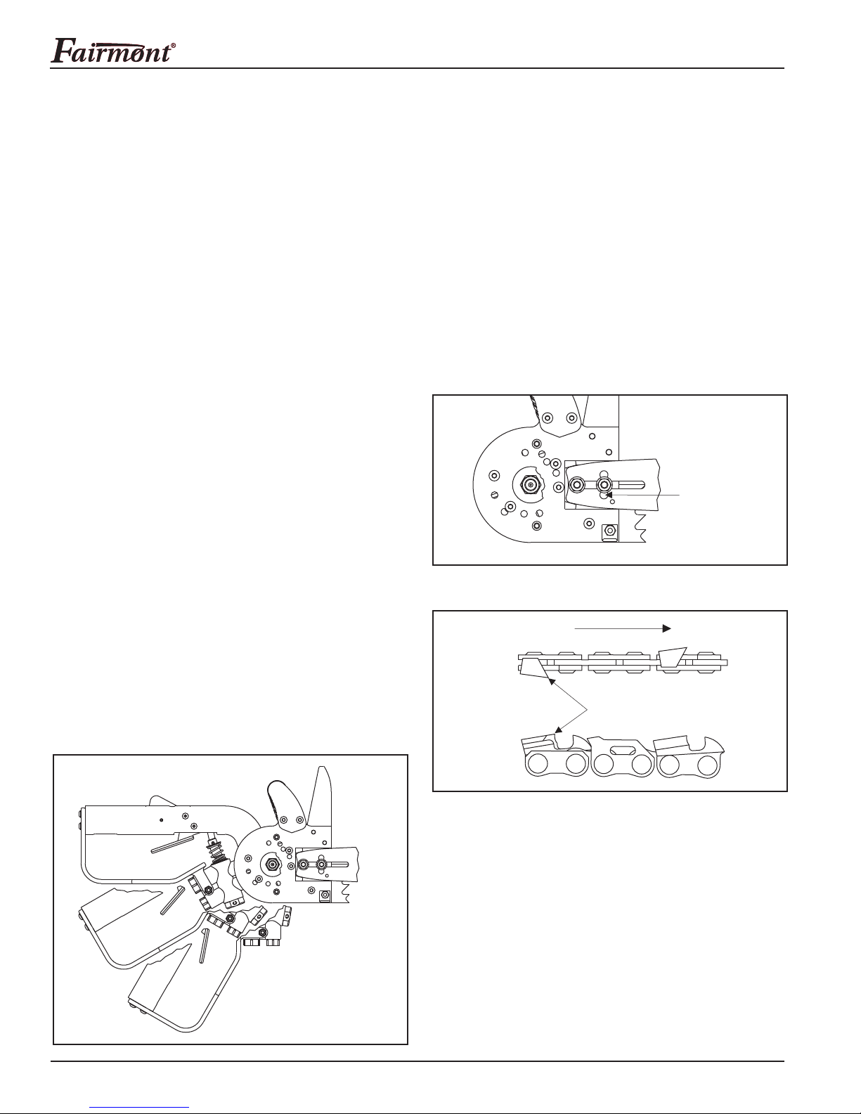
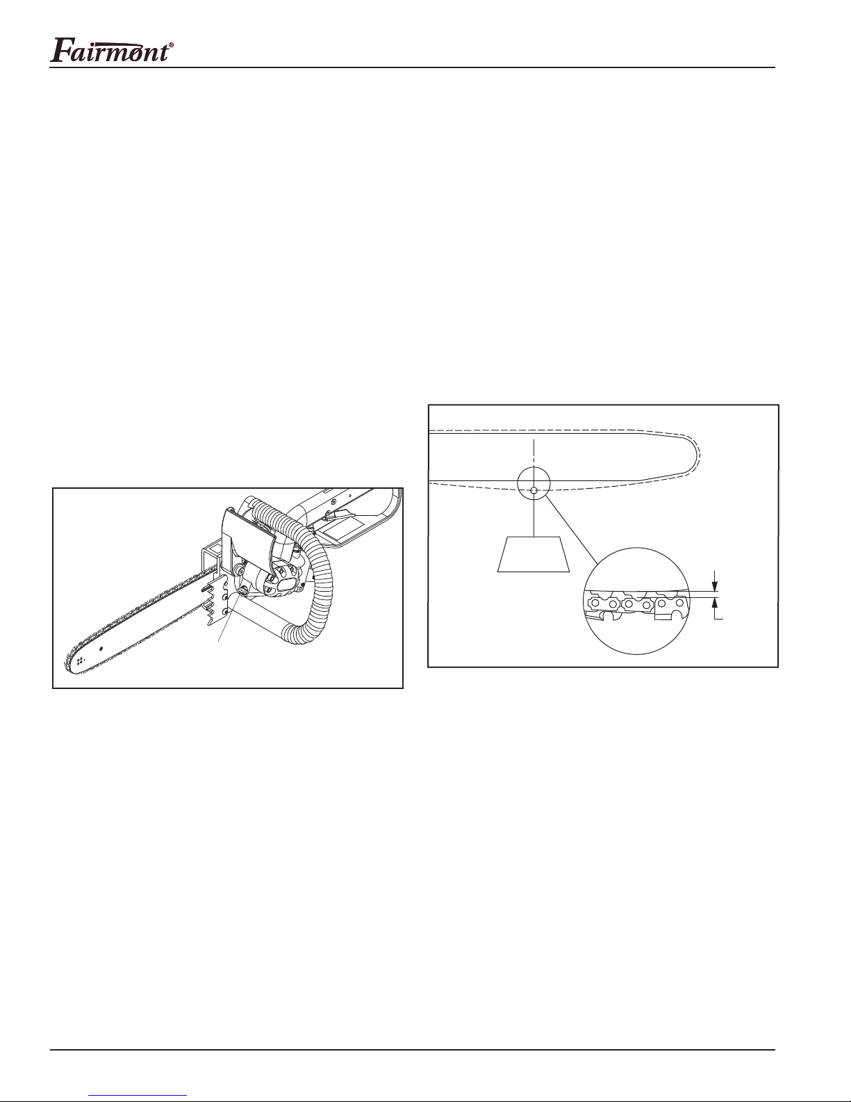
Saw Chain, Guide Bar, and Cover
1. Mark the top side of the guide bar with a grease
pencil or marker.
2. Remove the two cover knobs (53) and cover (52).
3. Loosen the two 5/16–18 ange nuts (51). Turn the
#10–24 chain adjusting screw (60) to loosen the
chain. Remove the two ange nuts (51).
4. Pull the saw chain (54) off the rim sprocket (47), and
remove the guide bar (55) and chain (54).
5. Remove the adjusting screw (60) and dog (59), if
necessary.
Rim Sprocket and Spline Adapter
Hold the rim sprocket (47), using a spanner wrench or
similar tool. Loosen and remove the 1/2" elastic stop
nut (49), washer (48), sprocket (47), spline adapter (45),
spacer (44), and Woodruff key (34).
Lower Handle and Front Handle
1. Remove one 1/4–20 x .625 button head cap screw
(43) from the rear of the lower handle (2), and
1/4–20 lock nut (4) and 1/4–20 x 1.5 button head
cap screw (3) from the front of the lower handle to
separate from the main handle.
2. Remove two 1/4–20 x .750 button head cap screws
(38) from the top of the front handle (37) and one
1/4–20 x .625 button head cap screw (43) from the
bottom of the front handle to separate from the
mount plate (40).
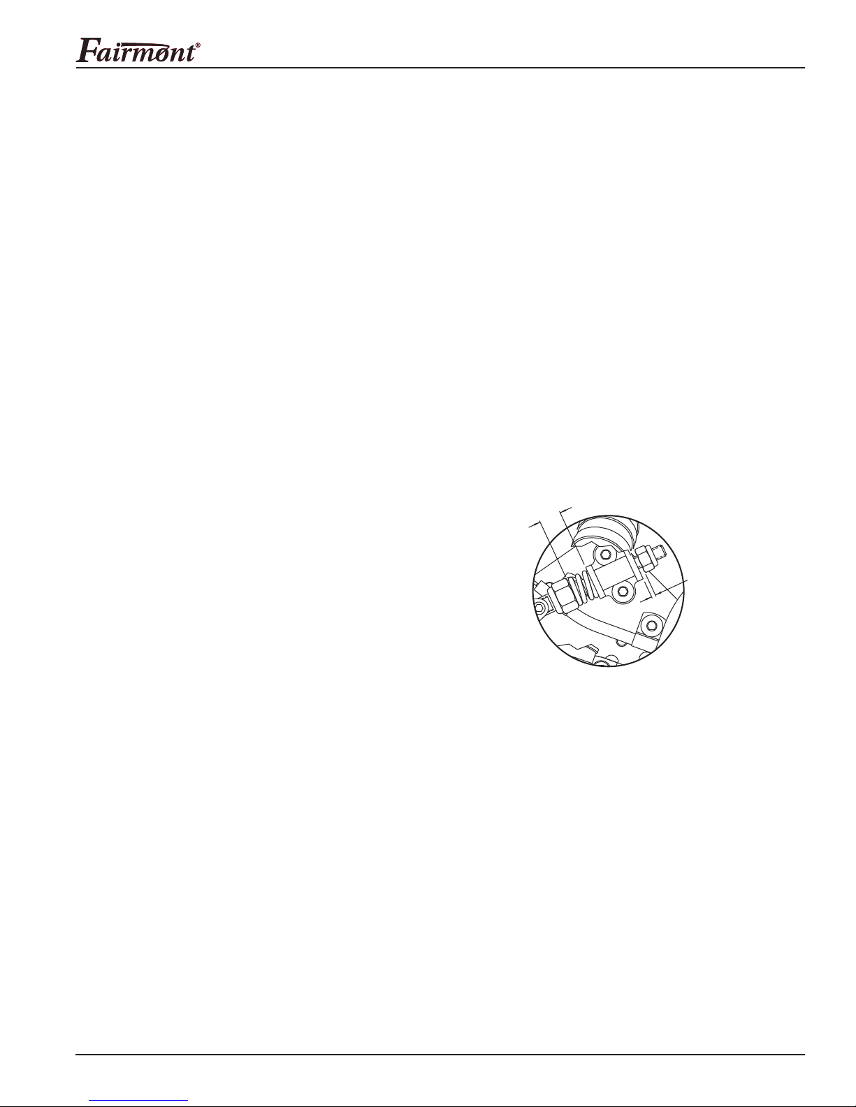
Chain Brake Assembly
1. Loosen the lock screw on the Bowden pin (68) to
ensure the cable (70) can slide easily within the pin.
Push the front shroud (39) forward.
2. Remove one #8–32 hex lock nut (76) and #8–32
screw (75) holding the toggle (74) to the rod (62).
3. Remove one .372 dia. x 1 socket head shoulder
screw (71) and separate the front shroud (39),
two washers (67), and toggle (74) from the mount
plate (40).
4. Remove one 1/4–20 hex lock nut (69) from the end
of the rod (62) and slide the rod, spring (72), and hex
lock nut (73) out of the bracket (64), only if neces-
sary. Remove two 1/4–20 x .38 button head cap
screws (66) to separate the bracket from the mount
plate.
5. Remove two 1/4–20 x .25 button head cap screws
(63) to separate the push-pull cable (70) and cable
clamps from the mount plate. Remove the cable from
the lever (81) located in the end of the spool (77).
6. Remove one #10–32 x .38 button head cap screw
(82) from the end of the spool and remove the lever.
7. Remove the retaining ring (80) from the end of the
spool and push the spool out of the spool bore.
Trigger
1. Remove one .156 dia. x 1" roll pin (9) from the
interface of the link (19) and spool (18).
2. Remove one .156 dia. x 1" roll pin (9) that holds the
trigger (20) into the main handle and remove the
trigger, only if necessary.
3. Remove one .156 dia. x .5 roll pin (10) from the
interface of the link (19) and trigger (20) to separate
components, only if necessary.
4. Remove two .156 dia. x 1" roll pins (9) from the
handle and remove the trigger actuator and spring
(12), only if necessary. Observe proper seating of
spring prior to removal.
5. Remove the washer (17) and spring (16) from the
end of the spool (18).
Control Spool and Sleeve
1. Remove the 7/8" external retaining ring (14) from the
end of the sleeve (7). Pull the sleeve and spool (18)
as an assembly out of the sleeve bore. Remove the
O-ring (13) from the inside of the sleeve bore.
2. Remove one 5/16–18 x .375 button head cap screw
(5) from the end of the spool (18). Remove the spool
(18) from the sleeve (7).
3. Remove the two O-rings (6, 8) from the sleeve;
remove the O-ring (15) from the end of the spool (18).