GreenMech EcoTMP User manual

EcoTMP
Tractor Mounted Chipper
Operator’s Manual

EcoTMP CONTENTS 1
©GreenMechLtd - 1 - 06/12
SECTION:
1. Introduction and Purpose
2. Technical Specifications, Dimensions, Noise Level, and
Lifting points
3. Safety and Symbols
3.1 Ensure!
3.2 Never!
3.3 Always!
3.4 Safety controls and switches
3.5 Control cut-outs (not applicable)
3.6 'No Stress' system
3.7 Symbols
4. Machine Preparation
4.1 Fitting to tractor
4.2 Infeed chute
4.3 Discharge chute
4.4 PTO (Power take off) Shaft length
5. Operation
5.1 Pre-work checks
5.2 Starting machine
5.3 Stopping machine
5.4 Adjustable Feed roller control
5.5 Operating Hints
5.6 Blockage Removal
5.7 Preparing for Transport on completion of work
6. Maintenance
6.1 Routine Maintenance schedule and lubrication points
6.2 Drive Belts
6.3 Drive Belt Tension
6.4 Hydraulic Connections
6.5 Steam Cleaning
6.6 Bearings and Pivots
6.7 Disc blades
6.8 Gearbox
6.9 Electrical Connections
6.10 Mountings
6.11 No Stress system
6.12 Fault finding chart
6.13 Blade sharpening

EcoTMP CONTENTS 2
©GreenMechLtd - 2 - 06/12
7. Storage
7.1 Storage
7.2 Removal from storage
8. Disposal
9. Appendix
9.1 Hydraulic Circuit
9.2 Electrical Circuits
9.3 Certificate of Conformity
9.4 Risk Assessment
9.5 Noise Assessment
9.6 Parts List
9.7 Transcript of HSE leaflet 604

EcoTMP 1. INTRODUCTION AND PURPOSE 1-1
©GreenMechLtd 1-1 04/07
INTRODUCTION
This manual explains the proper operation of your machine. Read these instructions
thoroughly before operating and maintaining the machine. Failure to do so could result in
personal injury or equipment damage. Consult your GreenMech supplier if you do not
understand the instructions in this manual.
CAUTION! This symbol indicates important safety messages in this
manual. When you see this symbol, be alert to the possibility of injury to
yourself or others, and carefully read the message that follows.
We recommend that you keep this manual with the machine in the box provided. Note
here the serial number and quote it in any communications. This is important when
ordering spares. Remember to include all numbers and letters.
VIN Number:…….…………………………
Serial Number:….…………………………
Write in the number!
This manual covers the following model.
EcoTMP tractor mounted chipper
Note: Normal build infeed chute position is Left Hand side (nearside) of tractor. This can
be changed to Right Hand side by factory fitted reversal of the gearbox.
The information in this manual is correct at the time of publication. However, in the
course of development, changes to the machine specification are inevitable. Should you
find any information to vary from the machine in your possession please contact your
GreenMech dealer for up to date information.
The manual may contain standard and optional features and is not to be used as a
machine specification.
PURPOSE
CAUTION! This machine is designed solely to chip wood and must not be
used for any other purpose. The machine should only be used by trained
operators who are familiar with the content of this instruction manual. It is
potentially hazardous to fit or use any parts other than genuine GreenMech
parts. The company disclaims all liability for the consequences of such use,
which in addition voids the machine warranty.
S/N EcoTMP
Serial Number plate

EcoTMP 2. SPECIFICATIONS 2-1
©GreenMechLtd 2-1 04/07
TECHNICAL SPECIFICATION EcoTMP
Max Capacity 150mm (6-inches)
Chipping Disc 500mm x 25mm (19.86 x 1.01inch)
Speed 2600 rpm
Chipping Blades 2 Discs
Feed Rollers 2 x Hydraulic
Power Control No-Stress Electronic Feed Roller Controller
Power Unit Tractor 25-45hp (see below)
Length (Transport) 2320mm
Width 1060mm
Height 2130mm
Weight 487Kg
Fig 2.1 EcoTMP Main Features
PTO connection
Infeed Chute catch
Discharge chute
Chipper disc cover
Infeed chute
Control bar
Feed roller pivot
3 Point hitch
Reset bar
Gearbo
x
Legs
Tractor hoses & cable

EcoTMP 2. SPECIFICATIONS 2-2
©GreenMechLtd 2-2 04/07
Noise
Noise levels vary depending on type of material being processed. Also duration of
operation is variable. Noise emission tests have been carried out and the guaranteed
sound power level is displayed on the CE plate as follows: Lwa 120dba
Minimise noise by switching to idle or stopping the tractor engine whenever chipping is not
in progress.
To reduce tractor noise level, optional 1000rpm PTO speed may be selected provided
tractor engine speed is reduced by approximately 50% accordingly.
CAUTION! Do not operate above 540rpm.
Full details are included in the Risk Assessment in the Appendix.
CAUTION! Operators must wear appropriate ear protection. Bystanders must be
kept away from proximity of machine.
Lifting Points
There are three lifting points by the chipper disc cover.
Tractor requirement
25 – 40HP at 6 spline 540rpm PTO shaft with provision for 22 litres/min (4.8 gall/min) at
172 bar (2500 lbf/in2) continuous flow remote oil supply and trailer light socket for No
Stress system.

EcoTMP 3. SAFETY 3-1
©GreenMechLtd 3-1 04/07
3.1 ENSURE:
3.1.1 All Operators must be fully trained in
the use of their machine.
(Certificated Operator training courses are
available on request.)
3.1.2 The Operators Manual is read and
understood.
3.1.3 The enclosed HSE guidance notes
are read and understood.
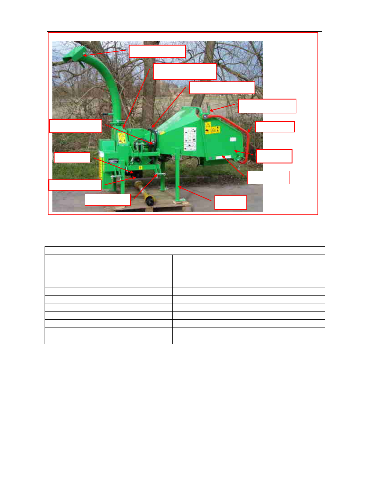
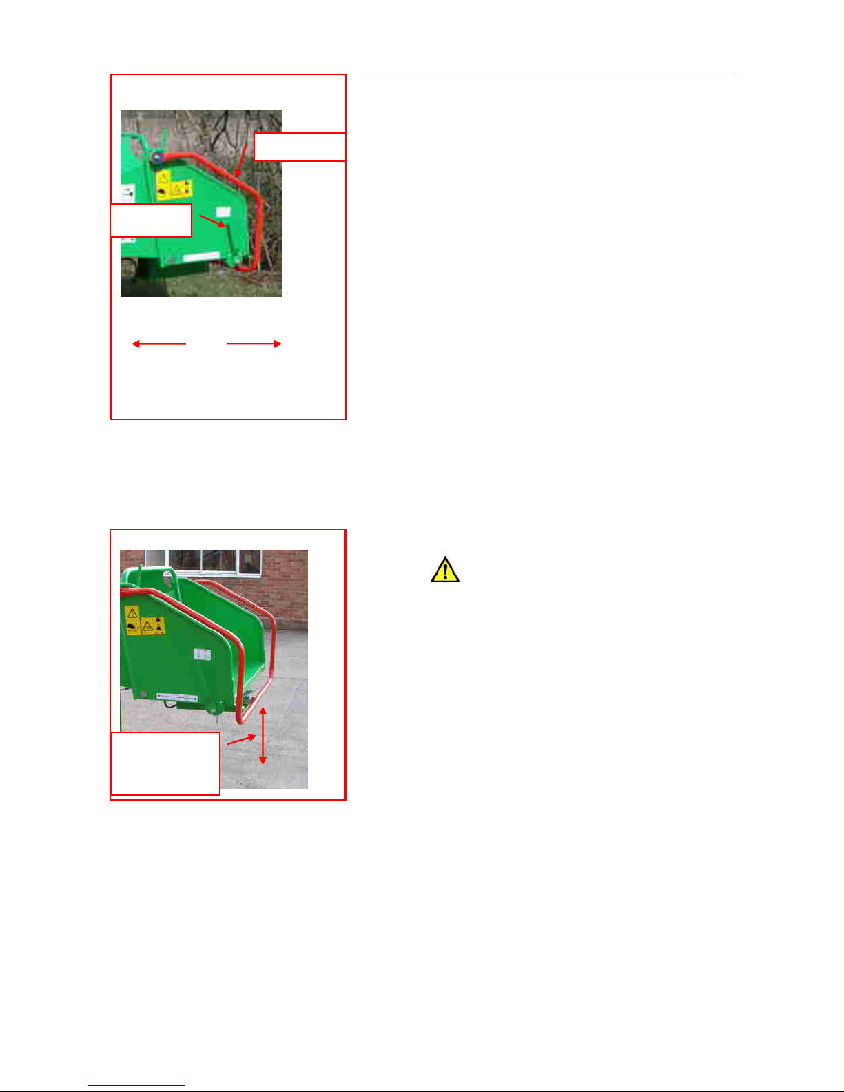
3.1.4 The machine is positioned on level
ground and the machine must be level with
the infeed chute at no less than 600mm
(23.62 inches) above ground level (fig
3.4.3).
3.1.5 not applicable
3.1.6 All guards are fitted and in good
condition.
3.1.7 Blades are in good condition and
secure.
3.1.8 All blades are sharpened or replaced
in “Sets”.
3.1.9 All fasteners are checked regularly
for tightness.
3.1.10 Only “WOODEN” materials free of
nails etc., are fed into the machine.
3.1.11 Correct First Aid Kit including large
wound dressing is available on site.
3.1.12 Fire extinguisher is available on site.
3.2 NEVER:
3.2.1 Work on the machine until the
chipper disc is stationary and engine or
PTO has stopped.
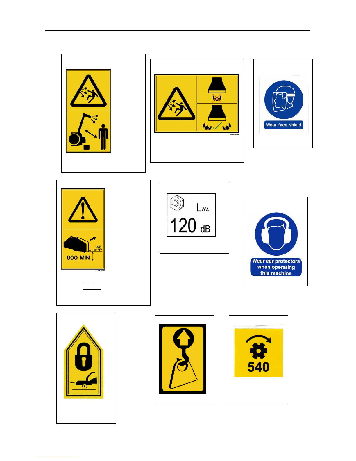
3.2.2 Operate the machine without
protective clothing (Eye protection,
Earmuffs, and Gloves), or high visibility
clothing when working on roadside.
3.2.3 Operate with loose articles of
clothing, including loose cuffs on gloves.
3.2.4 Work under a raised component
without adequate safety support.
3.2.5 Operate the machine with untrained
personnel or with individuals present who
are not involved in the chipping operation.
3.2.6 Leave the machine unattended with
engine running at full operating speed.
(See section 4)
3.2.7 Put any part of your body into the
infeed chute while the machine is running.
3.2.8 Operate the machine whilst under the
influence of alcohol or drugs.
3.2.9 Operate inside a building or confined
space.
3.2.10 Climb on the infeed chute.
3.3 ALWAYS:
3.3.1 Check machine before starting (see
Section 4 Preparation and Section 5.1
Operation: Pre-work checks).
3.3.2 Be aware of potential hazards in the
work area, i.e. uneven ground, tree roots,
trip/slip hazards, obstructions and type of
materials being fed into the machine.
3.3.3 Feed from the side.
3.3.4 Have a second trained operator
within easy reach of the machine.
3.3.5 Maintain strict discipline at all times.
3.3.6 Service machine at specified periods.
(see Section 6: Routine Maintenance).
3.3.7 Note direction of discharge chute and
if necessary note the wind direction to
prevent debris from being blown into
highway or where it could affect members
of the public.
3.3.8 Remove key before doing any
maintenance.

EcoTMP 3. SAFETY 3-2
©GreenMechLtd 3-2 04/07
3.4 Safety Controls and Switches
3.4.1 Emergency Stop/Control Bar (fig
3.4.1)
In the event of an emergency, push the
emergency stop bar to STOP the feed
rollers. This will lock in position.
3.4.1.1 Once the emergency has been
rectified the following sequence should be
carried out:
3.4.1.2 To restart rollers pull the reset
lever, the control bar can then be returned
to the Feed In position.
3.4.1.3 Should the stop bar be tripped
accidentally in normal working conditions
i.e. NOT an emergency, then the rollers can
be recovered by performing the above
sequence.
3.4.1.4 To reverse the rollers (feed out)
push the control bar into the middle detent.
To regain forward (feed in) pull the control
bar away from the chipper. It is not
necessary to use the reset bar.
3.4.2 PTO stop
3.4.2.1 To stop the PTO use the tractor
control or tractor engine stop.
CAUTION! Do not restart until hazard
has been removed.
3.5 Control cut-outs
Not applicable for tractor mounted model
3.6 No Stress system
3.6.1 Speed sensor disables feed roller
FEED IN or FEED OUT mode when engine
speed is below factory pre-set value.
Fig 3.4.1 Control Bar and Reset
Lever
Control Bar positions
(Nearside)
STOP FEED OUT FEED IN
FEED IN FEED OUT STOP
(Offside)
Reset bar
Control bar
Fig 3.4.3 Infeed chute height
Infeed chute
height 600mm
min. (24")

EcoTMP 3. SAFETY 3-3
©GreenMechLtd 3-3 04/07
3.7 SYMBOLS on the MACHINE
These relate to operator safety, correct use and maintenance of machine. Check that all
personnel understand and are familiar with meanings before using the machine.
Important Safety symbols
Take the correct action shown on the display below the stated hazard (see table)
Important Operating Checks Notice
Before use carry out daily the stated checks in the order shown (see table)
Caution! Remove key
Do NOT
start engine
Caution!
Beware
flying
object
hazard
Beware
noise
hazard
Beware
trapping
hazard
Brakes
off
-incorrect
Read
instruction
manual
Wear
helmet &
visor
Wear ear
protectors
Wear
proper
clothes
Brakes
on
-correct
Machine
not level
-incorrect
Beware
flying
object
hazard
Beware
flying
object
hazard
Beware
exposed
drives
hazard
Caution!
Machine
level
-correct
Keep
bystanders
away
Position
and lock
discharge
chute
Fit all
guards Keep
nuts tight
Every 8 Hours –
Daily checks Remove key
stop engine
1. Check
coolant level 2. Check engine
oil level
3. Check
hydraulic oil
level
4. Check
machine is level 5. Check brakes
are on
6. Check
chipper disc is
clear of debris
7. Check all
guards are in
place
8. Check infeed
chute is clear of
debris
9. Lock
discharge chute
10. Pull control
bar to work
position 11. Start engine 12. Increase
from Idle to Run
General Safety
Daily Checks

EcoTMP 3. SAFETY 3-4
©GreenMechLtd 3-4 04/07
Important Safety Information
Sound level
Ear defenders must be
worn
Caution! Beware of thrown
object hazard
Action: Keepaway from fast
discharge chute
Caution! Beware of thrown
object hazard
Action: Stand to side of infeed
chute, NOT in centre.
Caution!
Do NOT operate with infeed
chute at less than 600mm from
ground (bottom bar machine).
Transport Lock
Lock this
component before
moving machine
Lift Point
PTO Direction
Face shield must
be worn
Ear defenders must
be worn

EcoTMP 3. SAFETY 3-5
©GreenMechLtd 3-5 04/07
Maintenance Information
Operating Information
Grease point
40 hours / weekly
Reset lever: Left hand shown
Push to stop : Pull to reset
Control Bar (bottom bar). Left hand shown
Push to stop: Centre-feed out: Pull–feed in
Discharge chute control
Green is UP: Blue is DOWN
High temperature
Grease 40 hours

EcoTMP 4. MACHINE PREPARATION 4-1
©GreenMechLtd 4-1 04/07
4.1 Fitting to tractor
4.1.1 Remove the top, and lower linkage
pins on the chipper (fig 4.1.1)
4.1.2 Lower the three-point linkage on the
tractor and reverse up to the chipper.
4.1.3 Locate the two lower linkage pins
through the lower arms and the chipper
frame.
4.1.4 Secure the pins with the clips
provided.
4.1.5 Adjust the top link to the correct
length and locate the linkage pin through
the frame and arm, secure with the clips
provided.
4.1.6 Switch off the tractor engine.
4.1.7 Check that the PTO shaft is the
correct length for the tractor make and
model. See section 4.4 below
CAUTION! The PTO shaft is equipped
with shear bolt protection and this end of
the shaft MUST be fitted to the tractor PTO
shaft. (Pictograms stamped on PTO shaft
cover may be incorrect.)
4.1.8 Depress the two spring buttons and
slide onto the tractor shaft until the buttons
spring out into the correct locations.
4.1.9 Depress the single spring button on
the ratchet clutch end and slide onto the
chipper gearbox shaft until the button
springs out into the correct location.
4.1.10 Connect up the hoses to the tractor
remote supply. (fig 4.1.2)
4.1.11 Connect the cable to the trailer
socket on the tractor.
4.1.12 Turn on the tractor’s sidelights to
provide power for the No-Stress system.
CAUTION! Check that the discharge
chute does not hit the tractor cab when the
chipper is lifted up.
CAUTION! Do not operate the
machine when not fully attached to the
tractor
4.1.13 Unfold infeed chute as 4.2 below.
4.1.14 Start tractor engine slowly and
check PTO. operation.
Fig 4.1.2 Tractor hoses and cable
Electric plug
Hoses
Fig 4.1.1 3 Point links and PTO shaft
Top link pin
Lower link pins
PTO Shaft

EcoTMP 4. MACHINE PREPARATION 4-2
©GreenMechLtd 4-2 04/07
4.2 Infeed Chute
4.2.1 Remove the transport pin for the
infeed chute catch, release the catch (fig
4.2)
4.2.2 Using the tubular edge as a handle,
lower the infeed chute to the work position
and reset the catch.
4.2.3 Measure the height of the infeed
chute and adjust stands as required.
4.2.4 Pull the reset lever to release the
control bar for use.
CAUTION! The infeed chute must not
be used at less than 600mm from the
ground. (fig 3.4.2).
CAUTION! Before travelling, always
fold up and secure the infeed chute.
4.3 Discharge Chute (Fig 4.4)
4.3.1 Release the swivel clamps, point the
chute in the desired direction and tighten
the clamps.
4.3.2 Set the flap at the desired height and
tighten the clamp.
CAUTION! Lock the discharge chute
in the rearward position when travelling.
4.4 PTO shaft length
The PTO shaft must overlap by 150mm in
longest situation and not bottom out in
shortest situation. Always follow
instructions supplied with shaft if available.
4.4.1 To shorten PTO, separate each
section and refit to machine.
4.4.2 Raise machine on linkage until
shortest length is achieved.
4.4.3 Supporting the two sections side by
side, mark a point 25mm - 50mm back from
where the guard tube meets the joint guard
onto the other section. Repeat for the
opposite end.
4.4.4 Adjust the tractor linkage to set at
longest shaft length.
4.4.5 Check that 150mm minimum overlap
of sections is achieved between marks.
4.4.6 Saw off the surplus guard and shaft
at each mark and remove cuttings and
burrs.
4.4.7 Grease the shaft, reassemble to
machine, and test before use.
Fig 4.2 Infeed chute catch
Catch (transport)
Catch
(work)
Fig 4.3 Discharge Chute
Swivel clamps
Flap lever

EcoTMP 5. OPERATION 5-1
©GreenMechLtd 5-1 06/12
5.1 Pre-Work Checks:
5.1.1 Check tractor is stationary, engine
turned off and hand brake applied.
5.1.2 With machine held on tractor linkage,
set support legs approximately (fig 5.1.1).
5.1.3 Lower linkage, check that machine is
level and infeed chute is greater than
600mm from ground (fig 3.4.3).
5.1.4 Check fasteners for tightness and
hydraulic connections for leaks.
5.1.5 Check condition of disc blades.
5.1.5.1 Check nothing is rotating.
5.1.5.2 Remove the 1 bolt retaining chipper
disc cover (fig 5.1.2).
5.1.5.3 Using discharge chute handle as a
lever, swing back cover on to stop to
expose chipper disc and blades.
(fig 5.1.2)
5.1.5.4 Carefully rotate chipper disc to
check tightness of disc blade bolts and
condition of blades.
5.1.5.5 Remove any loose wood material.
5.1.5.6 If any bolts are loose, refer to
maintenance section for further action.
5.1.5.7 Replace chipper disc cover and
tighten bolts securely.
5.1.6 Check discharge chute is in desired
position and all clamps are tight. (see
Section 4.3)
5.1.7 Check infeed chute flap is lowered.
5.1.8 Check work area and erect signs
and cone off discharge area if necessary.
5.1.9 Check ALL safety procedures have
been followed.
CAUTION! Remember to raise infeed
chute flap and the chipper on the tractor
linkage before driving off.
Fig 5.1.1 Support Legs
Support Legs (4)
Fig 5.1.2 Chipper Disc Cover
Disc Cover
locating bolt

EcoTMP 5. OPERATION 5-2
©GreenMechLtd 5-2 06/12
5.2 Starting Machine:
5.2.1 Check all other personnel are clear
of machine.
5.2.2 Check that feed roller control bar is
pushed to the FEED OUT or STOP
position, to make the machine safe.
5.2.3 Start the tractor.
5.2.4 Engage PTO to start the chipper.
Check lights are ON.
5.2.5 Increase the speed to operating
speed (PTO 540 rpm), when No Stress light
goes Green.
Note: When used with larger tractors
having 1000 rpm PTO option, this may be
selected to enable use of slower engine
speed to reduce noise level and fuel
consumption. Always ensure that the No
Stress light remains Green.
5.2.6 Pull the reset lever to release the
control bar for work.
5.3 Stopping Machine
5.3.1 Push the control bar to STOP
position.
5.3.2 Disengage tractor PTO.
5.3.3 Stop tractor engine.
5.3.4 Wait for chipper disc to stop.
CAUTION! The chipper disc will take
several seconds to stop due to its inertia.
5.4 Adjustable Speed Feed Roller
Control
When chipping wood sizes larger than
120mm diameter it may be necessary to
reduce the feed roller speed to suit the
material being chipped.
5.4.1 Turn the valve control knob (fig 5.4)
clockwise until valve is closed.
5.4.2 Turn the knob anticlockwise to the
recommended setting in the table.
Fig 5.4 Adjustable feed roller control
Control knob settings
Material Setting
up to 120mm Fully open (3 turns)
120 - 150mm 1/2 to 3/4 turn
Control Knob

EcoTMP 5. OPERATION 5-3
©GreenMechLtd 5-3 06/12
5.5 Operating Hints
5.5.1 Check that chipper disc is at full
speed with NO Stress light Green.
NOTE: The “No Stress” system will only
allow FEED IN (Forwards) and FEED OUT
operation of the feed rollers when the
machine is running at FULL operating
speed.
5.5.2 Reduce the chipper speed to IDLE
whilst further material is collected for
chipping.
5.5.3 Take care when feeding wood into
the machine to allow for awkward shapes to
“KICK” when contacting the feed rollers.
5.5.4 Position the end of larger sections of
wood inside the infeed chute and then
support the other end whilst pushing the
wood into the feed rollers.
CAUTION! Do not release discharge
chute clamps when chipping is in progress.
Elevation of the discharge is altered by
means of the adjustable flap (fig. 4.4).
CAUTION! Keep working area around
the machine clear at all times and check
only authorised personnel are present.
5.6 Blockage Removal
5.6.1 Stop tractor engine and disengage
p.t.o. shaft. See Section 5.2.
5.6.2 Open chipper chamber See Section
5.1 (Fig 5.1.2).
CAUTION! Chipped material is
inflammable. Expect large volume and
prevent from falling into engine
compartment. All material must be
removed.
5.6.3 Rotate discharge chute to accessible
position for cleaning.
5.6.4 Clean out discharge chute thoroughly
with a suitable rod to pass around bends as
necessary.
Fig 5.6 Chipper covers
Chipper
cover
Feed roller
cover

EcoTMP 5. OPERATION 5-4
©GreenMechLtd 5-4 06/12
5.6.5 Check if chipper disc is free to rotate.
Pull top of disc in operating direction of
rotation. If so proceed to 5.6.11 below.
CAUTION! Beware sharp edges of
blades and unexpected movement of disc
due to resistance of engine.
If disc does NOT rotate freely, proceed as
follows:
5.6.6 Remove feed roller cover (Fig 5.6) to
access chipper blades and shear bar.
5.6.7 Carefully remove excess loose material
from around chipper disc and note any
obstructions.
5.6.8 Carefully rotate chipper disc in reverse
direction (top away from operator) by full
revolution to release blocked material. Use bar
against paddle blades for aid.
5.6.9 Carefully remove all material, checking
for obstructions. Check rotation of chipper disc.
5.6.10 Check condition of blades.
Note: Always attempt to find reason for
blockage. e.g. blunt blades, slack drive belts.
5.6.11 Re-assemble all covers with correct
fasteners and check for security.
5.6.12 Start machine (See 5.2) and check
operation.
Note: If machine will not run repeat process or
contact dealer for technical advice.
CAUTION! Beware sharp edges of
blades and unexpected movement.
5.7 Preparing For Transport On
Completion Of Work (fig 5.7)
5.7.1 Check that engine has stopped and
chipper disc is stationary.
5.7.2 Remove surplus material from infeed
chute and machine surfaces.
5.7.3 Lift up infeed chute to transport
position, secure with lock and fit locking pin.
5.7.4 Set discharge flap into lowest
position and tighten clamp.
5.7.5 Release clamps, turn discharge
chute to rearward position away from cab,
tighten clamps.
5.7.6 Raise machine on tractor linkage.
5.7.7 Raise support legs and secure if
transporting on rough terrain.
Fig 5.7 Chutes ready for transport
(except legs)
Infeed chute
folded

EcoTMP 6. MAINTENANCE 6-1
©GreenMechLtd 6-1 04/07
ROUTINE MAINTENANCE SCHEDULE
CAUTION! Always stop tractor, remove key and check for rotation before carrying out
any maintenance.
Action Section Page
DAILY
Check drive belt 6.2 6-3
Check condition of disc blades and retaining bolts 6.7 6-4
Check feed roller control bar function 3.4 3-2
First 50 hours
Check drive belt tension 6.3 6-3
Check hydraulic connections 6.4 6-3
Check all mountings 6.10 6-5
Check feed roller control bar function 3.4 3-2
Weekly in addition to Daily actions
Check drive belt tension 6.3 6-3
Steam clean machine 6.5 6-3
Check electrical connections 6.9 6-5
Check feed roller control bar function 3.4 3-2
Grease all bearings and pivots 6.6, 6.1 6-3
Check hydraulic connections 6.4 6-3
Check gearbox oil level 6.8 6-5
Check PTO shaft Refer to supplier instructions
Check all mountings 6.10 6-5
250 hours in addition to Daily and Weekly actions
Check condition of bearings and pivots 6.6 6-3
1000 hours in addition to 250 hour actions
Drain gearbox oil 6.8 6-5
Recommended lubricants Specification
Gearbox Oil EP90
Grease Complex grease EP2 (high temperature)

EcoTMP 6. MAINTENANCE 6-2
©GreenMechLtd 6-2 04/07
6.1 Lubrication Points (see 6.14)
Grease except where stated
6.1.1 PTO shaft 2 nipples
6.1.2 Top Feed roller pivot 1 nipple
6.1.3 Top Feed roller bearing 1 nipple
6.1.4 Chipper Disc front bearing 1 nipple
6.1.5 Chipper Disc rear bearing 1 nipple
6.1.6 Labyrinth seal 1 nipple
6.1.8 Infeed chute hinges Oil
6.1.9 Mechanical reset mechanism Clean and grease
6.1.10 Bottom Feed roller bearing 1 nipple
Note. Do not overgrease bearings as damage to seals may occur.
Note: Use high temperature grease on chipper disc bearings.
Fig 6.1.2 Grease nipples (Opposite side)
Nipple
6.1.5
Nipple
6.1.6
Fig 6.1 Lubrication points EcoTMP
6.1.1
6.1.5
6.1.4
6.1.3
6.1.9
6.1.2
6.1.8
6.1.10

EcoTMP 6. MAINTENANCE 6-3
©GreenMechLtd 6-3 04/07
6.2 Drive Belts
6.2.1 Remove belt guard (fig 6.2) and
check belts daily, before work.
6.2.2 Replace Guard before use.
6.3 Drive Belt Tension
The belt is tensioned by a screw under the
machine to set the gearbox mounting (fig
6.3).
6.3.1 Loosen nut and adjust bolt to tension
belts.
6.3.2 Tighten nut.
6.4 Hydraulic connections
50 hours
6.4.1 With the aid of the circuit diagram to
follow the hose routings, check all hoses
and connections for leaks and damage.
6.4.2 Replace any worn or damaged
hoses with the correct type and length.
6.4.3 Before removal, check routing and
ensure replacement hose is fitted free of
strains, twists or kinks.
CAUTION! Ensure any residual
pressure is released before dismantling.
CAUTION! Ensure hoses are refitted
free of twists and kinks.
6.5 Steam Cleaning
weekly and every 250 hours
6.5.1 Check all covers are fitted and
closed
6.5.2 Steam clean machine surfaces.
6.5.3 Clean electrical components with a
damp rag, spray with WD40 and then wipe
with dry rag.
CAUTION! Do not steam clean
directly on to electrical components, e.g.
control boxes.
6.6 Bearings and Pivots
Weekly
See paragraph 6.1 for routine lubrication.
250 hours
6.6.1 Check rotating components for
excessive movement and noise in
operation.
6.6.2 Replace as required.
Fig. 6.2 Drive Belt Guard
Belt Guard
Fig. 6.3 Belt Tensioner
Belt
Tensioner
Other manuals for EcoTMP
1
Table of contents
Other GreenMech Chipper manuals
Popular Chipper manuals by other brands

Wallenstein
Wallenstein BXT52S Setup instructions

Split-fire
Split-fire 4090 owner's manual

Hyundai power products
Hyundai power products HYCH6560 user manual

Billy Goat
Billy Goat Termite KD512SP Operator owner's manual

Echo
Echo Bear Cat 76824 Faq

Spartan Equipment
Spartan Equipment 75594 Operator and parts manual

Timberwolf
Timberwolf TW 230HB instruction manual

hillvert
hillvert HT-HECTOR-100B user manual

Yamaha
Yamaha GTS1000MZ user manual

Wallenstein
Wallenstein BXC34 Operator's manual

TruYard
TruYard CM65 Series Safety, operation & maintenance instructions

GXi Outdoor Power
GXi Outdoor Power Brush Master owner's manual