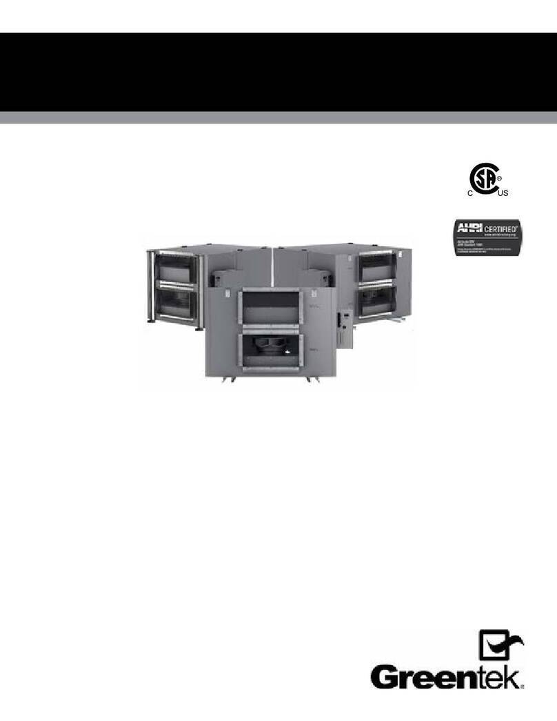
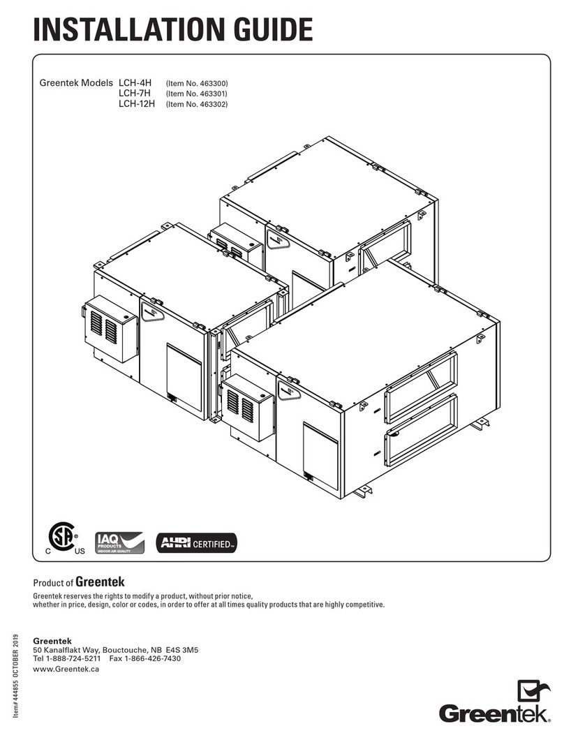
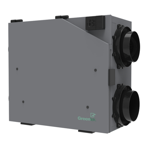
Greentek HRV Series Assembly instructions

HOME OWNERS GUIDE
RESIDENTIAL USE ONLY
HRV MODEL
PH 7.15, RNC1.5
PH 10.22, RNC2.0, RNC2.0ES
XDH 7.15 HRV
C3.14, RNC1.0, RNC12
SS 3.80
SOLACE, XPH1.5, XPH2.0
ERV MODEL
PE 7.15
PE 10.22
SS 3.80
Product of Greentek
Greentek reserves the rights to modify a product, without prior notice,
whether in price, design, color or codes, in order to offer at all times quality products that are highly competitive.
Greentek
50 Kanalflakt Way, Bouctouche, NB E4S 3M5
1-888-724-5211 Fax 1-866-426-7430
www.Greentek.ca
Item#463674 SEPT2018

Page 2
IMPORTANT - PLEASE READ MANUAL BEFORE INSTALLATION
CONTENTS
TO REDUCE OR AVOID THE HAZARDS OF ELECTRIC SHOCK AND FIRE:
CAUTIONS CONCERNING THE OPERATION AND FULL EFFICIENCY OF THIS PRODUCT:
CAUTION: Do not install in a cooking area or connect directly to any appliance. Turn off all integral disconnects before servicing.
NOTICE:
Prior to installing, serious consideration must be taken to insure this ventilation system will operate properly if integrated to any other type
of mechanical system, i.e. a forced air system, or an air handling unit. To insure proper operation & compatibilities of both system, it is required that the
airflow’s of the Heat Recovery Ventilator (HRV) or Energy Recovery Ventilator (ERV) be balanced, by following the procedures found in this manual.
The way that your Heat/Energy-recovery ventilator is installed may make a significant difference to the electrical energy that you will use. To
minimize the electricity use of the Heat/Energy-recovery ventilator, a stand-alone fully ducted installation is recommended. If you choose a
simplified installation that operates your furnace airhandler for room-to-room ventilation, an electrically efficient furnace that has an electronically
commutated (EC) variable speed blower motor will minimize your electrical energy consumption and operating cost.
LIMITATIONS: The product is for residential applications only. Must be installed in accordance with all national and local regulations, building and
safety codes.
SECTION PAGE
1. Operations & Main Fonctions. . . . . . . . . . . . . . . . . . . . . . . .3
2. Types of Installations . . . . . . . . . . . . . . . . . . . . . . . . . . . .3
3. Description of your Ventilation System . . . . . . . . . . . . . . . . . .4
4. Operation of the DuotrolTM System . . . . . . . . . . . . . . . . . . . .5
5. Operation of your Wall Controls . . . . . . . . . . . . . . . . . . . . 6-11
6. Troubleshooting. . . . . . . . . . . . . . . . . . . . . . . . . . . . . . .12
7. Maintenance. . . . . . . . . . . . . . . . . . . . . . . . . . . . . . . . .12
8. Warranty . . . . . . . . . . . . . . . . . . . . . . . . . . . . . . . . . . .13
• Before servicing or cleaning the HRV system, always remove the
power cord from the AC wall outlet.
• To reduce the hazards of electric shock or fire, do not perform any
service to the HRV system other than those stated in the operating
manual instructions.
• To reduce the risk of electric shock, this ventilation system (HRV/ERV)
comes equipped with a 3-prong plug-in. This plug will fit in a polarized
outlet only one way.
• Do not use ventilation system for outdoor application.
• Do not pull or twist power cord when disconnecting it from the
ventilation system. Grasp the plug firmly, not the cord.
• Do not modify the power plug in any way; if modified, risk of electric
shock fire or even damage to the unit may occur.
• Do not use the ventilation system for removal of flammable fumes,
gases or connect directly to any appliances.
• Use a dedicated AC 120V outlet only.
• Do not obstruct or cover the air intake or air outlet of the ventilation
system.
• Do not modify, repair or disassemble this system. These tasks are to
be performed by authorized serviced personnel only. Fire, electrical
shock and/or bodily injury may occur if these warnings are not
followed.
• To prevent injuries, do not operate the ventilation system, while
servicing or maintaining. There are impeller wheels turning at a very
high speed that must fully stop rotating prior to accessing the inside of
the unit.
• Always assess the operation of the ventilation system on how it may
interact with vented combustion equipment (ie. Gas Furnace, Oil
Furnace, Combustion, Appliances, etc.)
• Do not use for swimming pool/spa applications.

Page 3
1. OPERATION & MAIN FUNCTIONS
2. TYPES OF INSTALLATIONS
Your ventilation system has been engineered & designed to improve your indoor air quality by reducing during the winter time, excess humidity or
other contaminants in your home and replacing this air by fresh filtered air from the outdoors. During colder seasons, the units heat recovery core
(polypropylene core) will reclaim the heat from the outgoing stale air and use this heat to temper the incoming fresh air, which reduces the cost of
effectively ventilating your home during winter.
NOTE:
Reverse process occurs in the summer months.
Fresh air
Exhaust air
Bathroom
Control
Forced air system
HRV/ERV
Exhaust air hood
Fresh air supply hood
Exhaust
and supply
in the return
Bathroom
Control
Forced air system
HRV/ERV
Exhaust air hood
Fresh air supply hood
Exhaust at the
source and
supply in
the return
Bathroom
Control
HRV/ERV
Exhaust air hood
Fresh air supply hood
Independent
system
Best
Better
Good

Page 4
3. DESCRIPTION
VENTILATION SYSTEM
PH, PE, Solace, XPH1.5, XPH2.0, RNC1.5, RNC2.0 & RNC2.0ES
Side View
VENTILATION SYSTEM WITH RECIRCULATION MODE
MODEL XDH
Side View
COMPACT VENTILATION SYSTEM
Front View
• Fresh Air from Outside Port A:Inlet for fresh outdoor air.
• Exhaust Air to Outside Port B:Outlet for exhausting stale,
humid & contaminated air to the outdoors after transferring its heat to
the recovery core.
• Exhaust Air From Home Port C:Exhausts stale, humid &
contaminated air to the outside from multiple location of the home or
from the return air of the forced air system, prior to passing threw the
heat recovery core. Ex: Bathroom, laundry room etc.
• Fresh Air to Home Port D:Introduces & distributes clean & fresh
air to your home. The homes fresh air ports are normally installed
in the main living areas or in the return/supply duct of the forced air
system. Ex: Living room, bedrooms, recreation rooms etc.
• 5th Port on XDH Models only E:
Re-circulating port during
defrost sequence, or with specific wall control Vectra EHC1.5, (RD-3D &
RD-4D) Re-circulation mode can be chosen. (Ref. The Installation Guide)
• DuotrolTM Systems: Selects your ventilation modes
(OFF, CONT or INTER), also to adjust your continuous airflow rates:
Increasing (+)/Decreasing (-).
• German Engineered Motors(2): Designed with high performance
and reliability, they are maintenance free for your comfort and peace
of mind.
• Synthetic Filters: Capture the largest particle & protects your heat
recovery core from potential obstruction by these particles.
• Heat Recovery Core:
A polypropylene cross-flow type it is
designed to transfer the heat between both exhaust & supply air
streams without allowing any contamination or mixing of both air
streams to maximize the efficiency and improves your indoor air quality.
*Ideal for cold climates.
• Energy Recovery Core: An energy recovery core transfers latent
energy (humidity) & heat from one airstream to the other without
mixing the airstreams for maximum efficiency and improves your
indoor air quality.
*Ideal for warm humid climates.
• Condensate Drain Pan & Drainage Hose: Captures the water
that accumulates during the heat transfer and defrosts sequence in
the fall, winter & early spring seasons. Drain hose is connected to the
drain pan and serves as drainage for the accumulation of water. It is
normal during summer months to find no condensation in drain pan or
in drainage hose.
• Automatic Defrost Sequence: The defrost sequence is
electronically controlled to measure the incoming outdoor air
temperature, the sequence is activated at -5°C (23°F) and colder. This
system eliminates that the heat recovery or energy recovery core
doesn’t build with ice or freezes.
• PH, PE, Solace XPH1.5, XPH2.0, SS 3.80, RNC1.5, RNC2.0
& RNC2.0ES Series defrost sequence: Supply fans shuts
down, the exhaust fan speed increases pending the measured outside
temperature.
• XDH Model defrost sequence: An automatic motorized
damper closes the fresh air port, the exhaust fan shuts down, the
supply fan increases speed pending the measured outside temperature
and will draw air from the 5th port located upper left side.
• C3.14HRV, RNC1.0 & RNC12 Defrost sequence: An automatic
motorized damper closes the supply & exhaust air and opens the
re-circulation damper. this allows the unit to re-circulate the ambiant
air in the house. The supply motor is then off.
Recirculation of warm
ambient air without
unpleasant odors
Recirculated
warm ambient
air to home
Fresh air
from outside
Exhaust air
to outside
Exhaust air
from home
Fresh air
to home
Continuous Ventilation Mode
A
dvanced Defrost Sequence / Recirculating Mode
Recirculation of warm
ambient air without
unpleasant odors
Recirculated
warm ambient
air to home
Fresh air
from outside
Exhaust air
to outside
Exhaust air
from home
Fresh air
to home
Continuous Ventilation Mode
A
dvanced Defrost Sequence / Recirculating Mode
Fresh Air
From Outside
Exhaust Air
To Outside
Exhaust Air
From Home
Fresh Air
To Home
Air frais provenant
de l’extérieur
Air vicié évacué
à l’extérieur
Évacuation de l’air
vicié vers l’extérieur
Air frais distribué
vers l’intérieur
A
A
B
B
C
C
D
D
D
E
Air frais provenant
de l’extérieur
Air vicié évacué
à l’extérieur
Évacuation de l’air
vicié vers l’extérieur
Air frais distribué
vers l’intérieur
Fresh Air
From Outside
Exhaust Air
To Outside
Exhaust Air
From Home
Fresh Air
To Home
A
BC
D
A
B
C
D
A
BC
D
Air frais provenant
de l’extérieur
Air vicié évacué
à l’extérieur
Évacuation de l’air
vicié vers l’extérieur
Air frais distribué
vers l’intérieur
Fresh Air
From Outside
Exhaust Air
To Outside
Exhaust Air
From Home
Fresh Air
To Home
A
BC
D
A
B
C
D
A
BC
D
Top View

Page 5
4. OPERATING OF THE DUOTROL™ SYSTEM
Our Duotrol
TM
System is state of
the art technology simplified for
quick and easy operation. The
Duotrol™ System serves two
purposes:
1. ACTS AS A MODE SELECTOR IN RUN MODE
(OFF, CONT & INTER)
• OFF: When the selector switch is in the OFF position the ventilation
system will not come on even if there’s a request for ventilation from
any remote controllers.
• CONT: When the selector switch is in the CONT position the
ventilation system will exhaust stale indoor air to the outside and will
introduce fresh outdoor air continuously on low speed except when
there is a request for ventilation by one of the remote controllers then
the ventilation system will exchange at high speed. (Recommended
for maximum indoor air quality.)
• INTER: When the selector switch is in the INTER position the
ventilation system will only run on high speed when there is a request
for ventilation. At this time the unit will run on high speed until the
level of humidity is below the set point. The T-3 timer has completed
its time period or once the cycles per hour has completed its cycle.
TIP:
During hot and humid days, it is recommended that you put the
system on INTERM mode. This will reduce the amount of warm and
humid fresh air coming inside the house.
NOTE:
The following controls (EHC1.0, EHC1.5, RD-2, RD-3P, RD-3D, RD-
4P & RD-4D) will override any setting on the Duotrol
TM
all except when in
the OFF position.
2. ACTS AS VARIABLE SPEED SELECTOR
•
When the (+) button is pushed this will increase the CONT speed of
both ventilation system motors from the previous settings.
•
When the (-) button is pushed this will decrease the CONT speed of
both ventilation system motors from the previous settings.
NOTE:
When the LED stops blinking the unit is at its maximum high
speed or at its maximum low speed.
IMPORTANT:
If speed setting is too high, extreme dryness can occur
in home during winter months. If speed setting is too high, extreme
humidity levels can occur during hot humid days.
IMPORTANT:
If speed setting is too low, above normal humidity, stale
and contaminated air levels can occur in home.

Page 6
5. OPERATING YOUR WALL CONTROLS
VECTRA EHC1.5
PROGRAMMABLE DIGITAL WALL CONTROL
VECTRA EHC1.0
BASIC VENTILATION WALL CONTROL
FEATURES
• Entry level touch panel control
• Compatible with all HRV's and ERV's
• Friendly Energy Savings Mode
• Simple user interface (No Programming)
• LED provides instant system feedback
• Lexan Graphic Touch Pad
• 7 Operating modes
ON/OFF BUTTON:
• Powers ON/OFF the HRV or ERV.
NOTE: When powered OFF, this puts the unit in stand-by mode, it will respond to
auxiliary controls. (If present)
PREF BUTTON:
Mode selection : ECONO / VENT / 20MIN/HR
• ECONO – Friendly continuous ventilation energy savings mode.The ventilation
system operates at reduced rate of 30% in continuous and at a reduced rate of 15%
during maximum ventilation speed.
• VENT – Provides continuous ventilation speed set by the installer.
NOTE: The ventilation system will increase to high speed when a auxiliary control
has been activated, if installed. (Recommended for best indoor air quality.)
• 20 MIN/HR – Consist of 20 minutes cycle at maximum ventilation speed then
followed by 40 minutes intermittent (the ventilation system is in stand-by mode)
NOTE: The ventilation system will increase to high speed when a auxiliary control
has been activated during the 40 minute cycle, if installed.
FEATURES
• Econo Friendly Energy Savings Mode
• Programmable digital contro
• High contrast LCD Display backlight
• Compatible with all HRV's and ERV's
• Interface provides instant system feedback
• 12 Operating modes
• VENT – Provides continuous ventilation speed set by the installer.
NOTE: The ventilation system will increase to high speed when a auxiliary control has been
activated, if installed. (Recommended for best indoor air quality.)
• ECO – Friendly continuous ventilation energy savings mode.The ventilation system operates
at reduced rate of 30% in continuous and at a reduced rate of 15% during maximum ventilation
speed.
• RECIRC* – Recirculation ventilation mode . The recirculation mode recycles already-heated
ambient air from the home and re-distributes throughout your home.
• 20MIN/HR – Consist of 20 minutes cycle at maximum ventilation speed then followed by 40
minutes intermittent (the ventilation system is in stand-by mode) or a continuous ventilation
speed depending the selected mode each hour.
NOTE: The ventilation system will increase to high speed when a auxiliary control has been
activated during the 40 minute intermittent mode cycle, if installed.
20MIN/RECIRC*
• RECIRC:Consist of 20 minutes cycle at maximum ventilation speed then followed by 40 minutes
recirculation of warm ambiant air (the ventilation system is in recirculation mode) or a continuous
ventilation speed depending the selected mode each hour.
NOTE: The ventilation system will increase to high speed when a auxiliary control has been
activated during the 40 minute recirculation mode cycle, if installed.
• DEHUM – Humidistat override mode and automatically ventilates at maximum speed based in
indoor relative humidity settings.
• MAX – Maximum continuous ventilation speed
• MED – Medium continuous ventilation speed
• MIN – Minimum continuous ventilation speed
• ON/OFF – The ventilation system is powered ON/OFF.
NOTE: Puts the ventilation system in stand-by mode, it will respond to auxiliary controls. (If present)
• SUMMER/ÉTÉ – Dehumidistat Override = OFF
* Compatible with XDH7.15, C3.14, RNC1.0 & RNC12 only.

Page 7
5. OPERATING YOUR WALL CONTROLS (CONTINUED)
Adjusting your RD Series
Humidity Sensor Dial should be
set accordingly or relative to the
outside conditions. During winter
season the Humidity Sensor Dial
should be set within the comfort
zone range (60% COMFORT ZONE
30%). If the home has excess
dryness, adjust the Humidity
Sensor Dial towards the higher
settings. (Turn counter clockwise).
If excess humidity is encounter
turn the Humidity Sensor Dial to
a lower setting. (Turn clockwise).
Determining the humidity level
in your home (turn the round
humidity sensor dial counter
clockwise to the OFF position,
then turn it back clockwise slowly
until you hear “click”. The click is
the approximate level of relative
humidity.
NOTE: The comfort zone for
relative humidity is between 60%
and 30%; please adjust accordingly
to your needs or requirements.
RD-1 MODELTM
DEHUMIDISTAT
FEATURES
• Dehumidistat to select the humidity level
Comes complete with Relative Humidity Sensor Dial.
RELATIVE HUMIDITY SENSOR DIAL
(OFF/60%/COMFORT ZONE/30%):
• Overrides the ventilation system to high speed
once the level of humidity is above the set point.
• If the ventilation system is in CONT or INTERM
mode the ventilation system will automatically
return to its original mode once the level of
humidity is below the set point.
NOTE: By turning the relative humidity Sensor Dial
to the OFF position does not turn off the ventilation
system. It only deactivates the relative humidity
sensor.
RD-2 MODELTM
DEHUMIDISTAT
FEATURES
• Dehumidistat to select the humidity level
• Range Control (OFF, NORMAL and REDUCED)
• Green LED light on = OVERRIDE
• Orange LED light on = CONT/INTERM
Comes complete with Relative Humidity Sensor Dial
and Speed Control Selector Switch.
RELATIVE HUMIDITY SENSOR DIAL
(OFF / 60% / COMFORT ZONE / 30%):
• Overrides the ventilation system to high speed
once the level of humidity is above the set point.
• If the ventilation system is in CONT or INTERM
mode the ventilation system will automatically
return to its original mode once the level of
humidity is below the set point.
NOTE:
By turning the relative humidity Sensor Dial
to the OFF position does not turn off the ventilation
system. It only deactivates the relative humidity sensor.
RANGE SELECTOR SWITCH (OFF/NORMAL/REDUCED):
• OFF –
Sends command to turn off the ventilation system.
• NORMAL – The ventilation system operates
on installers set speeds (CONTINUOUS
VENTILATION MODE).
• REDUCE –
The ventilation system operates at 30%
reduction in CONT and 15% in OVERRIDE set speed.
NOTE:REDUCE mode will not decrease below the
maximum low speed of the ventilation system.
Installation of a RD-Series main wall control with your HRV/ERV will improve
comfort and may significantly reduce the product’s energy use.

Page 8
5. OPERATING YOUR WALL CONTROLS (CONTINUED)
RD-3D MODELTM
DEHUMIDISTAT DELUXE
(MODELS: C3.14, RNC1.0, RNC12 & XDH7.15 only)
FEATURES
• Dehumidistat to select the humidity level
• Range Control (OFF, NORMAL and REDUCED)
• Mode Control (INTERM, RECIRC and CONT)
• Green LED light on = OVERRIDE
• Orange LED light on = CONT/INTERM
Comes complete with Relative Humidity Sensor Dial, Ventilation
Reduction Selector Switch and Mode Selector Switch.
RELATIVE HUMIDITY SENSOR DIAL (OFF/60%/COMFORT ZONE/30%):
• Overrides the ventilation system to high speed once the level of
humidity is above the set point.
• If the wall control is in CONT or INTERM mode the ventilation system
will automatically return to its original mode once the level of
humidity is below the set point.
NOTE: By turning the relative humidity Sensor Dial to the OFF position
does not turn off the ventilation system. It only deactivates the
relative humidity sensor.
RANGE SELECTOR SWITCH (OFF/NORMAL/REDUCED):
• OFF – Sends command to turn off the ventilation system.
• NORMAL – The ventilation system operates on installers set speeds
(CONTINUOUS VENTILATION MODE)
• REDUCE – The ventilation system operates at 30% reduction in CONT
and 15% in OVERRIDE set speed.
NOTE: REDUCE mode will not decrease below the maximum low
speed of the ventilation system.
MODE SELECTOR SWITCH (INTERM/RECIRC/CONT):
• INTERM – When the selector switch is in the INTER position the
ventilation system will only run on high speed when there is a request
for ventilation. At this time the unit will run on high speed until the
level of humidity is below the set point, The T-3 timer has completed
its time period or once the cycles per hour has completed its cycle.
• CONT – Provides continuous ventilation. The ventilation system will
increase to high when there is a request from one of the wall controls.
(Recommended for maximum indoor air quality.)
• RECIRC – The recirculation mode recycles already-heated ambient
air from a selected area and distributes throughout your home.
This enables the ventilation system to have an auxiliary air supply
automatically during defrost sequence or when RECIRC mode is
selected.
RD-3P MODELTM
DEHUMIDISTAT PROFESSIONAL
FEATURES
• Dehumidistat to select the humidity level
• Range Control (OFF, NORMAL and REDUCED)
• Mode Control (INTERM and CONT)
• Green LED light on = OVERRIDE
• Orange LED light on = CONT/INTERM
Comes complete with Relative Humidity Sensor Dial, Speed Control
Selector Switch and Mode Selector Switch.
RELATIVE HUMIDITY SENSOR DIAL
(OFF/60%/COMFORT ZONE/30%):
• Overrides the ventilation system to high speed once the level of
humidity is above the set point.
• If the wall control is in CONT or INTERM mode the ventilation system
will automatically return to its original mode once the level of
humidity is below the set point.
NOTE:
By turning the relative humidity Sensor Dial to the OFF position does
not turn off the ventilation system. It only deactivates the relative humidity
sensor.
RANGE SELECTOR SWITCH (OFF/NORMAL/REDUCED):
• OFF – Sends command to turn off the ventilation system.
• NORMAL – The ventilation system operates on installers set speeds
(CONTINUOUS VENTILATION MODE)
• REDUCE – The ventilation system operates at 30% reduction in CONT
and 15% in OVERRIDE set speed
NOTE: Reduce mode will not decrease below the maximum low speed
of the ventilation system.
MODE SELECTOR SWITCH (INTERM/CONT):
• INTERM – When the selector switch is in the INTER position the
ventilation system will only run on high speed when there is a request
for ventilation. At this time the unit will run on high speed until the
level of humidity is below the set point, The T-3 timer has completed
its time period or once the cycles per hour has completed its cycle.
• CONT – Provides continuous ventilation. The ventilation system will
increase to high when there is a request from one of the wall controls.
(Recommended for maximum indoor air quality.)
Installation of a RD-Series main wall control with your HRV/ERV will improve
comfort and may significantly reduce the product’s energy use.

Page 9
5. OPERATING YOUR WALL CONTROLS (CONTINUED)
RD-4P MODELTM
DEHUMIDISTAT PROFESSIONAL
FEATURES
• Dehumidistat to select the humidity level
• Range Control (OFF, NORMAL and REDUCED)
• Mode Control (INTERM and CONT)
• Cycles per hour (0/0, 20/40 and 30/30)
• Green LED light on = OVERRIDE
• Orange LED light on = CONT/INTERM
• LED light maintenance reminder
Comes complete with Relative Humidity Sensor Dial, Speed Control
Selector Switch, Mode Selector Switch, Cycles per Hour Selector
Switch and Maintenance Reminder Feature.
RELATIVE HUMIDITY SENSOR DIAL (OFF/60%/COMFORT ZONE/30%):
•Overrides the ventilation system to high speed once the level of
humidity is above the set point.
• If the wall control is in CONT or INTERM mode the ventilation
system will automatically return to its original mode once the level of
humidity is below the set point.
NOTE:
By turning the relative humidity Sensor Dial to the OFF position does
not turn off the ventilation system. It only deactivates the relative humidity
sensor.
RANGE SELECTOR SWITCH (OFF/NORMAL/REDUCED):
• OFF – Sends command to turn off the ventilation system.
• NORMAL – The ventilation system operates on installers set speeds
(CONT and OVERRIDE)
• REDUCE – The ventilation system operates at 30% reduction in CONT
and 15% in OVERRIDE set speed
NOTE: REDUCE mode will not decrease below the minimum low speed
of the ventilation system.
MODE SELECTOR SWITCH (INTERM/CONT):
• INTERM – When the selector switch is in the INTER position the
ventilation system will only run on high speed when there is a request
for ventilation. At this time the unit will run on high speed until the
level of humidity is below the set point, The T-3 timer has completed
its time period or once the cycles per hour has completed its cycle.
• CONT – Provides continuous ventilation. The ventilation system will
increase to high when there is a request from one of the wall controls.
(Recommended for maximum indoor air quality.)
CYCLES / HOUR SELECTOR SWITCH (0; 20/40; 30/30):
• 0– The ventilation system operates at the settings of your RD Series
wall control.
• 20/40 – The ventilation system cycles automatically for 20 minutes
at high speed and returns to previous settings (CONT or INTERM)
pending settings on the mode selector switch on your RD series wall
control.
• 30/30 – The ventilation system cycles automatically for 30 minutes
at high speed and returns to previous settings (CONT or INTERM)
pending settings on the mode selector switch on your RD series wall
control.
NOTE: The ventilation system will go to high speed if a demand from
any remote wall control is activated when in the 2nd stage of cycle.
(Ex: 40 or 30 minutes)
MAINTENANCE REMINDER LIGHT:
• LED is lit after 90 days consecutive power to the ventilation system.
• To reset the maintenance LED reminder, put the range selector switch
to the OFF position.
Installation of a RD-Series main wall control with your HRV/ERV will improve
comfort and may significantly reduce the product’s energy use.

Page 10
5. OPERATING YOUR WALL CONTROLS (CONTINUED)
RD-4D MODELTM
DEHUMIDISTAT DELUXE
(MODELS: C3.14, RNC1.0, RNC12 & XDH7.15 only)
FEATURES
• Dehumidistat to select the humidity level
• Range Control (OFF, NORMAL and REDUCED)
• Mode Control (INTERM, RECIRC and CONT)
• Cycles per hour (0/0, 20/40 and 30/30)
• Green LED light on = OVERRIDE
• Orange LED light on = CONT/INTERM
• LED light maintenance reminder
Comes complete with Relative Humidity Sensor Dial, Speed Control
Selector Switch, Mode Selector Switch, Cycles per Hour Selector
Switch and Maintenance Reminder Feature.
RELATIVE HUMIDITY SENSOR DIAL (OFF/60%/COMFORT ZONE/30%):
• Overrides the ventilation system to high speed once the level of
humidity is above the set point.
• If the wall control is in CONT or INTERM mode the ventilation
system will automatically return to its original mode once the level of
humidity is below the set point.
RANGE SELECTOR SWITCH
(OFF/NORMAL/REDUCED):
• OFF – Sends command to turn off the ventilation system.
• NORMAL – The ventilation system operates on installers set speeds
(CONT and OVERRIDE).
• REDUCE – The ventilation system operates at 30% reduction in CONT
and 15% in OVERRIDE set speed.
NOTE: REDUCE mode will not decrease below the maximum low
speed of the ventilation system.
MODE SELECTOR SWITCH (INTERM/RECIRC/CONT):
• INTERM – When the selector switch is in the INTER position the
ventilation system will only run on high speed when there is a request
for ventilation. At this time the unit will run on high speed until the
level of humidity is below the set point, The T-3 timer has completed
its time period or once the cycles per hour has completed its cycle.
• CONT – Provides continuous ventilation. The ventilation system will
increase to high when there is a request from one of the wall controls.
(Recommended for maximum indoor air quality.)
• RECIRC – The recirculation mode recycles already-heated ambient
air from a selected area and distributes throughout your home.
This enables the ventilation system to have an auxiliary air supply
automatically during defrost sequence or when RECIRC mode is
selected.
CYCLES / HOUR SELECTOR SWITCH (0; 20/40; 30/30):
• 0– The ventilation system operates at the settings of your RD Series
wall control.
• 20/40 – The ventilation system cycles automatically for 20 minutes
at high speed and returns to previous settings (CONT, INTERM or
RECIRC) pending settings on the mode selector switch on your RD
series wall control.
• 30/30 – The ventilation system cycles automatically for 30 minutes
at high speed and returns to previous settings (CONT, INTERM or
RECIRC) pending settings on the mode selector switch on your RD
series wall control.
NOTE: The ventilation system will go to high speed if a demand from
any remote wall control is activated when in the 2nd stage of cycle.
(Ex: 40 or 30 minutes)
MAINTENANCE REMINDER LIGHT:
• LED is lit after 90 days consecutive power to the ventilation system.
• To reset the maintenance LED reminder, put the range selector switch
to the OFF position.
TIPS: You can also opt to put your ventilation system on INTERM or
OFF mode during the warmer months and run it only at night time once
the temperature cools down.
Installation of a RD-Series main wall control with your HRV/ERV will improve
comfort and may significantly reduce the product’s energy use.

Page 11
5. OPERATING YOUR WALL CONTROLS (CONTINUED)
T-3 MODELTM
PUSH-BUTTON TIMER
FEATURES
• 20/40/60 minutes High Speed Exchange
• Green LED light on = OVERRIDE
Comes complete soft touch button and integrated LED indicator light.
T-3 PUSH BUTTON TIMER
(20/40/60 MINUTES HIGH SPEED EXCHANGE)
• Press the button once the LED comes on then release, this activates
the ventilation system to high speed for 20 minutes.
• Press the button until the LED blinks 2 times then release, this
activates the ventilation system to high speed for 40 minutes.
• Press the button until the LED blinks 3 times then release, this
activates the ventilation system to high speed for 60 minutes.
• To turn off press button once, this will deactivate T-3 push button
time and your ventilation system will return to previous settings.
TIPS: The T-3 model push button timer allows the homeowner control
of the indoor humidity level in room were excess humidity is produced
(Ex: Bathroom, kitchen & laundry room).
TIPS: Always leave a small gap when closing curtains and blinds in
the winter months, this will allow proper circulation and will reduce
or eliminate condensation that occurs when warm air is trapped
between window, curtains & blinds.
CAUTION: IT IS POSSIBLE (AND NORMAL) TO EXPERIENCE
CONDENSATION ON YOUR WINDOWS WHEN DRASTIC CHANGES
IN INDOOR OR OUTDOOR TEMPERATURES OCCUR, WHEN EXCESS
HUMIDITY IS CREATED OR UPON CLOSING CURTAINS AND BLINDS.
For more information about how to use the series of ventilation wall controls,
please go to www.greentek.ca and download the complete user manual.

Page 12
6. TROUBLESHOOTING
7. MAINTENANCE OF THE VENTILATION SYSTEM (PH, PE, SOLACE, DH & SS SERIES)
ROUTINE MAINTENANCE
SEVEN-STEP MAINTENANCE
SCHEDULE
Withroutinepreventativemaintenance,
you can avoid unnecessary problems,
ensure the effectiveness of your HRV,
and prolong its life. For additional
specific instructions, refer to your HRV
operating manual or ask the contractor
who installed or services the HRV to
demonstrate the proper maintenance
procedures.
WARNING:
BE SURE TO DISCONNECT THE
ELECTRICAL POWER BEFORE
SERVICING YOUR SYSTEM
1. Clean or replace air filters. Filters,
which are located within the HRV
should be cleaned every two to three
months. Filters should be vacuumed
first, then washed with a mild soap
and water. Most washable filters will
last several years before needing to
be replaced.
2. Clean the exterior intake and
exhaust vents of obstructions.Check
the outside vents regularly to ensure
that the screen openings are not
obstructed by grass, bushes, leaves,
snow or other debris.
3. Clean and inspect the heat-exchange
core and aluminum louvers (Ref. Fig.
17.1 for proper orientation of louvers).
Twice a year and clean it as required
(consult your owner’s manual
for in
structions on inspecting and
cleaning the core). A build-up of dust
and dirt can restrict airflow and reduce
the efficiency of your HRV/ERV. After
inspection and cleaning, make sure the
core is replaced right-side-up.
4. Clean the condensate drain and pan.
Twice a year, check the condensate
drain and tubing to ensure that
they are open and free-flowing.
The tubing can be disconnected for
cleaning. The condensate drain must
have a “trap” in the tubing that traps
a quantity of water – to prevent air
from entering the HRV/ERV via this
tubing
5. Service the fans. The fans on the
HRV/ERV’s are designed to operate
continuously without lubrication.
Inspect the blower fans periodically
for dirt on the blades, and remove
it by gently brushing the blades or
using a vacuum cleaner.
6. Clean the grilles and inspect the
ductwork. Clean the grilles when
they are dusty. At least once a year,
visually inspect the ductwork leading
to and from the HRV. Damaged ducts
can lead to condensation problems,
including wet insulation, water on
the floor and, ice build-up. If the
insulation itself is damaged.
7. Arrange for an annual servicing.
Your HRV/ERV should undergo
annual general servicing by a
certified contractor and who is
familiar with your HRV. If possible,
have your furnace and HRV serviced
at the same time; this will result in
less inconvenience and cost than
two separate visits.
QUESTION / ITEM DIAGNOSIS / SOLUTION
• HRV/ERV not running • Verify breaker in main electrical panel
• Verify the HRV or ERV is in the ON position
• Verify the all wall controls switch on the HRV or ERV are activated to supply power to the unit
• Unplug HRV or ERV verify if the controller is wired correctly to the connection box on the side of the unit
• Verify main outlet polarization
• Air is too dry • Increase the humidity level on the controller (Turn towards 60%)
• Reduce continuous airflow rate
• Switch ventilation mode from continuous to intermittent
• Humidifier recommended if heating source is a forced air system
• Air too humid • Suggest continuous operation of HRV or ERV
• Reduce humidity level on dehumidistat (Turn towards 30%)
• Increase continuous airflow rate
• Insufficient ventilation, check capacity
• Internal source of moisture, e.g. heating wood store in basement, possible leaks or poor insulation R-value and or
dryer is venting in basement
• Vibration or noise • Verify that vibration mounting straps, hanging chains or wall bracket is used for hanging the units.
• Verify that flexible duct connections are use between the HRV or ERV and the rigid duct.
• Verify that the motors are operating and are not obscured by any debris
• Insure motor moves freely with turning by hand.
• Cold air • Misplaced supply outlets
• Defrost no operating correctly
• The HRV or ERV not properly balanced
• High airflow on furnace continuous mode
• Insure HRV or ERV is interlock when integrated with forced air system
• Contamination or Pollutants • Insure proper clearance of ventilation hoods from source of contaminants
• Condensation • Verify that the HRV or ERV is level to insure proper drainage
• Verify that the duct connection are fix and secured with screws to the HRV or ERV.
• Verify the cold side duct connections are fully insulated and that vapor barrier is taped to insure a proper seal.
• Look for signs of crushed section, failing duct straps, puncture vapor barrier, missing insulation.
• Look for sign of water accumulation/leakage/dripping
• Verify that the drain connection is not kinked; the “P” trap is not to close to unit or obscured with debris.
For proper orintation of louvers.
(Solace & PH ES Series only)

Page 13
WARRANTY
PROCEDURES AND CONDITIONS
The following advisory is intended to explain Greentek’s warranty procedures with regard to Greentek IAQ products. Note observing proper warranty procedures will expedite the processing
of warranty claims and will help reduce the number of claims that are denied. Please take note of the following warranty procedure to avoid the denial or a reduction in the reimbursement
to your warranty issues or claims.
NOTICE: None of these warranties include labor or other costs incurred for diagnosing, repairing, removing, installing, shipping, servicing or handling
of either defective parts, or replacement parts, or new units.
STANDARD WARRANTY PROCEDURES Upon notice of warrantable failure, information
should be gathered specific to the cause and results of the failure. Warranty claim request
must be filed within 30 days of failure.
Contact Greentek Customer Service/Technical Support Line at
1-888-724-5211 and explain the situation, including model and serial number of the
machine. We will advise as to proper procedures to either repair or replace as necessary and
the warranty coverage available.
Order the parts required to replace the defective parts after authorization by faxing your
order to 1-866-426-7430. Important the unit model as well as the serial number must be
stated to insure replacement parts are accurate.
Greentek’s Warranty Claim Form or similar form must be filled with the specific following
information: model, serial number, date installed, installer, distributor and a detailed report
on the failure.
Retain all defective parts (well identified) with the claim report, warranty claim form. An
(RGA) Return Goods Authorization Number must be obtained before any parts or claims are
returned or authorized to be scrapped in the field. Call Greentek’s Customer Service Line at
1-888-724-5211 for an RGA Number.
Invoice/Greentek’s Warranty Claim Form or similar for warranty replacement parts must be
accompanied by the model and serial number of the defective unit.
Notice: The MODEL NUMBER, SERIAL NUMBER and RGA NUMBER must be supplied at all
times. If failing to comply in regards to the above procedures, no warranty claims or credit
will be issued.
GREENTEK’S LIMITED WARRANTY ON COMPONENTS – Greentek warrants the
components (controls, sensor & electronics) to be free from defects in material and
workmanship. If a defect is found within the models warranty period from date of original
installation of the product (whether or not actual use begins on that date). Greentek will
provide a new or remanufactured part, at Greentek’s discretion, to authorize replacement of
defective part, without charge for the part itself.
MODELS
5-Years PH7.15, PH7.15ES, XPH1.5, PE7.15, PH10.22, PH10.22ES, XPX2.0,
PE10-22, XDH7.15, C3.14HRV, SS3.80 HRV, SS3.80ERV
2-Year s RNC12, RNC1.0, RNC1.5, RNC2.0, RNC2.0ES
LIMITED WARRANTY ON VENTILATION MOTORS Greentek warrants the ventilation
motors against defects in material and workmanship within the models warranty period
from the date of original installation. Greentek will provide a new or remanufactured part,
at Greentek’s discretion, to authorize replacement of defective part, without charge for the
part itself.
MODELS
10-Years PH7.15, PH7.15ES, XPH1.5, PE7.15, PH10.22, PH10.22ES, XPX2.0,
P E10 - 2 2, X D H 7.15
5-Years C3.14HRV, SS3.80HRV, SS3.80ERV
2-Years RNC12, RNC1.0, RNC1.5, RNC2.0, RNC2.0ES
LIFETIME LIMITED WARRANTY ON POLYPROPYLENE HEAT RECOVERY CORE –
Greentek warrants the polypropylene heat recovery core against defects in material and
workmanship for a lifetime from the date of original installation. Greentek will provide a new
or remanufactured part, at Greentek’s discretion, to authorize replacement of defective part,
without charge for the part itself.
5-YEAR LIMITED WARRANTY ON ENTHALPY ENERGY RECOVERY CORE – Greentek
warrants the enthalpy energy recovery core against defects in material and workmanship for
a period of five years from the date of original installation. Greentek will provide a new or
remanufactured part, at Greentek’s discretion, to authorize replacement of defective part,
without charge for the part itself.
1-YEAR LIMITED WARRANTY – Greentek warrants replacement parts that have been
replaced after the standard period of the previous limited warranty, to be free from defects
in material and workmanship. If a defect is found within one year from date of original
installation of replacement part, (whether or not actual use begins on that date) Greentek will
provide a new or remanufactured part, at Greentek’s discretion, to authorize replacement of
defective part, without charge for the part itself.
WARRANTY CONDITIONS – Warranties apply only to Greentek products installed in their
original location. Installation, use, care, and maintenance must be normal and in accordance
with instructions contained in the Owner’s Manual and service information. Defective parts
must be returned to the distributor through a registered servicing dealer for credit. All work
shall be performed by a certified technician.
GREENTEK WILL NOT BE RESPONSIBLE FOR – Normal maintenance, installation,
including filter cleaning and/or replacement, damage or repairs required as a consequence
of faulty installation, misapplication, abuse, improper servicing, unauthorized alteration or
improper operation. Damage as a result of floods, winds, fires, lightning, accidents, corrosive
environments or other conditions beyond the control of Greentek. Parts not supplied or
designated by Greentek, or damages resulting from their use
NO CLAIMS WLL BE ACCEPTED WITHOUT AN RGA NUMBER
H/ERV_Warranty_OCT2017

50 Kanalflakt Way., Bouctouche, NB E4S 3M5
1-888-724-5211 Fax 1-866-426-7430
www.greentek.ca
Item# 463674
This manual suits for next models
16
Table of contents
Other Greentek Fan manuals
Popular Fan manuals by other brands

Holmes
Holmes HAOF1616 owner's guide

Hydrofarm
Hydrofarm ACTIVE AIR ACFC6 instructions

Inverter
Inverter iV14-MaxAir installation instructions

Monte Carlo Fan Company
Monte Carlo Fan Company 5SBR56 D-L Series installation instructions

Patton
Patton PX405PED owner's guide

Bosch
Bosch DWZ1AK1V6 installation instructions