1918
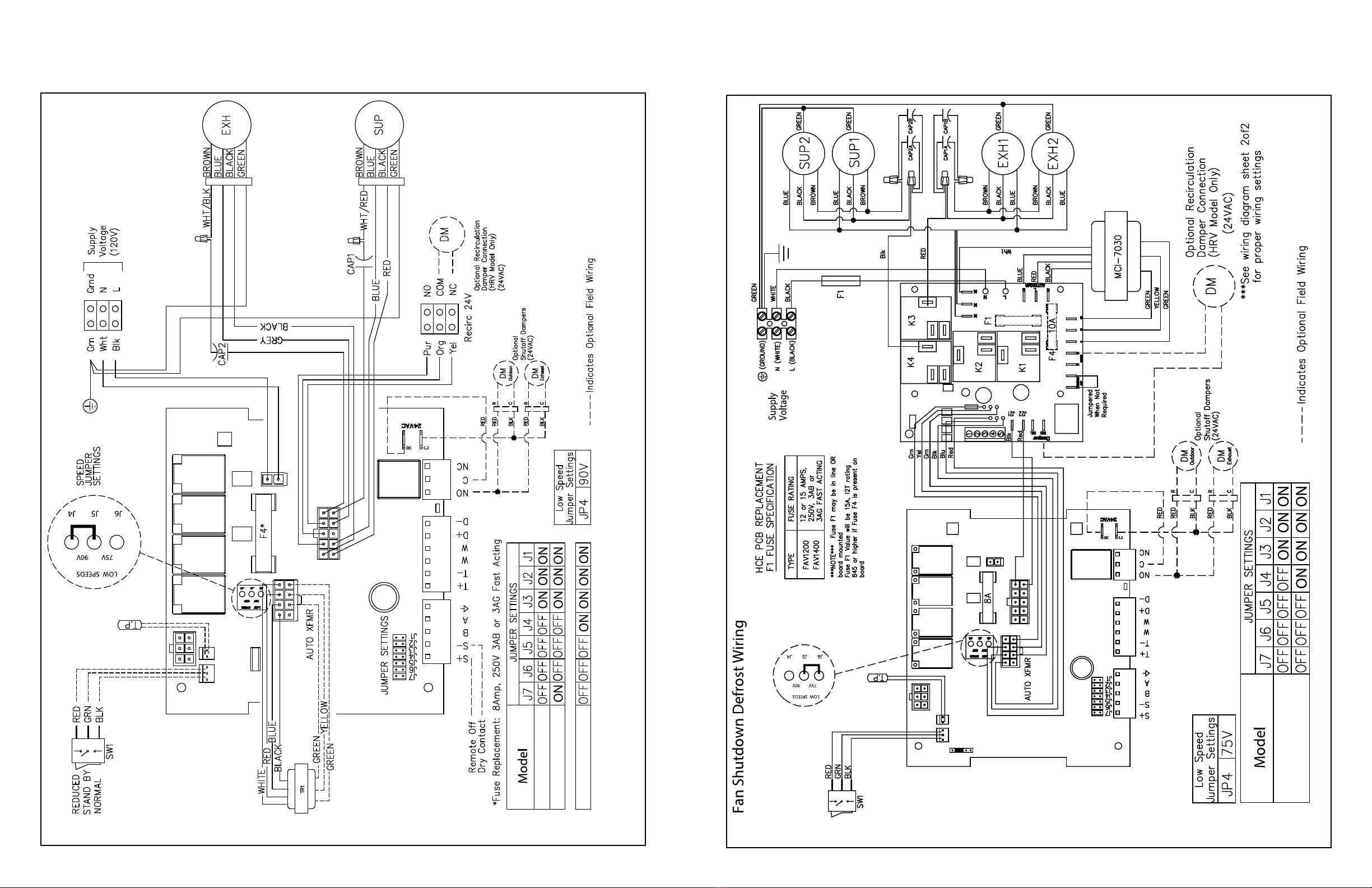
WIRING DIAGRAM (CONT'D)
WIRING DIAGRAM (CONT'D)
W
R
G
C
Y
WR G Y
Standard Furnace Interlock Wiring
THERMOSTAT
TERMINALS
FURNACE/HEATING
24-VOLT
TERMINAL BLOCK
FOUR
WIRE
TWO WIRE
heating only
TWO
WIRE
COOLING SYSTEM
W
R
G
C
Y
WR G Y
Alternate Furnace Interlock Wiring
THERMOSTAT
TERMINALS
FURNACE/HEATING
24-VOLT
TERMINAL BLOCK
FOUR
WIRE
TWO WIRE
heating only
TWO
WIRE
COOLING SYSTEM
WIRE JOINT
WIRING DIAGRAM TO
FORCED AIR SYSTEM
FOR A FURNACE
CONNECTION TO A COOLING
SYSTEM:
On some newer furnaces and older
thermostats, energizing the R and
G terminal at the furnace has the
effect of energizing the Y at the
thermostat and thereby turning on
the cooling system. If you identify this
type of thermostat, you must use the
“Alternate Accessory Control Contact.”
Standard Accessory Control Contact
Alternative Accessory Control Contact
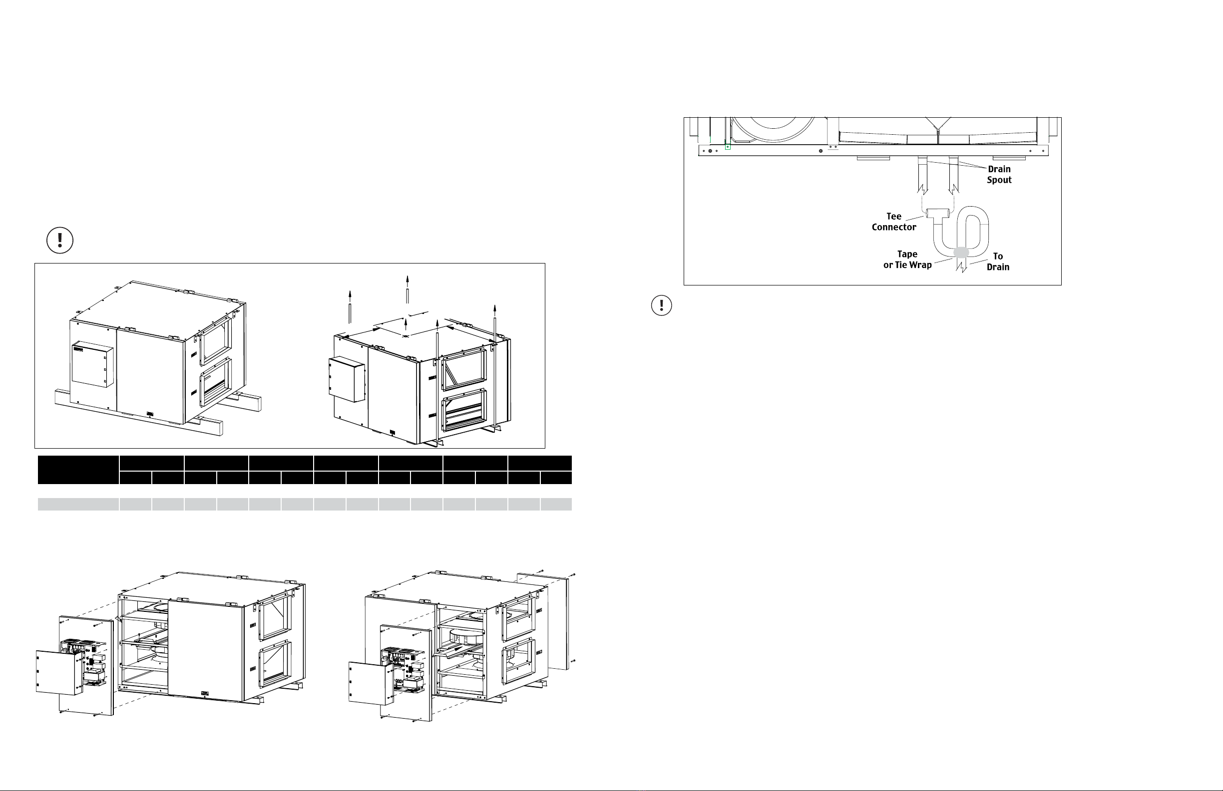
As per building codes and installation requirements for combustion appliances:
Air return ducts, or openings for air return, should not be placed in enclosed spaces containing combustion
appliances that are subject to spillage.
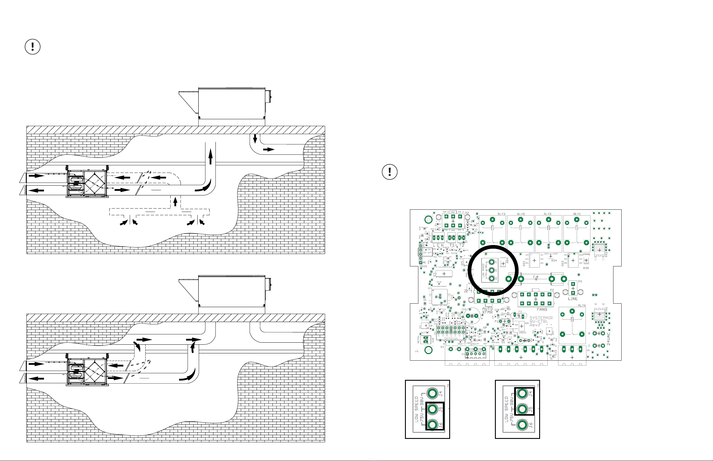
Installation Verification Test
LCH-4E, LCH-7E, LCH-12E Models
Without external control
1. Fan speed selector switch
• Set fan Speed selector switch to Standby.
2. Start-up
• Apply power to unit
• Unit should enter Exhaust only defrost mode for a 10 second duration and the following should occur:
Exhaust fan runs in HIGH (Normal) speed
Supply fan remains off
3. Standby
• Following the start-up unit should enter Standby mode. The following should occur:
Exhaust fan shuts off
Supply fan remains off
4. LOW (Reduced) speed
• Set fans speed selector switch LOW (Reduced) speed. The following should occur.
Exhaust fan runs in LOW (Reduced) speed
Supply fan runs in LOW (Reduced) speed
5. HIGH (Normal) speed
• Set fans speed selector switch HIGH (Normal) speed. The following should occur.
Exhaust fan ramps up to HIGH (Normal) speed
Supply fan ramps up to HIGH (Normal) speed
6. Test completion
• Set fan speed selector switch to desired setting
• Installation Verification test is complete
With external control
1. Start-up
• Apply power to unit
• Unit should enter Exhaust only defrost mode for a 10 second duration and the following should
occur:
Exhaust fan runs in HIGH (Normal) speed
Supply fan remains off
2.
• Following start-up unit will respond to external control
• Consult user manual/instruction provided with external controller and ensure unit responds
appropriately.
3. Test completion
• Installation Verification test is complete
Limited Warranty
• The energy recovery core has a
limited 3 year warranty.
• The warranty is limited to 3 years on
components and 3 years on motors
from the date of purchase, including
parts replaced during this time
period. If there is no proof of
purchase available, the date
associated with the serial number will
be used for the beginning of the
warranty period.
• The limited warranty covers normal
use. It does not apply to any
defects, malfunctions or failures as
a result of improper installation,
abuse, mishandling, misapplication,
fortuitous occurrence or any other
circumstances outside Greentek’s
control.
• Inappropriate installation or
maintenance may result in the
cancellation of the warranty.
• Any unauthorized work will result in
the cancellation of the warranty.
• Greentek is not responsible for any
incidental or consequential damages
incurred in the use of the ventilation
system.
• Greentek is not responsible for
providing an authorized service
centre near the purchaser or in the
general area.
• Greentek reserves the right to supply
refurbished parts as replacements.
• Transportation, removal and
installation fees are the responsibility
of the purchaser.
• The purchaser is responsible to
adhering to all codes in effect in his
area.
* This warranty is the exclusive and only warranty in
effect relative to the ventilation system and all other
warranties either expressed or implied are invalid.