Greentek LCH-4E User manual

INSTALLATION GUIDE
Greentek Models LCH-4E (Item No. 463303)
LCH-7E (Item No. 463304)
LCH-12E (Item No. 463305)
Product of Greentek
Greentek reserves the rights to modify a product, without prior notice,
whether in price, design, color or codes, in order to offer at all times quality products that are highly competitive.
Greentek
50 Kanalflakt Way, Bouctouche, NB E4S 3M5
Tel 1-888-724-5211 Fax 1-866-426-7430
www.Greentek.ca
Item# 444863 MARCH2019

2
IMPORTANT - PLEASE READ MANUAL BEFORE INSTALLATION
NOTICE: Prior to installing, serious consideration must be taken to insure this ventilation system will operate properly if integrated to any other type of
mechanical system, i.e. a forced air system, or an air handling unit. To insure proper operation & compatibilities of both system, it is required that the
airflow’s of the LCH Energy Recovery Ventilator (ERV) be balanced, by following the procedures found in this manual.
CAUTION: DO NOT INSTALL IN A COOKING AREA OR CONNECT DIRECTLY TO ANY APPLIANCES
CAUTION: TURN OFF ALL INTEGRAL DISCONNECTS BEFORE SERVICING
TO REDUCE OR AVOID THE HAZARDS OF ELECTRIC SHOCK AND FIRE: CAUTIONS CONCERNING THE OPERATION AND FULL EFFICIENCY OF THIS PRODUCT:
• While servicing of cleaning the ventilation system, always disconnect
from the main power.
• To reduce the chance or avoid the hazards of electric shock and fire, do
not perform any service to the ventilation system other than that stated
in the operating manual instructions.
• Do not use ventilation system for outdoor application.
• Do not pull or twist electrical connection when disconnecting it from
the ventilation system.
• Do not use the ventilation system for removal of flammable fumes or near
flammable gases.
• Use a dedicated power source.
• Do not obstruct or cover the air intake or air outlet of the ventilation
system.
• Do not modify, repair or disassemble this ventilation system. They are
to be performed by authorized serviced personnel only. Fire, electrical
shock and/or bodily injury may occur if not.
• To prevent injuries, do not operate the ventilation system while servicing
or maintaining. There are impeller wheels turning at a very high speed
that must fully stop rotating prior to accessing the inside of the unit.
• Always assess the operation of the ventilation system how it may
interact with vented combustion equipment (ie. Gas Furnace, Oil
Furnace, Combustion, Appliances, etc.)
LIMITED WARRANTY APPLICATIONS
All our products are backed by the best limited warranty in the industry,
for your peace of mind.
You benefit from a 3 year limited warranty on the polymer membrane core,
a 2-year limited warranty on our ventilation motors and a 2-year limited
warranty on all other components.
• Schools
• Locker Rooms
• Conference Rooms
• Restrooms
• Barber Shops
• Office Buildings
• Bars & Grills
• Classrooms
• Airports
• Floral Shops
• Veterinary Hospitals
• Stores
• Large Homes
• Restaurants

3
TABLE OF CONTENTS
1. Installation.................................................................................................................................................................................................................................................. 4
2. Optional Reversible Application ........................................................................................................................................................................................................... 4
3. Mounting or Hanging the ERV................................................................................................................................................................................................................. 5
4. Outside Fresh Air and Exhaust Air Hoods ........................................................................................................................................................................................... 6
5. Installation Ducts Warm Side to the ERV ............................................................................................................................................................................................ 6
6. Balancing the Unit with the Duotrol System ...................................................................................................................................................................................... 7
7. Types of Installations.............................................................................................................................................................................................................................8-9
8 . Operating of the Duotrol System......................................................................................................................................................................................................... 10
9 . Modes of Operations ............................................................................................................................................................................................................................. 11
10. Controls Connection............................................................................................................................................................................................................................. 12
11. Maintenance........................................................................................................................................................................................................................................... 13
12. Wiring Diagram LCH-4E....................................................................................................................................................................................................................... 14
13. Wiring Diagram LCH-7E ....................................................................................................................................................................................................................... 15
14. Wiring Diagram LCH-12E ..................................................................................................................................................................................................................... 16
15. Limited Warranty................................................................................................................................................................................................................................... 17
Greentek Product Numbers Explained
LCH-4E
L = Light
C = Commercial
H = Horizontal Configuration
4 = 450 CFM
H = Energy Recovery (ERV)
LCH-7E
L = Light
C = Commercial
H = Horizontal Configuration
4 = 750 CFM
H = Energy Recovery (ERV)
LCH-12E
L = Light
C = Commercial
H = Horizontal Configuration
4 = 1200 CFM
H = Energy Recovery (ERV)

4
LOCATION
The ERV must be located in a conditioned area where it will be possible to conveniently service the unit. The ERV would be located in the mechanical
room, above a drop ceiling or an area close to the outside wall where the weatherhoods will be mounted. Attic installations are not normally
recommended due to extreme temperatures variation, and difficulty in performing required service & maintenance. If an attic is selected, special care
should be taken in ensuring the unit will perform as intended. Unit may need to be protected with insulated shelter, built on site.
Connecting appliances to the ERV It is not recommended, including:
• clothes dryer
• kitchen exhaust hoods
• combustion venting
• central vacuum system
These appliances may cause lint, dust or grease to collect in the ERV, damaging the unit or risk of hazard.
Connecting any of these type of appliances to the ERV will void warranty
LCH-H series has dual has access doors on the front and back. Also, the main electrical control panel may be moved from front to back allowing for
ducting layout.
OUTDOOR AIR CONNECTIONS
(COLD SIDE)
OUTDOOR AIR CONNECTIONS
(COLD SIDE)
INDOOR AIR CONNECTIONS
(WARM SIDE)
INDOOR AIR CONNECTIONS
(WARM SIDE)
Default Configuration. Unit may be easily reversed in field.
1. INSTALLATION
2. OPTIONAL REVERSIBLE APPLICATION
LCH-4E, LCH-7E, LCH-12E

5
CONDENSATION DRAIN LINE
Through normal operation and including defrost sequence, the ERV may produce some condensation. The excess condensation should flow into a near-
by drain if no drain is available a condensation pump will be required. The ERV and all condensate lines must be installed in a conditioned space where
the temperature is maintained above the freezing point. A “P” trap is required in the drain line, This will prevent odors from being drawn back up into
the unit.
Drain Fitting
To Drain
(or to condensation pump)
Tape or Tie
Wrap
"T" Connector
Connecting the drain hose with recommended “P” trap
To insure a quiet operation, vibration isolators (not included) are recommended for both applications.
SADDLE
INSTALLATION
3. MOUNTING OR HANGING THE ERV
SUSPENDED
INSTALLATION

6
OUTSIDE WEATHER HOODS
The weatherhoods must have built-in screens to prevent birds and rodents from entering into the ductwork. The outside perimeter of the weatherhood must
be sealed to prevent leakage into the building. The design and size of the weatherhoods or louvers chosen by the installer must allow for adequate free area.
GOOD INSTALL PRACTICES
• Minimum distance not less than 10 ft. (3 m) apart from each other.
• Minimum 18 inches (457.2 mm) above snow line or ground level.
Outdoor intake air weather hood should be located to avoid contamination from sources such has:
• Exhaust Air openings
• Parking lots (auto exhaust)
• Combustion appliances
• Gas meters, oil fill pipes
• Garbage containers
• Attics or crawlspaces
• Under a deck or other areas of questionable air quality.
DUCTING TO AND FROM THE ERV
Galvanized sheet metal ducting with cross section, insuring all joints and seams are sealed with an approved commercial grade duct sealant of aluminum
foil tape. The outdoor air and the exhaust air duct from the weather hoods to the ERV must be fully insulated to minimize heat loss or heat gain and to avoid
potential condensation.Insulated flex duct may be used in moderation, if sized and installed properly. (Consult local or national safety & building codes.)
NOTE TO INSTALLER:
The ERV is a balanced ventilation system is designed to introduce outdoor air to the building while exhausting the same amount from the building. The
designer and installer must comply in accordance to local or national safety & building codes.
IMPORTANT: Insure the ERV runs in conjunction with the forced air system (Ref. wiring diagram for interlock connection)
To maximize airflow in the ductwork system, all ducts should be kept has straight as possible avoiding bends as possible. Insuring all joints and seams are
sealed with an approved commercial grade duct sealant of aluminum foil tape.
Tips:
Supply air ducting
In buildings without a forced air systems, fresh air is supplied to all main living areas. To maximize comfort the fresh air distribution ensure to install the
grilles or diffusers from a high wall or ceiling locations.
4. OUTSIDE FRESH AIR AND EXHAUST AIR HOODS
5. INSTALLATION DUCTS WARM SIDE TO THE ERV

7
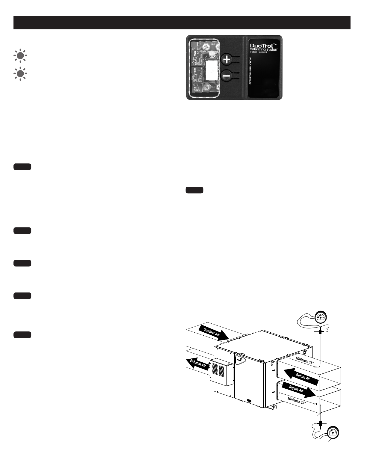
6. BALANCING THE UNIT WITH THE DUOTROL™ SYSTEM (LCH-4E & LCH-7E ONLY)
The light indicator shows you in which mode the
DuotrolTM System is in.
GREEN LIGHT Mode Selector
YELLOW LIGHT Balancing Mode
USING THE SELECTOR SWITCH
NOTE TO INSTALLER
When on Balancing Mode, the Selector Switch
allows you to choose the motor you want to set.
Closed Duotrol Cover
1. INTER (Exhaust Motor)
2. CONT (Both Motors)
3. OFF (Supply Motor)
Step 1 Press the (+) and (–) buttons on the Duotrol™ simultaneously
until you see the yellow light. Once the indicator light turns
yellow and the unit goes to high speed you are in balancing mode.
When in balancing mode the selector switch on the Duotrol™
becomes the motor selector switch:
INTER = Exhaust Airflow Motor
CONT = Both Motors
OFF = Supply Airflow Motor
Step 2 To adjust the (fresh air), select the «OFF» position on the
Duotrol™. To adjust the airflow rates, press the (–) button to
decrease or press the (+) button to increase the airflow rates
until you reach the calculated fresh airflow requirements.
Step 3 To adjust the (stale air) select the «INTER» position on the
Duotrol™. To adjust the airflow rates, press the (–) button to
decrease or press the (+) button to increase the airflow rates
until you reach the calculated stale airflow requirements.
Step 4 Once this is completed and you have balanced the airflow rates
required for your application. Proceed to exit the balancing
mode you must press (+) and (–) buttons on the Duotrol™
simultaneously until solid green LED appears then release. The
indicator light will turn green to indicate normal operation mode.
Step 5 Mark down the balanced air flow rates information. Apply the
label to the ERV access door for future reference (e.g. date,
balance airflow rate, your name, phone number and business
address).
Step 6 Once the ERV is balanced, switch to «CONT» on the Duotrol™
By using (+) and (–) buttons you can set the continuous speed if
required.
Note : When selecting the CONT mode: The ERV will continuously exhaust
stale indoor air to the outside and will introduce fresh outdoor
air continuously on low speed except when there is a request for
ventilation by one of the remote controllers then the ventilation system
will exchange at high speed. (Recommended for maximum indoor air
quality.)
When selecting the INTER mode: The only ERV will only run on high
speed when there is a request for ventilation. At this time the unit will
run on high speed until the level of humidity is below the set point. The
T-3 timer has completed its time period or once the cycles per hour has
completed its cycle.
DuotrolTM System
NOTICE: To balance the LCH-12E it will require balancing damper in the ductwork since the Duotrol does not offer this balancing feature at the current moment.
Pitot tube
Magnahelic gauge
Pitot tube
Magnahelic gauge
Note: Insert pitot
tube minimum 18”
from unit, blower or
elbows. The same
applies when using
air flow stations.

8
* Illustration & example, port locations and airflow directions may vary, consult unit specification sheet and drawings.
It is important the duct design is sized accordingly to the application to insure the system related to the ERVs airflow and performance specifications. The
amount of air (CFM) that an ERV will deliver is directly related to the total external static pressure (E.S.P.) of the system. Static pressure is a measure of
resistance imposed on the blower by length of duct work/number of fittings used in duct work, duct heater etc.
DIRECT DUCTED SYSTEM APPLICATION
• Exhausting of stale air accumulated in the building.
• Supply air supplied to main living areas.
• ERV airflow must be balanced according to the building’s airflow requirements.
• Optional : External heating or cooling coil may be to insure maximum comfort.
ERV
SUPPLY AIR DUCT
RETURN AIR
RETURN AIR TO ERV
AIR HANDLER
SUPPLY AIR
BALANCING DAMPERS - LCH-12E ONLY
OUTDOOR AIR
EXHAUST AIR
OUTDOOR AIR
EXHAUST AIR
ERV
SUPPLY AIR
RETURN AIR SUPPLY AIR
BALANCING DAMPERS - LCH-12E ONLY
EXTENDED EXHAUST SYSTEM APPLICATION
• Exhausting of stale air accumulated in the building.
• Supply air supplied to the return air duct of the air handler.
• Insure the ERV runs in conjunction with air handler unit.
• ERV airflow must be balanced according to the building’s airflow requirements.
7. TYPES OF INSTALLATIONS

9
* Illustration & example, port locations and airflow directions may vary, consult unit specification sheet and drawings.
ERV
RETURN AIR DUCT
AIR HANDLER
SUPPLY AIR
BALANCING DAMPERS -
LCH-12E ONLY
OUTDOOR AIR
EXHAUST AIR
SUPPLY AIR DUCT
SIMPLIFIED SYSTEM INSTALLATION
• Exhausting of stale air accumulated in the building from
the return air duct of the air handler.
• Supply air supplied to the return air duct of the air
handler unit down stream of the exhaust air.
• Insure the ERV runs in conjunction with air handler unit
• ERV airflow must be balanced according to the
building’s airflow requirements
7. TYPES OF INSTALLATIONS (CONT..)

10
8. OPERATING OF THE DUOTROL™ SYSTEM
Our Duotrol
TM
System is state of
the art technology simplified for
quick and easy operation. The
Duotrol™ System serves two
purposes:
1. ACTS AS A MODE SELECTOR IN RUN MODE
(OFF, CONT & INTER)
• OFF: When the selector switch is in the OFF position the ventilation
system will not come on even if there’s a request for ventilation from
any remote controllers.
• CONT: When the selector switch is in the CONT position the
ventilation system will exhaust stale indoor air to the outside and will
introduce fresh outdoor air continuously on low speed except when
there is a request for ventilation by one of the remote controllers then
the ventilation system will exchange at high speed. (Recommended
for maximum indoor air quality.)
• INTER: When the selector switch is in the INTER position the
ventilation system will only run on high speed when there is a request
for ventilation. At this time the unit will run on high speed until the
level of humidity is below the set point. The T-3 timer has completed
its time period or once the cycles per hour has completed its cycle.
TIP:
During hot and humid days, it is recommended that you put the
system on INTERM mode. This will reduce the amount of warm and
humid fresh air coming inside the dwelling.
NOTE:
The following controls (EHC1.0, EHC1.5, RD-2, RD-3P, RD-4P)
will override any setting on the Duotrol
TM
all except when in the OFF
position.
2. ACTS AS VARIABLE SPEED SELECTOR
(LCH-4E & LCH-7E only)
•
When the (+) button is pushed this will increase the CONT speed of
both ventilation system motors from the previous settings.
•
When the (-) button is pushed this will decrease the CONT speed of
both ventilation system motors from the previous settings.
NOTE:
When the LED stops blinking the unit is at its maximum high
speed or at its maximum low speed.
IMPORTANT:
If speed setting is too high, extreme dryness can occur
in home during winter months. If speed setting is too high, extreme
humidity levels can occur during hot humid days.
IMPORTANT:
If speed setting is too low, above normal humidity, stale
and contaminated air levels can occur in dwelling.

11
1. Continous
When the selector switch is in the CONT position the ventilation system will exhaust
stale indoor air to the outside and will introduce fresh outdoor air continuously on low
speed except when there is a request for ventilation by one of the remote controllers
then the ventilation system will exchange at high speed. (Recommended for maximum
indoor air quality.)
9. MODES OF OPERATIONS
Fresh air to
dwelling
Stale air to
outside
Fresh air from
outside
Stale air from
dwelling
Stale air to
outside
Stale air from
dwelling
Normal
Evacuation
DEFROST CYCLE TYPES:
Defrost sequence type: Evacuation (Ref. Supply fan shut down)
An automatic defrost sequence is activated at an outdoor measured temperature of
-5°C (23°F) and colder.
During the electronically controlled defrost sequence, the supply motor (incoming air)
shuts down while the exhaust motor continues to run to exhaust distribute warm
ambient air through the core. This eliminates the risk of the ERV core from building up
with ice and freezes.

12
CAUTION:
Minimum wire requirements is LVT18 CSA/UL 4 strain to insure proper connection.
RD-2, RD-3P, RD-4P (4 WIRES)
Installation of a RD-Series main wall control with your ERV will improve comfort and may significantly reduce the product’s energy use.
VECTRA SERIES - MODEL EHC 1.0 & EHC 1.5 (4 WIRES)
Installation of a Vectra Series main wall control with your ERV will improve comfort and may significantly reduce the product’s energy use.
To Casing
Screw
for Ground
Jumper
JP-4*
2 Relays
LVC Version 1
B
INTERLOCK
COMN.O.N.C.
RLY1
4321
D1
SW3
TIMER
REMOTE
W
B1 GR
GBR
MASTER
PROG
J2
–
+
B
INTERLOCK
COMN.O.N.C.
RLY1
4321
D1
SW3
TIMER
REMOTE
W
B1 GR
GBR
MASTER
PROG
J2
–
+
B
INTERLOCK
COMN.O.N.C.
RLY1
4321
D1
SW3
TIMER
REMOTE
W
B1 GR
GBR
MASTER
PROG
J2
–
+
R
G
R
G
R
G
B
W
R
G
B
W
BGRBGR
B
INTERLOCK
COMN.O.N.C.
RLY1
4321
D1
SW3
TIMER
REMOTE
W
B1 GR
GBR
MASTER
PROG
J2
–
+
RLY2BGWR
Jumper
JP-4*
1 Relay
LVC Version 1
B
INTERLOCK
COMN.O.N.C.
RLY1
4321
D1
SW3
TIMER
REMOTE
W
B1 GR
GBR
MASTER
PROG
J2
–
+
BGWR
B
INTERLOCK
COMN.O.N.C.
RLY1
4321
D1
SW3
TIMER
REMOTE
W
R
B1
G
W
B1 GR
GBR
MASTER
PROG
J2
–
+
R
B1
G
W
COMNCNOB G
INTERLOCK TIMER / MINUTERIE
RB/B1 WG
CONTROL / COMMANDE
R
COMNCNOB G
INTERLOCK TIMER / MINUTERIE
RB/B1 WG
CONTROL / COMMANDE
R
COMNCNOB G
INTERLOCK TIMER / MINUTERIE
RB/B1 WG
CONTROL / COMMANDE
R
COMNCNOB G
INTERLOCK TIMER / MINUTERIE
RB/B1 WG
CONTROL / COMMANDE
R
Terminal Barrier ERV/ERV Connection
Low Voltage
ERV
Controller
Low Voltage
ERV
Controller
Low Voltage
ERV
Controller
Low Voltage
ERV
Controller
Terminal Barrier ERV/ERV Connection
RD-1 (2 WIRES)
Installation of a RD-1 main wall control with your ERV will improve comfort and may significantly reduce the product’s energy use.
To Casing
Screw
for Ground
Jumper
JP-4*
2 Relays
LVC Version 1
B
INTERLOCK
COMN.O.N.C.
RLY1
4321
D1
SW3
TIMER
REMOTE
W
B1 GR
GBR
MASTER
PROG
J2
–
+
B
INTERLOCK
COMN.O.N.C.
RLY1
4321
D1
SW3
TIMER
REMOTE
W
B1 GR
GBR
MASTER
PROG
J2
–
+
B
INTERLOCK
COMN.O.N.C.
RLY1
4321
D1
SW3
TIMER
REMOTE
W
B1 GR
GBR
MASTER
PROG
J2
–
+
R
G
R
G
R
G
B
W
R
G
B
W
BGRBGR
B
INTERLOCK
COMN.O.N.C.
RLY1
4321
D1
SW3
TIMER
REMOTE
W
B1 GR
GBR
MASTER
PROG
J2
–
+
RLY2BGWR
Jumper
JP-4*
1 Relay
LVC Version 1
B
INTERLOCK
COMN.O.N.C.
RLY1
4321
D1
SW3
TIMER
REMOTE
W
B1 GR
GBR
MASTER
PROG
J2
–
+
BGWR
B
INTERLOCK
COMN.O.N.C.
RLY1
4321
D1
SW3
TIMER
REMOTE
W
R
B1
G
W
B1 GR
GBR
MASTER
PROG
J2
–
+
R
B1
G
W
COMNCNOB G
INTERLOCK TIMER / MINUTERIE
RB/B1 WG
CONTROL / COMMANDE
R
COMNCNOB G
INTERLOCK TIMER / MINUTERIE
RB/B1 WG
CONTROL / COMMANDE
R
COMNCNOB G
INTERLOCK TIMER / MINUTERIE
RB/B1 WG
CONTROL / COMMANDE
R
COMNCNOB G
INTERLOCK TIMER / MINUTERIE
RB/B1 WG
CONTROL / COMMANDE
R
Terminal Barrier ERV/ERV Connection
Low Voltage
ERV
Controller
Low Voltage
ERV
Controller
Low Voltage
ERV
Controller
Low Voltage
ERV
Controller
Terminal Barrier ERV/ERV Connection
T3 TIMER (3 WIRES)
To Casing
Screw
for Ground
Jumper
JP-4*
2 Relays
LVC Version 1
B
INTERLOCK
COMN.O.N.C.
RLY1
4321
D1
SW3
TIMER
REMOTE
W
B1 GR
GBR
MASTER
PROG
J2
–
+
B
INTERLOCK
COMN.O.N.C.
RLY1
4321
D1
SW3
TIMER
REMOTE
W
B1 GR
GBR
MASTER
PROG
J2
–
+
B
INTERLOCK
COMN.O.N.C.
RLY1
4321
D1
SW3
TIMER
REMOTE
W
B1 GR
GBR
MASTER
PROG
J2
–
+
R
G
R
G
R
G
B
W
R
G
B
W
BGRBGR
B
INTERLOCK
COMN.O.N.C.
RLY1
4321
D1
SW3
TIMER
REMOTE
W
B1 GR
GBR
MASTER
PROG
J2
–
+
RLY2BGWR
Jumper
JP-4*
1 Relay
LVC Version 1
B
INTERLOCK
COMN.O.N.C.
RLY1
4321
D1
SW3
TIMER
REMOTE
W
B1 GR
GBR
MASTER
PROG
J2
–
+
BGWR
B
INTERLOCK
COMN.O.N.C.
RLY1
4321
D1
SW3
TIMER
REMOTE
W
R
B1
G
W
B1 GR
GBR
MASTER
PROG
J2
–
+
R
B1
G
W
COMNCNOB G
INTERLOCK TIMER / MINUTERIE
RB/B1 WG
CONTROL / COMMANDE
R
COMNCNOB G
INTERLOCK TIMER / MINUTERIE
RB/B1 WG
CONTROL / COMMANDE
R
COMNCNOB G
INTERLOCK TIMER / MINUTERIE
RB/B1 WG
CONTROL / COMMANDE
R
COMNCNOB G
INTERLOCK TIMER / MINUTERIE
RB/B1 WG
CONTROL / COMMANDE
R
Terminal Barrier ERV/ERV Connection
Low Voltage
ERV
Controller
Low Voltage
ERV
Controller
Low Voltage
ERV
Controller
Low Voltage
ERV
Controller
Terminal Barrier ERV/ERV Connection
10. CONTROLS CONNECTION

13
WARNING BE SURE TO DISCONNECT THE ELECTRICAL POWER BEFORE SERVICING THE SYSTEM.
ROUTINE MAINTENANCE REQUIRED
SEVEN-STEP SCHEDULE
With routine prevention maintenance, you can avoid unnecessary
problems and ensure the effectiveness of your ERV and prolong its life. For
specific routine maintenance please contact your local HVAC contractor.
1. Clean or replace air filters. Filters, which are located within the ERV
should be cleaned every two to three months. Filters should be vacuumed
first, then washed with a mild soap and water. Most washable filters will last
several years before needing to be replaced.
2. Clean the exterior intake and exhaust vents of obstructions.Check the
outside vents regularly to ensure that the screen openings are not
obstructed by grass, bushes, leaves, snow or other debris.
3. Clean and inspect the energy recovery core twice a year and clean it as
required (consult your owner’s manual for instructions on inspecting and
cleaning the core). A build-up of dust and dirt can restrict airflow and reduce
the efficiency of your ERV. After inspection and cleaning, make sure the core
is replaced right-side-up.
4. Clean the condensate drain and pan. Twice a year, check the condensate drain and tubing to ensure that they are open and free-flowing. The tubing can
be disconnected for cleaning. The condensate drain must have a “trap” in the tubing that traps a quantity of water – to prevent air from entering the ERV via
this tubing.
5. Service the fans. The fans on the ERV’s are designed to operate continuously without lubrication. Inspect the blower fans periodically for dirt on the blades,
and remove it by gently brushing the blades or using a vacuum cleaner.
6. Clean the grilles and inspect the ductwork. Clean the grilles when they are dusty. At least once a year, visually inspect the ductwork leading to and from
the ERV. Damaged ducts can lead to condensation problems, including wet insulation, water on the floor and, ice build-up. If the insulation itself is damaged.
7. Arrange for an annual servicing. Your ERV should undergo annual general servicing by a certified contractor and who is familiar with your ERV. If possible,
have your furnace and ERV serviced at the same time; this will result in less inconvenience and cost than two separate visits.
11. MAINTENANCE
ALUMINUM CROSS-FLOW ERV CORE

14
LOW SPEEDS
90V75V
J4J5J6
12. WIRING DIAGRAM LCH-4E

15
LOW SPEEDS
90V75V
J4J5J6
13.WIRING DIAGRAM LCH-7E

16
LOW SPEEDS
90V75V
J4J5J6
14. WIRING DIAGRAM LCH-12E

17
2-YEAR LIMITED WARRANTY ON COMPONENTS - Greentek warrants the components (controls, sensor & electronics) to be free from defects in
material and workmanship. If a defect is found within the models warranty period from date of original installation of the product (whether or not
actual use begins on that date). Greentek will provide a new or re-manufactured part, at its’ discretion, to authorize replacement of defective
part,without charge for the part itself.
2-YEAR LIMITED WARRANTY ON VENTILATION MOTORS – Greentek warrants the ventilation motors against defects in material and
workmanship within the models warranty period from the date of original installation. Greentek will provide a new or re-manufactured part, at its’
discretion, to authorize replacement of defective part, without charge for the part itself.
3-YEAR LIMITED WARRANTY ON POLYMER MEMBRANE ENERGY RECOVERY CORE – Greentek warrants the polymer energy recovery core against
defects in material and workmanship for a lifetime from the date of original installation. Greentek will provide a new or re-manufactured part, at its’
discretion, to authorize replacement of defective part, without charge for the part itself.
1-YEAR LIMITED WARRANTY – Greentek warrants replacement parts that have been replaced after the standard period of the previous limited
warranty, to be free from defects in material and workmanship. If a defect is found within one year from date of original installation of replacement
part, (whether or not actual use begins on that date) Greentek will provide a new or re-manufactured part, at its’ discretion, to authorize
replacement of defective part, without charge for the part itself.
WARRANTY CONDITIONS – Warranties apply only to Greentek products installed in their original location. Installation, use, care, and maintenance
must be normal and in accordance with instructions contained in the Owner’s Manual and service information. Defective parts must be returned to
the distributor through a registered servicing dealer for credit. All work shall be performed by a certified technician.
GREENTEK WILL NOT BE RESPONSIBLE FOR – Normal maintenance, installation, including filter cleaning and/or replacement, damage or repairs
required as a consequence of faulty installation, misapplication, abuse, improper servicing,unauthorized alteration or improper operation. Damage
as a result of floods, winds, fires, lightning, accidents, corrosive environments or other conditions beyond the control of Greentek. Parts not supplied
or designated by Greentek, or damages resulting from their use.
NOTICE: None of these warranties include labor or other costs incurred for diagnosing, repairing, removing, installing, shipping, servicing or
handling of either defective parts, or replacement parts, or new units.
15. LIMITED WARRANTY

50 Kanalflakt Way., Bouctouche, NB E4S 3M5
1-888-724-5211 Fax 1-866-426-7430
www.greentek.ca
Item#444863

Modèle Greentek LCH-4E (No. pièce 463303)
LCH-7E (No. pièce 463304)
LCH-12E (No. pièce 463305)
Item# 444863 MARCH2019
MANUEL D’INSTALLATION
Produit de Greentek
Greentek se réserve le droit de modifier un produit, sans pré-avis, soit en prix,
conception, couleur ou code pour offrir en tout temps des produits compétitifs de qualité supérieure.
Greentek
50 Kanalflakt Way., Bouctouche, NB E4S 3M5
1-888-724-5211 Fax 1-866-426-7430
www.greentek.ca

20
IMPORTANT – LISEZ LE MANUEL AVANT DE PROCÉDER À L’INSTALLATION
AVERTISSEMENT: Avant de procéder à l’installation, prenez bien soin de vérifier que cet appareil de ventilation pourra fonctionner convenablement s’il
est intégré à tout autre type de système mécanique, comme un système à air pulsé ou une centrale d’air. Pour que l’appareil fonctionne convenablement et
soit compatible avec tout système existant, le débit du ventilateur récupérateur de chaleur (VRE) LCH doit être équilibré selon la procédure décrite dans le
présent manuel.
MISE EN GARDE: NE PAS INSTALLER DANS UNE AIRE DE CUISSON NI BRANCHER DIRECTEMENT À UN AUTRE APPAREIL
MISE EN GARDE : COUPEZ TOUTE ALIMENTATION ÉLECTRIQUE À LA SOURCE AVANT DE PROCÉDER À L’INSTALLATION
OU À L’ENTRETIEN DE L’APPAREIL
POUR RÉDUIRE OU ÉLIMINER LES RISQUES D’ÉLECTROCUTION ET D’INCENDIE MISES EN GARDE CONCERNANT LE FONCTIONNEMENT ET L’EFFICACITÉ DE CE PRODUIT
• Déconnectez toujours l’alimentation électrique principale avant de procéder
au nettoyage ou à l’entretien de l’appareil.
• Pour réduire les risques d’électrocution et d’incendie, n’effectuez aucune
tâche d’entretien du système de ventilation qui n’est pas décrite dans
lesinstructions du manuel d’utilisation.
• N’installez pas le système de ventilation à l’extérieur.
• Évitez de tirer ou de tordre les connecteurs électriques en les débranchant
du système de ventilation.
• N’utilisez pas le système de ventilation pour évacuer des vapeurs
inflammables et ne l’installez pas à proximité de sources de
gazinflammables.
• L’appareil doit avoir une source d’alimentation dédiée.
• Évitez d’obstruer ou de couvrir les bouches d’admission ou d’évacuation
dusystème de ventilation.
• Évitez de modifier, réparer ou démonter ce système de ventilation. Ces tâches
doivent être accomplies par le personnel d’entretien autorisé. Toute violation
de cette directive entraîne des risques d’électrocution et de blessure.
• Pour prévenir les blessures, évitez de faire fonctionner le système de
ventilation pendant une réparation ou l’entretien. L’appareil contient
des roues centrifuges tournant à très grande vitesse; il est important
d’attendre leur arrêt complet avant d’accéder à l’intérieur de l’appareil.
• Vérifiez toujours comment le fonctionnement du système de ventilation
se comportera avec les appareils de combustion à évacuation des gaz
(chaudière au gaz et au mazout, appareils à combustion, etc.)
GARANTIE LIMITÉE APPLICATIONS
Tous nos produits sont couverts par la meilleure garantie limitée de l’industrie,
pour votre tranquillité d’esprit.
Une garantie limitée de 15 ans couvre le noyau en aluminium, une
garantie limitée de 2 ans couvre les moteurs de ventilation et tous les
autrescomposants.
• Écoles
• Vestiaires
• Salles de conférence
• Toilettes
• Salons de coiffure
• Immeubles de bureaux
• Bars et grillades
• Salles de classe
• Aéroports
• Fleuristes
• Hôpitaux vétérinaires
• Magasins
• Grandes maisons
• Restaurants
Other manuals for LCH-4E
1
This manual suits for next models
2
Table of contents
Languages:
Other Greentek Fan manuals
Popular Fan manuals by other brands

QuietCool
QuietCool CL-1500 owner's guide

emerio
emerio TFN-212915.10 instruction manual

Monte Carlo Fan Company
Monte Carlo Fan Company 5DI52 Series owner's manual

Casablanca
Casablanca 59090 Owner's guide and installation manual

Atlas fan company
Atlas fan company Acqua instruction manual

Noctua
Noctua NF-P12 user manual