Greentek RNC12 HRV User manual

INSTALLATION GUIDE
RESIDENTIAL USE ONLY
Item# 463613 OCT2018
Greentek Models
RNC12 HRV (Item No. 463118)
RNC 1.0 HRV (Item No. 463054)
RNC 1.5 HRV (Item No. 463051)
RNC 2.0 HRV (Item No. 463125)
RNC 2.0ES HRV (Item No. 463117)
Product of Greentek
Greentek reserves the rights to modify a product, without prior notice,
whether in price, design, color or codes, in order to offer at all times quality products that are highly competitive.
Greentek
50 Kanalflakt Way, Bouctouche, NB E4S 3M5
1-888-724-5211 Fax 1-866-426-7430
www.Greentek.ca

Page 2
IMPORTANT - PLEASE READ MANUAL BEFORE INSTALLATION
CONTENTS
TO REDUCE OR AVOID THE HAZARDS OF ELECTRIC SHOCK AND FIRE:
CAUTIONS CONCERNING THE OPERATION AND FULL EFFICIENCY OF THIS PRODUCT:
CAUTION: Do not install in a cooking area or connect directly to any appliance. Turn off all integral disconnects before servicing.
NOTICE:
Prior to installing, serious consideration must be taken to insure this ventilation system will operate properly if integrated to any other type of
mechanical system, i.e. a forced air system, or an air handling unit. To insure proper operation & compatibilities of both system, it is required that the airflow’s of
the Heat Recovery Ventilator (HRV) or Energy Recovery Ventilator (ERV) be balanced, by following the procedures found in this manual.
The way that your Heat/Energy-recovery ventilator is installed may make a significant difference to the electrical energy that you will use. To minimize the
electricity use of the Heat/Energy-recovery ventilator, a stand-alone fully ducted installation is recommended. If you choose a simplified installation that operates
your furnace airhandler for room-to-room ventilation, an electrically efficient furnace that has an electronically commutated (EC) variable speed blower motor will
minimize your electrical energy consumption and operating cost.
LIMITATIONS: The product is for residential applications only. Must be installed in accordance with all national and local regulations, building and safety codes.
SECTION PAGE
1. Ventilation requirements . . . . . . . . . . . . . . . . . . . . . . . . . 3
2. Fitting equivalent lengths. . . . . . . . . . . . . . . . . . . . . . . . . 4
3. Types of Installations . . . . . . . . . . . . . . . . . . . . . . . . . . . 5
4. Installation of the HRV / ERV . . . . . . . . . . . . . . . . . . . . . . . 7
5. Insulated Flex from Unit to Outside Wall . . . . . . . . . . . . . . . . . 7
6. Condensation Drain Line . . . . . . . . . . . . . . . . . . . . . . . . . 8
7. Dedicated Electric Receptacle . . . . . . . . . . . . . . . . . . . . . . 8
8. Outside Fresh Air and Stale Air Hoods . . . . . . . . . . . . . . . . . . 8
9. The matrix™ High Performance Ventilation Hood . . . . . . . . . . . . 9
10. Benefits of the Duotrol™ System . . . . . . . . . . . . . . . . . . . . 9
11. Balancing the unit . . . . . . . . . . . . . . . . . . . . . . . . . . . .10
12. Controls Connection. . . . . . . . . . . . . . . . . . . . . . . . . . .12
13. Wiring Diagrams for furnace interlock systems . . . . . . . . . . . . .13
14. Troubleshooting . . . . . . . . . . . . . . . . . . . . . . . . . . . . .14
15. Maintenance . . . . . . . . . . . . . . . . . . . . . . . . . . . . . .15
16. Balancing Charts . . . . . . . . . . . . . . . . . . . . . . . . . . . .16
• Before servicing or cleaning the HRV system, always remove the power cord
from the AC wall outlet.
• To reduce the hazards of electric shock or fire, do not perform any service
to the HRV system other than those stated in the operating manual
instructions.
• To reduce the risk of electric shock, this ventilation system (HRV/ERV)
comes equipped with a 3-prong plug-in. This plug will fit in a polarized outlet
only one way.
• Do not use ventilation system for outdoor application.
• Do not pull or twist power cord when disconnecting it from the ventilation
system. Grasp the plug firmly, not the cord.
• Do not modify the power plug in any way; if modified, risk of electric shock
fire or even damage to the unit may occur.
• Do not use the ventilation system for removal of flammable fumes, gases or
connect directly to any appliances.
• Use a dedicated AC 120V outlet only.
• Do not obstruct or cover the air intake or air outlet of the ventilation system.
• Do not modify, repair or disassemble this system. These tasks are to be
performed by authorized serviced personnel only. Fire, electrical shock and/
or bodily injury may occur if these warnings are not followed.
• To prevent injuries, do not operate the ventilation system, while servicing
or maintaining. There are impeller wheels turning at a very high speed that
must fully stop rotating prior to accessing the inside of the unit.
• Always assess the operation of the ventilation system on how it may
interact with vented combustion equipment (ie. Gas Furnace, Oil Furnace,
Combustion, Appliances, etc.)
• Do not use for swimming pool/spa applications.

Page 3
1. VENTILATION REQUIREMENTS
DETERMINE YOUR
VENTILATION NEEDS
INSTALLATION
How much fresh air do I need? Good air
quality is based in part on the capacity
of the home’s ventilation system.
Usually, the HRV’s/ERV’s capacity
is measured in CFM (Cubic Feet per
Minutes) or L/s (Liters per Seconds) of
fresh air being distributed in the living
space. The Room Count Calculation or
the Air Change per Hour Method shows
you how to determine your ventilation
needs. (see chart on right)
A. Room Count Calculation
LIVING SPACE NUMBER OF ROOMS CFM (L/S) CFM REQUIRED
Master Bedroom ———— x 20 cfm (10 L/s) = ————
With Basement ———— x 20 cfm (10 L/s) = ————
Single Bedroom ———— x 10 cfm (5 L/s) = ————
Living Room ———— x 10 cfm (5 L/s) = ————
Dinning Room ———— x 10 cfm (5 L/s) = ————
Family Room ———— x 10 cfm (5 L/s) = ————
Recreation Room ———— x 10 cfm (5 L/s) = ————
Other ———— x 10 cfm (5 L/s) = ————
Kitchen ———— x 10 cfm (5 L/s) = ————
Bathroom ———— x 10 cfm (5 L/s) = ————
Laundry Room ———— x 10 cfm (5 L/s) = ————
Utility Room ———— x 10 cfm (5 L/s) = ————
TOTAL ventilation requirement (add last column) = ————
1 CFM = 0.47189 L/s
1 L/s = 3.6 m3/hr
B. Air Change per Hour Method
TOTAL cu ft X 0.35 per hr = total
Take total and divide by 60 to get CFM
Example: A 25’x 40’ house with basement
1,000 Sq. ft. x 8’ high x 2(1st floor + basement) = 16,000 cu. ft.
16,000 cu. ft. x 0.35 ACH = 5,600 cu. ft.
5,600 cu. ft. / 60 Minutes = 93.3 CFM
93.3 CFM is your ventilation need

Page 4
2. FITTING EQUIVALENT LENGTHS
- Flex pipe equivalent length is smooth
pipe x2
- Flex fitting equivalent length is
smooth fitting x2
- 45º perimeter pipe elbow equivalent
length = 5 ft. (1.52 m)
NOTE: Where flex duct is used
to make 45º elbow
equivalent length =
10 ft. (3.0 m)
- Y-equal sides
equivalent length = 10 ft. (3.0 m)
- Y-Side branch
equivalent length =
35 ft. (10.7 m)
- Round plastic diffuser
equivalent length = 100 ft. (30.5 m)
NOTE: Maximum airflow assumes
diffuser is in full open position.
- Tee take-off
equivalent length =
50 ft. (15.24 m)
- Angle boot
equivalent length = 30 ft. (9.14 m)
- 90º perimeter pipe elbow equivalent
length = 10 ft. (3.0 m)
NOTE: Where flex duct is used
to make 90º elbow
equivalent length = 20 ft. (6.1 m)
- Round wall cap spring
damper or screen
equivalent lengths =
60 ft. (18.29 m)
- Wall grill 50% free area
equivalent length = 15 ft. (4.6 m)
- Increaser/Reducer
equivalent length
= 8 ft. (2.43 m)

Page 5
3. TYPES OF INSTALLATIONS
DIRECT DUCTED SYSTEM
This application uses a devoted
duct system for the supply
and the exhausting of stale air
accumulated in the home.
It is recommended to install fresh
air grilles in all bedrooms and living
areas. Exhaust the stale air from
the bathroom, kitchen and laundry
room. (see figure 3.1)
IMPORTANT:
For optimal
performance of your HRV or ERV, the
installation of an optional 6” round
galvanized backdraft damper is
required on the fresh air to home duct
work.
figure 3.1
EXTENDED EXHAUST
SYSTEM
This application uses a devoted
duct system for the exhausting of
stale air accumulated in the home.
The fresh air is dumped into the
return air duct and is distributed
thru the home by the existing
supply air ductwork of the forced
air system. (see figure 3.2)
Make sure when using this application
that your fresh air duct connection to
the forced air system return air duct
is not less than 10ft (3 m) upstream of
the return plenum connection to the
forced air system. Check with your
local code or the forced air system’s
manufacturer. The HRV and forced air
system must be in continuous mode,
to achieve maximum comfort and to
avoid cross-contamination.
NOTE TO INSTALLER: Dwellings
with multiple forced air systems
requires one HRV/ERV per system.
Insure the unit runs in conjunction
with forced air system (Ref. wiring
diagram for furnace interlock)
figure 3.2
* For minimum distance between
return and forced air system, check
with your local building codes and
forced air system manufacturer.
IMPORTANT:
The duct bringing
outdoor air to the return air plenum
must be equipped with a manual
dumper to balance the outdoor
airflow.
IMPORTANT:
For optimal performance of your HRV or ERV, the installation of an optional 6" round galvanized backdraft damper is required on the fresh air to home duct
work. When performing duct connections, always use approved tools and material. Also use steel duct connections for these type of installs.
Return from
Bathroom or Kitchen
Distribution to
living space
18”
457 cm
6 ft
1.83 m HRV/ERV
HRV/ERV
Return from
Bathroom or Kitchen
Distribution to
living space
18”
457 cm
6 ft
1.83 m
A
B
A+B=Not less than 10ft (3 m) *
HRV/ERV
Distribution to
living space
18”
457 cm
6 ft
1.83 m
A
B
A+B=Not less than 10ft (3 m)*
3ft (0.9 m)
MINIMUM
DISTANCE
Return from
Bathroom or Kitchen
Distribution to
living space
18”
457 cm
6 ft
1.83 m HRV/ERV
HRV/ERV
Return from
Bathroom or Kitchen
Distribution to
living space
18”
457 cm
6 ft
1.83 m
A
B
A+B=Not less than 10ft (3 m) *
HRV/ERV
Distribution to
living space
18”
457 cm
6 ft
1.83 m
A
B
A+B=Not less than 10ft (3 m)*
3ft (0.9 m)
MINIMUM
DISTANCE

Page 6
3. TYPES OF INSTALLATIONS (CONTINUED)
SIMPLIFIED SYSTEM
INSTALLATION
When using this application make
sure that there is minimum 3 feet
(0.9 m)between the fresh air and
exhaust air connections of the
HRV/ERV in the return air duct.
(see figure 3.3)
Make sure when using this application
that your fresh air duct connection to
the forced air system return air duct
is not less than 10ft (3 m) upstream of
the return plenum connection to the
forced air system. Check with your
local code or the forced air system’s
manufacturer. The HRV and forced air
system must be in continuous mode,
to achieve maximum comfort and to
avoid cross-contamination.
NOTE TO INSTALLER: Dwellings
with multiple forced air systems
requires one HRV/ERV per system.
Insure the unit runs in conjunction
with forced air system (Ref. wiring
diagram for furnace interlock)
* For minimum distance between
return and forced air system, check
with your local building codes and
forced air system manufacturer.
IMPORTANT:
For optimal performance of your HRV or ERV, the installation of an optional 6" round galvanized backdraft damper is required on the fresh air to home duct
work. When performing duct connections, always use approved tools and material. Also use steel duct connections for these type of installs.
Return from
Bathroom or Kitchen
Distribution to
living space
18”
457 cm
6 ft
1.83 m HRV/ERV
HRV/ERV
Return from
Bathroom or Kitchen
Distribution to
living space
18”
457 cm
6 ft
1.83 m
A
B
A+B=Not less than 10ft (3 m) *
HRV/ERV
Distribution to
living space
18”
457 cm
6 ft
1.83 m
A
B
A+B=Not less than 10ft (3 m)*
3ft (0.9 m)
MINIMUM
DISTANCE
figure 3.3
IMPORTANT: The duct bringing
outdoor air to the return air plenum
must be equipped with a manual
dumper to balance the outdoor
airflow.

Page 7
5. INSULATED FLEX FROM UNIT TO OUTSIDE WALL
WARNING: Always fix and secure the
6" collars with the screws supplied.
Avoiding this critical step the unit will
accumulate condensation.
Tip to installer: To ensure a better
installation and to avoid an undesired
bend in the duct, align the duct with
the collar before securing over the four
hooks.
The Fresh air from outside and
the Exhaust air to outside from the
termination ducts to the HRV/ERV must
be fully insulated of thermal insulation
ducts to minimize heat loss and gain.
All tapes, mastics, and nonmetallic
clamps used for field installation
of flexible ducts shall be listed and
labeled to Standard UL 181B - Closure
Systems for Use With Flexible Air Ducts
and Air Connectors.
Air Connector A category of flexible
duct not meeting the requirements of
an Air Duct per UL 181 Standard (not
tested for flame penetration, puncture
and impact) and having limitations on
use, length and location as defined by
NFPA 90A and 90B.
Air Connectors are identified by a
“round shape” listing label of the
listing agency.
Air Duct A category of flexible duct
tested and classified as to the Surface
Burning Characteristics in accordance
with the UL 181 Standard
Air Ducts are identified by a
“rectangular shape” listing label of the
listing agency.
To ensure quiet operation of ENERGY
STAR qualified HRV/ERVs, each
product should be installed using sound
attenuation techniques appropriate for
the installation. (Ref. Figure 5.5)
figure 5.1 Insert vinyl duct over the hooks and
seal with a Tie wrap.
figure 5.2 Insert insulation inside the double
collar.
figure 5.3 Finish by taping the vapor barrier to
the collar to insure proper seal.
Once insulated flex is attached to the collar, slide
collar in keeper section, fixed collar to the unit
with four screws supplied in installation kit to
insure a proper seal.
figure 5.4 Slide collar on the unit.
IMPORTANT: Always consult your national and
local regulations, building and safety codes.
4. INSTALLATION OF THE HRV / ERV
Finding a suitable installation
area for HRV or ERV The HRV/ERV
unit should be installed in a mechanical
room or as close to an outside wall as
possible. This would assure a short run
of insulated flexible duct.
The HRV/ERV unit must always be
installed in an area where the air is
tempered to avoid freezing of the
condensate line. The contractor should
install the unit in an area that is very
accessible to allow the homeowner
easy access for maintenance.
It is very important to install an electric
receptacle (115v) near the HRV /
ERV, a separate circuit breaker is also
recommended. You should have access
to a condensate drain near the HRV/ERV
to avoid the use of condensate pump.
Tip to installer: Place HRV/ERV on a
stepladder to ease the hanging process.
If the unit is not level, improper drainage
will occur and could lead to moisture
and leakage problems.
figure 4.1 Place HRV or ERV on a stepladder figure 4.2. Attach your four (4) chains to the
floor joist making sure that you attach thru the
washers and the chain link.
figure 4.3 When completing the procedure
make sure that the HRV or ERV is leveled.
Figure 5.5 Fix and secure with two screws
supplied.
Note: The RNC 1.0 collars are secured
& selaed to the units.

Page 8
6. CONDENSATION DRAIN LINE
7. DEDICATED ELECTRIC RECEPTACLE
Insert the threaded drain adapter thru the
bottom of the HRV/ERV and hand tighten
the plastic nut, and with a wrench tighten
the nut another half turn to assure a
better seal.
Install the condensate line. Insert
condensate tubing by pushing clear
plastic line over drain adapter. Make
condensate trap by looping the clear
plastic tubing. This procedure is to
avoid foul odor to enter the HRV or ERV.
IMPORTANT: Always consult a certified
technician to insure proper installation
of main power.
Note: If LED light on the Duotrol
remains green, motors not energized
controls do not operate. Polarization in
main AC outlet are inverted.
It is recommended that the HRV/ERV
have a dedicated receptacle with 120v.
It is not recommended to connect unit
with an extension cord.
figure 7.1 Insert the power cord on top of the unit. Press firmly to make
sure the power cord is secure.
figure 7.2 It is recommended that the HRV or ERV have a dedicated
receptacle with 115v. It is not recommended to connect unit with an
extension cord. If no receptacle is available please call an electrical
contractor and have one installed. Insure polarized is correct
figure 6.1 Make a loop in condensate line, not be subject to
freezing temperatures.
figure 6.2 Use a condensate pump if you don’t have access to a drain.
8. OUTSIDE FRESH AIR AND EXHAUST AIR HOODS
Tip to installer: We recommend and
it is
good practice
to have a minimum
of 6ft (1.83 m) between the supply
and exhaust vents, unless using a
concentric vent design to prevent
contamination of intake air.
Always properly seal the supply &
exhaust hoods to the exterior of the
thermal envelope of the building with
caulk or other similar material to inhibit
air leakage.
Note: Outdoor air intake hoods shall
be located to avoid contamination from
sources such as:
• Exhaust air openings
• Driveways (auto exhaust)
• Combustion appliances
• Gas meters, oil fill pipes
• Garbage containers
• Attics or crawl spaces
• Under deck or other areas of
questionable air quality
figure 8.1 Locating Outside Hoods
6ft (1.83 m)
18" (457 mm)
IMPORTANT: Always consult your national and
local regulations, building and safety codes.

Page 9
10. BENEFITS OF THE DUOTROL™ SYSTEM (RNC 1.5 & 2.0 ONLY)
MODE SELECTOR
• Intermittent
• Continuous
• Off
SPEED ADJUSTMENT
• Increase Speed (+)
• Decrease Speed (–)
Acts as a mode selector
Intermittent: When the selector switch is in the intermittent position the HRV/ERV
will only run when there is a call for ventilation by any control. At that time the unit
will run on high speed until the condition is satisfied.
Continuous: When the selector switch is in the continuous position the HRV/ERV
will run continuously on pre set speed except when there is a call for override by
any control.
Off: When the selector switch is in the off position the HRV/ERV will not come on
even if there’s a call for ventilation by any control.
(+) Button: Increase the speed of the selected motor.
(–) Button: Decrease the speed of the selected motor.
9. THE MATRIX™ HIGH PERFORMANCE VENTILATION HOOD
Exhaust air from home
“TOP”
Exterior wall
Fresh air from outside
Uniquely design individual
insulated transition duct (UL 94 Rated)
Fresh air to home
“BOTTOM”
Transition
connector plate
Ventilation
cap
Exhaust air
to outside
AIRFLOW & INSTALLATION
IMPORTANT: Install ventilation hood a
minimum of 18” (457mm) above grade.
Do not install under a deck, enclose
porch, patio, garages, crawl spaces or
attics.
WARNING: Insure the ventilation hood
is at a minimum clearance of 6 ft (1.83
m) away from the exhaust vents of a
combustion source and contaminants.
Ex: Gas furnace, dryer, gas boilers,
range hoods, barbecue, garbage bin,
driveway
or garage.
AIRFLOW
PERFORMANCE DATA
LIMITATIONS: This product is for
residential applications only. Must be
installed in accordance with all current
national and local regulation building
and safety codes.
Limitations: This product is for residential applications only. Must be installed in accordance with all current national and local regulation building and safety codes.
Airflow Performance Data
0.25
0.2
0.15
0.1
0.05
0
30 45 60 75 90 105 120
Exhaust Air Flow Performance
External Static Pressure
in wg (Pa = n x 248.36)
CFM (L/s = n x 0.4719)
30 45 60 75 90 105 120
0.25
0.2
0.15
0.1
0.05
0
Supply Air Flow Performance
External Static Pressure
in wg (Pa = n x 248.36)
CFM (L/s = n x 0.4719)
IMPORTANT: Always consult national and your
local regulations, building and safety codes.
LIMITATION: This product is for residential
applications only. Maximum airflow capacity
120CFM/57L/s

Page 10
11. BALANCING THE UNIT (RNC 1.5, RNC 2.0 & RNC 2.0ES ONLY)
TOOLS REQUIRED TO
BALANCE THE HRV/ERV
•
A Magnehelic gauge capable of
measuring 0 to 2.0 inch of water (0 to
500 Pa) and two (2) plastic hoses.
• A balancing reference chart located
on the HRV/ERV access door panel.
CONSIDERATION WHEN
BALANCING THE HRV/ERV
• Seal all the unit ductwork with tape.
Close all windows and doors.
•
Insure all exhaust devices such as range
hood, dryer and bathroom fans are OFF.
• Make sure that all filters are clean
and that there is no obstruction in
ductwork
• Make sure that the forced air system
blower is “ON” when connected to an
existing forced air system ductwork.
•
If it is a direct duct system installation
ensure forced air system blower is
“OFF”.
USING THE DUOTROL
SELECTOR SWITCH
When on Balancing Mode, the Selector
Switch allows you to choose the motor
you want to set.
GREEN LIGHT
Mode Selector
A) Closed Duotrol Cover
1. INTER (Exhaust Motor)
2. CONT (Both Motors)
3. OFF (Supply Motor)
YELLOW LIGHT
Balancing Mode
B) Open Duotrol Cover
1. UP (Exhaust Motor)
2. MIDDLE (Both Motors)
3. DOWN (Supply Motor)
IMPORTANT: Insure the HRV/ERV has
completed the defrost sequence. That
the dehumidistat is deactivated by
turning the round dial to the “OFF”
position, the Range is” NORMAL”, the
mode is “CONT” and the Cycle per Hour
is set at “0/0”.
NOTE: The unit is considered balanced
even if there is a difference of ±10 cfm
(or ± 5 l/s or 17 m³/h) between the two
air flows
DUOTROL™ BALANCING SYSTEM PROCEDURES
Step 1: Place the Magnehelic gauge on a level surface and
adjust the needle to zero.
Step 2: Connect the two (2) plastic hoses to the gauge on
the HIGH & LOW pressure connections.
Step 3: Once the total ventilation requirements are
determined, you can start balancing the HRV/ERV.
(Refer to 1. Ventilation Requirements)
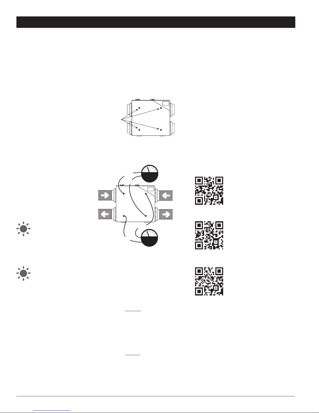
Step 4: Remove the (4) four nylon knock out seals located on
the HRV/ERV access door. (Ref fig 11.1)
Fig 11.1
Fresh Air
from Outside
Stale Air
to Outside
Stale Air
from Home
Fresh
Air
Stale
Air
Fresh Air
to Home
Remove all four (4)
nylon knock out seals.
Do not discard.
LOWLOW
LOW
LOW
HIGH
HIGH
HIGH
HIGH
Aspiration
d'air frais
Évacuation
d'air vicié
Aspiration
d'air vicié
Air frais
Air vicié
Distribution
d'air frais
BASBAS
BAS
BAS
HAUT
HAUT
HAUT
HAUT
Enlever les quatre (4)
bouchons de nylon.
Ne pas les jeter.
Pressure / Pression Fresh air / Air frais Stale air / Air vicié
IN. W.G. Pascal CFM L/s CFM L/s
PO. d’eau (Pa) PCM PCM
0.36 90 216 102 - -
0.34 85 209 99 222 105
0.32 80 200 94 214 101
0.30 75 192 91 207 98
0.28 70 183 86 198 93
0.26 65 173 82 189 89
0.24 60 163 77 180 85
0.22 55 153 72 170 80
0.20 50 142 67 159 75
0.18 45 131 62 148 70
0.16 40 119 56 136 64
0.14 35 107 50 124 59
0.12 30 95 45 111 52
0.10 25 82 39 97 46
0.08 20 68 32 83 39
0.06 15 55 26 69 33
0.04 10 55 26 54 25
Balancing chart 2.0Balancing chart 1.5
Pressure / Pression Fresh air / Air frais Stale air / Air vicié
IN. W.G. Pascal CFM L/s CFM L/s
PO. d’eau (Pa) PCM PCM
0.60 149 186 88 187 88
0.58 144 182 86 184 87
0.56 139 177 84 180 85
0.54 135 172 81 176 83
0.52 130 167 79 173 82
0.50 125 162 76 169 80
0.48 120 157 74 165 78
0.46 115 152 72 161 76
0.44 110 146 69 156 74
0.42 105 141 67 152 72
0.40 100 136 64 147 69
0.38 95 130 61 143 67
0.36 90 125 59 138 65
0.34 85 119 56 133 63
0.32 80 113 53 128 60
0.30 75 107 50 123 58
0.28 70 102 48 117 55
0.26 65 96 45 112 53
0.24 60 90 42 106 50
0.22 55 84 40 100 47
0.20 50 78 37 94 44
0.18 45 71 34 88 42
0.16 40 65 31 82 39
0.14 35 59 28 76 36
0.12 30 52 25 69 33
0.10 25 46 22 62 29
0.08 20 39 18 56 26
0.06 15 33 16 49 23
Step 5: Connect the two (2) plastic hoses from the gauge
to the HIGH & LOW balancing pressure taps on the fresh or
stale air side located on the HRV/ERV access door (Ref Fig
11.2 )
Fig 11.2
Fresh Air
from Outside
Stale Air
to Outside
Stale Air
from Home
Fresh
Air
Stale
Air
Fresh Air
to Home
Remove all four (4)
nylon knock out seals.
Do not discard.
LOWLOW
LOW
LOW
HIGH
HIGH
HIGH
HIGH
Aspiration
d'air frais
Évacuation
d'air vicié
Aspiration
d'air vicié
Air frais
Air vicié
Distribution
d'air frais
BASBAS
BAS
BAS
HAUT
HAUT
HAUT
HAUT
Enlever les quatre (4)
bouchons de nylon.
Ne pas les jeter.
Pressure / Pression Fresh air / Air frais Stale air / Air vicié
IN. W.G. Pascal CFM L/s CFM L/s
PO. d’eau (Pa) PCM PCM
0.36 90 216 102 - -
0.34 85 209 99 222 105
0.32 80 200 94 214 101
0.30 75 192 91 207 98
0.28 70 183 86 198 93
0.26 65 173 82 189 89
0.24 60 163 77 180 85
0.22 55 153 72 170 80
0.20 50 142 67 159 75
0.18 45 131 62 148 70
0.16 40 119 56 136 64
0.14 35 107 50 124 59
0.12 30 95 45 111 52
0.10 25 82 39 97 46
0.08 20 68 32 83 39
0.06 15 55 26 69 33
0.04 10 55 26 54 25
Balancing chart 2.0Balancing chart 1.5
Pressure / Pression Fresh air / Air frais Stale air / Air vicié
IN. W.G. Pascal CFM L/s CFM L/s
PO. d’eau (Pa) PCM PCM
0.60 149 186 88 187 88
0.58 144 182 86 184 87
0.56 139 177 84 180 85
0.54 135 172 81 176 83
0.52 130 167 79 173 82
0.50 125 162 76 169 80
0.48 120 157 74 165 78
0.46 115 152 72 161 76
0.44 110 146 69 156 74
0.42 105 141 67 152 72
0.40 100 136 64 147 69
0.38 95 130 61 143 67
0.36 90 125 59 138 65
0.34 85 119 56 133 63
0.32 80 113 53 128 60
0.30 75 107 50 123 58
0.28 70 102 48 117 55
0.26 65 96 45 112 53
0.24 60 90 42 106 50
0.22 55 84 40 100 47
0.20 50 78 37 94 44
0.18 45 71 34 88 42
0.16 40 65 31 82 39
0.14 35 59 28 76 36
0.12 30 52 25 69 33
0.10 25 46 22 62 29
0.08 20 39 18 56 26
0.06 15 33 16 49 23
Note: If the gauge needle drops below zero, reverse the
plastic
hose connections.
Step 6: Press the (+) and (–) buttons on the Duotrol™
simultaneously until you see the yellow light. Once the
indicator light turns yellow and the unit goes to high speed
you are in balancing mode. When in balancing mode the
selector switch on the Duotrol™ becomes the motor selector
switch. INTER (Right Motor = Stale Airflow), CONT (Both
Motors) and OFF (Left Motor = Fresh Airflow)
Step 7: To adjust the (fresh air), select the «OFF» position
on the Duotrol™. Ensure the plastic hoses from the gauge
are connected to the HIGH & LOW balancing pressure taps
on the fresh airflow side located on the HRV/ERV access
door. (Ref Fig 11.2). To adjust the airflow rates, press the
(–) button to decrease or press the (+) button to increase
the airflow rates until you reach the calculated fresh airflow
requirements.
Step 8: To adjust the (stale air)select the «INTER» position
on the Duotrol™. Ensure the plastic hoses from the gauge
are connected to the HIGH & LOW balancing pressure taps on
the stale air side located on the HRV/ERV access door. (Ref
Fig 11.2) To adjust the airflow rates, press the (–) button to
decrease or press the (+) button to increase the airflow rates
until you reach the calculated stale airflow requirements.
Step 9: Once this is completed, you have balanced the
airflow rates of your HRV/ERV. To exit the balancing mode
you must press (+) and (–) buttons on the Duotrol™
simultaneously until solid green LED appears then release.
The indicator light will turn green to indicate normal operation
mode. Seal the (4) four balancing pressure taps with the
nylon knock out seals removed in Step 4.
Step 10: Mark down the balanced air flow rates information
on a label including in the kit. Apply the label to the HRV/ERV
access door for future reference (e.g. date, balance airflow
rate, your name, phone number and business address).
Note: Once the HRV/ERV is balanced, switch to «CONT» on
the Duotrol™ By using (+) and (–) buttons you can set the
continuous speed.
For Balancing Charts,
- Refer to page 16 of this manual
- Visit www.greentek.ca
- Scan QR code with your smartphone
RNC 1.5 Balancing Chart
RNC 2.0 Balancing Chart
RNC 2.0ES Balancing Chart

Page 11
11. BALANCING THE UNIT (RNC 1.0 & RNC12 ONLY)
TOOLS REQUIRED TO
BALANCE THE HRV/ERV
•
A Magnehelic gauge capable of
measuring 0 to 2.0 inch of water
(0 to 500 Pa) and two (2)
plastic hoses.
• A balancing reference chart located
on the HRV/ERV access door panel.
CONSIDERATION WHEN
BALANCING THE HRV/ERV
• Seal all the unit ductwork with tape.
Close all windows and doors.
•
Insure all exhaust devices such as range
hood, dryer and bathroom fans are off.
• That the integrated balancing
dampers located in the collars are
fully open.(Fresh Air damper ref Fig.
11.5, Stale Air damper ref Fig. 11.6)
• Make sure that all filters are clean
and that there is no obstruction in
ductwork
• Make sure that the forced air system
blower is “ON” when connected to an
existing forced air system ductwork.
•
If it is a direct duct system installation
ensure forced air system blower
is “OFF”.
IMPORTANT: Insure the HRV/ERV has
completed the defrost sequence. That
the dehumidistat is deactivated by
turning the round dial to the “OFF”
position, the Range is” NORMAL”, the
mode is “CONT” and the Cycle per Hour
is set at “0/0”.
NOTE: The unit is considered balanced
even if there is a difference of ±10 cfm
(or ± 5 l/s or 17 m³/h) between the two
air flows
Note to installer: For installation
purposes, the RNC 1.0 & RNC12 are
designed with pre-determined airflow
speed values that are stored in memory.
The RNC 1.0 & RNC12 platform are
designed and can be equipped with the
Duotrol™ speed & balancing control
system kit. (Item: 102801) This factory
option must be present to control the
motors independently, when more
accurate airflow settings are required
or for testing purposes. Please contact
Greentek at 1-888-724-5211
for further instructions/information
on this process.
BALANCING PROCEDURES WITH INTEGRATED DAMPERS
Step 1: Place the Magnehelic gauge on a level surface and
adjust the needle to zero.
Step 2: Connect the two (2) plastic hoses to the gauge on
the HIGH & LOW pressure connections.
Step 3: Once the total ventilation requirements are
determined, you can start balancing the HRV/ERV.
(Refer to 1. Ventilation Requirements)
Step 4: Remove the four (4) nylon knock out seals located
on the HRV/ERV access door. (Ref Fig 11.3)
Fig 11.3
Fresh
Air
Stale
Air
Remove all four (4)
nylon knock out seals.
Do not discard.
screw
Front
Stale
Air
HIGHHIGH HIGHHIGH
LOW
LOWLOWLOW
screw
Front
Fresh
Air
Air ViciéAir frais
Enlever les quatre
(4) bouchons
à défoncer de nylon.
Ne pas les jeter.
HAUTHAUT
BAS
BAS
HAUT
HAUT
BAS
BAS
Vis d'adjustement
Devant
Air
vicié
Vis d'adjustement
Devant
Air
frais
Pressure / Pression Fresh air / Air frais Stale air / Air vicié
IN. W.G. Pascal CFM L/s CFM L/s
PO. d’eau (Pa) PCM PCM
0.50 125 - - 161 76
0.53 132 - - 159 75
0.56 139 - - 156 74
0.59 147 - - 153 72
0.62 154 - - 149 70
0.65 162 - - 146 69
0.68 169 - - 142 67
0.71 177 - - 138 65
0.74 184 149 70 133 63
0.77 192 147 69 129 61
0.80 199 144 68 124 59
0.83 207 141 67 119 56
0.86 214 138 65 114 54
0.89 222 133 63 109 51
0.92 229 128 60 103 49
0.95 237 123 58 97 46
0.98 244 116 55 91 43
1.01 252 109 51 85 40
1.04 259 101 48 78 37
1.07 267 93 44 71 34
1.10 274 84 40 64 30
1.13 281 74 35 57 27
1.16 289 64 30 50 24
1.19 296 53 25 42 20
1.22 304 41 19 34 16
1.25 311 29 14 26 12
Step 5: Connect the two (2) plastic hoses from the gauge
to the HIGH & LOW balancing pressure taps on the fresh
or stale air side located on the HRV/ERV access door
(Ref Fig 11.4)
Fig 11.4
Fresh
Air
Stale
Air
Remove all four (4)
nylon knock out seals.
Do not discard.
screw
Front
Stale
Air
HIGHHIGH HIGHHIGH
LOW
LOWLOWLOW
screw
Front
Fresh
Air
Air ViciéAir frais
Enlever les quatre
(4) bouchons
à défoncer de nylon.
Ne pas les jeter.
HAUTHAUT
BAS
BAS
HAUT
HAUT
BAS
BAS
Vis d'adjustement
Devant
Air
vicié
Vis d'adjustement
Devant
Air
frais
Pressure / Pression Fresh air / Air frais Stale air / Air vicié
IN. W.G. Pascal CFM L/s CFM L/s
PO. d’eau (Pa) PCM PCM
0.50 125 - - 161 76
0.53 132 - - 159 75
0.56 139 - - 156 74
0.59 147 - - 153 72
0.62 154 - - 149 70
0.65 162 - - 146 69
0.68 169 - - 142 67
0.71 177 - - 138 65
0.74 184 149 70 133 63
0.77 192 147 69 129 61
0.80 199 144 68 124 59
0.83 207 141 67 119 56
0.86 214 138 65 114 54
0.89 222 133 63 109 51
0.92 229 128 60 103 49
0.95 237 123 58 97 46
0.98 244 116 55 91 43
1.01 252 109 51 85 40
1.04 259 101 48 78 37
1.07 267 93 44 71 34
1.10 274 84 40 64 30
1.13 281 74 35 57 27
1.16 289 64 30 50 24
1.19 296 53 25 42 20
1.22 304 41 19 34 16
1.25 311 29 14 26 12
Step 6: Set the unit on high speed by connecting the Vectra
EHC-1.0 controller to the HRV/ERV, power “ON” and select
the 20MIN/HR operating mode by pressing the “PREF”
button on the Vectra EHC 1.0 control.
ATTENTION: If there is no control present on the RNC 1.0,
will automatically run on a continuous high speed operating
mode.
Step 7:
To adjust the (fresh air), ensure the plastic hoses
from the gauge are connected to the HIGH & LOW balancing
pressure taps on the fresh air side located on the HRV/ERV
access door. (Ref Fig 11.4). Adjust the fresh airflow integrated
balancing damper adjustment screw clockwise until you
reach the calculated fresh airflow requirements. (Ref Fig
11.5 ).
Fig 11.5
Fresh
Air
Stale
Air
Remove all four (4)
nylon knock out seals.
Do not discard.
screw
Front
Stale
Air
HIGHHIGH HIGHHIGH
LOW
LOWLOWLOW
screw
Front
Fresh
Air
Air ViciéAir frais
Enlever les quatre
(4) bouchons
à défoncer de nylon.
Ne pas les jeter.
HAUTHAUT
BAS
BAS
HAUT
HAUT
BAS
BAS
Vis d'adjustement
Devant
Air
vicié
Vis d'adjustement
Devant
Air
frais
Pressure / Pression Fresh air / Air frais Stale air / Air vicié
IN. W.G. Pascal CFM L/s CFM L/s
PO. d’eau (Pa) PCM PCM
0.50 125 - - 161 76
0.53 132 - - 159 75
0.56 139 - - 156 74
0.59 147 - - 153 72
0.62 154 - - 149 70
0.65 162 - - 146 69
0.68 169 - - 142 67
0.71 177 - - 138 65
0.74 184 149 70 133 63
0.77 192 147 69 129 61
0.80 199 144 68 124 59
0.83 207 141 67 119 56
0.86 214 138 65 114 54
0.89 222 133 63 109 51
0.92 229 128 60 103 49
0.95 237 123 58 97 46
0.98 244 116 55 91 43
1.01 252 109 51 85 40
1.04 259 101 48 78 37
1.07 267 93 44 71 34
1.10 274 84 40 64 30
1.13 281 74 35 57 27
1.16 289 64 30 50 24
1.19 296 53 25 42 20
1.22 304 41 19 34 16
1.25 311 29 14 26 12
Fresh
Air
Stale
Air
Remove all four (4)
nylon knock out seals.
Do not discard.
screw
Front
Stale
Air
HIGHHIGH HIGHHIGH
LOW
LOWLOWLOW
screw
Front
Fresh
Air
Air ViciéAir frais
Enlever les quatre
(4) bouchons
à défoncer de nylon.
Ne pas les jeter.
HAUTHAUT
BAS
BAS
HAUT
HAUT
BAS
BAS
Vis d'adjustement
Devant
Air
vicié
Vis d'adjustement
Devant
Air
frais
Pressure / Pression Fresh air / Air frais Stale air / Air vicié
IN. W.G. Pascal CFM L/s CFM L/s
PO. d’eau (Pa) PCM PCM
0.50 125 - - 161 76
0.53 132 - - 159 75
0.56 139 - - 156 74
0.59 147 - - 153 72
0.62 154 - - 149 70
0.65 162 - - 146 69
0.68 169 - - 142 67
0.71 177 - - 138 65
0.74 184 149 70 133 63
0.77 192 147 69 129 61
0.80 199 144 68 124 59
0.83 207 141 67 119 56
0.86 214 138 65 114 54
0.89 222 133 63 109 51
0.92 229 128 60 103 49
0.95 237 123 58 97 46
0.98 244 116 55 91 43
1.01 252 109 51 85 40
1.04 259 101 48 78 37
1.07 267 93 44 71 34
1.10 274 84 40 64 30
1.13 281 74 35 57 27
1.16 289 64 30 50 24
1.19 296 53 25 42 20
1.22 304 41 19 34 16
1.25 311 29 14 26 12
Step 8: To adjust the (stale air), ensure the plastic hoses
from the gauge are connected to the HIGH & LOW balancing
pressure taps on the stale air side located on the HRV/ERV
access door. (Ref Fig 11.4). Adjust the stale airflow integrated
balancing adjustment screw until you reach the calculated
stale airflow requirements. (Ref Fig 11.6).
Fig 11.6
Fresh
Air
Stale
Air
Remove all four (4)
nylon knock out seals.
Do not discard.
screw
Front
Stale
Air
HIGHHIGH HIGHHIGH
LOW
LOWLOWLOW
screw
Front
Fresh
Air
Air ViciéAir frais
Enlever les quatre
(4) bouchons
à défoncer de nylon.
Ne pas les jeter.
HAUTHAUT
BAS
BAS
HAUT
HAUT
BAS
BAS
Vis d'adjustement
Devant
Air
vicié
Vis d'adjustement
Devant
Air
frais
Pressure / Pression Fresh air / Air frais Stale air / Air vicié
IN. W.G. Pascal CFM L/s CFM L/s
PO. d’eau (Pa) PCM PCM
0.50 125 - - 161 76
0.53 132 - - 159 75
0.56 139 - - 156 74
0.59 147 - - 153 72
0.62 154 - - 149 70
0.65 162 - - 146 69
0.68 169 - - 142 67
0.71 177 - - 138 65
0.74 184 149 70 133 63
0.77 192 147 69 129 61
0.80 199 144 68 124 59
0.83 207 141 67 119 56
0.86 214 138 65 114 54
0.89 222 133 63 109 51
0.92 229 128 60 103 49
0.95 237 123 58 97 46
0.98 244 116 55 91 43
1.01 252 109 51 85 40
1.04 259 101 48 78 37
1.07 267 93 44 71 34
1.10 274 84 40 64 30
1.13 281 74 35 57 27
1.16 289 64 30 50 24
1.19 296 53 25 42 20
1.22 304 41 19 34 16
1.25 311 29 14 26 12
Fresh
Air
Stale
Air
Remove all four (4)
nylon knock out seals.
Do not discard.
screw
Front
Stale
Air
HIGHHIGH HIGHHIGH
LOW
LOWLOWLOW
screw
Front
Fresh
Air
Air ViciéAir frais
Enlever les quatre
(4) bouchons
à défoncer de nylon.
Ne pas les jeter.
HAUTHAUT
BAS
BAS
HAUT
HAUT
BAS
BAS
Vis d'adjustement
Devant
Air
vicié
Vis d'adjustement
Devant
Air
frais
Pressure / Pression Fresh air / Air frais Stale air / Air vicié
IN. W.G. Pascal CFM L/s CFM L/s
PO. d’eau (Pa) PCM PCM
0.50 125 - - 161 76
0.53 132 - - 159 75
0.56 139 - - 156 74
0.59 147 - - 153 72
0.62 154 - - 149 70
0.65 162 - - 146 69
0.68 169 - - 142 67
0.71 177 - - 138 65
0.74 184 149 70 133 63
0.77 192 147 69 129 61
0.80 199 144 68 124 59
0.83 207 141 67 119 56
0.86 214 138 65 114 54
0.89 222 133 63 109 51
0.92 229 128 60 103 49
0.95 237 123 58 97 46
0.98 244 116 55 91 43
1.01 252 109 51 85 40
1.04 259 101 48 78 37
1.07 267 93 44 71 34
1.10 274 84 40 64 30
1.13 281 74 35 57 27
1.16 289 64 30 50 24
1.19 296 53 25 42 20
1.22 304 41 19 34 16
1.25 311 29 14 26 12
Step 9: Seal the four (4) balancing pressure taps
with the nylon knock out seals removed in Step 4.
Step 10: Mark down the balanced air flow rates information
on a label including in the kit. Apply the label to the HRV/ERV
access door for future reference (e.g. date, balance airflow
rate, your name, phone number and business address).
For Balancing Charts,
- Refer to page 16 of this manual
- Visit www.greentek.ca
- Scan QR code with your smartphone
RNC 1.0 Balancing Chart
RNC12 Balancing Chart
NOTE: Turning the
damper adjustment
screw clockwise
will reduce the
airflow, turning
counterclockwise will
increase the airflow
NOTE: Turning the
damper adjustment
screw clockwise
will reduce the
airflow, turning
counterclockwise will
increase the airflow

Page 12
CAUTION:
Minimum wire requirements is LVT18 CSA/UL 4 strain to insure proper connection.
12. CONTROLS CONNECTION
RD-2, RD-3P, RD-4P (4 WIRES)
Installation of a RD-Series main wall control with your HRV/ERV will improve comfort and may significantly reduce the product’s energy use.
VECTRA SERIES - MODEL EHC 1.0 & EHC 1.5 (4 WIRES)
Installation of a Vectra Series main wall control with your HRV/ERV will improve comfort and may significantly reduce the product’s energy use.
RNC 1.5 & RNC 2.0 Series
RNC 1.0 & RNC12 only
To Casing
Screw
for Ground
Jumper
JP-4*
2 Relays
LVC Version 1
B
INTERLOCK
COMN.O.N.C.
RLY1
4321
D1
SW3
TIMER
REMOTE
W
B1 GR
GBR
MASTER
PROG
J2
–
+
B
INTERLOCK
COMN.O.N.C.
RLY1
4321
D1
SW3
TIMER
REMOTE
W
B1 GR
GBR
MASTER
PROG
J2
–
+
B
INTERLOCK
COMN.O.N.C.
RLY1
4321
D1
SW3
TIMER
REMOTE
W
B1 GR
GBR
MASTER
PROG
J2
–
+
R
G
R
G
R
G
B
W
R
G
B
W
BGRBGR
B
INTERLOCK
COMN.O.N.C.
RLY1
4321
D1
SW3
TIMER
REMOTE
W
B1 GR
GBR
MASTER
PROG
J2
–
+
RLY2BGWR
Jumper
JP-4*
1 Relay
LVC Version 1
B
INTERLOCK
COMN.O.N.C.
RLY1
4321
D1
SW3
TIMER
REMOTE
W
B1 GR
GBR
MASTER
PROG
J2
–
+
BGWR
B
INTERLOCK
COMN.O.N.C.
RLY1
4321
D1
SW3
TIMER
REMOTE
W
R
B1
G
W
B1 GR
GBR
MASTER
PROG
J2
–
+
R
B1
G
W
COMNCNOB G
INTERLOCK TIMER / MINUTERIE
RB/B1 WG
CONTROL / COMMANDE
R
COMNCNOB G
INTERLOCKTIMER / MINUTERIE
RB/B1 WG
CONTROL / COMMANDE
R
COMNCNOB G
INTERLOCK TIMER / MINUTERIE
RB/B1 WG
CONTROL / COMMANDE
R
COMNCNOB G
INTERLOCK TIMER / MINUTERIE
RB/B1 WG
CONTROL / COMMANDE
R
Terminal Barrier HRV/ERV Connection
Low Voltage
HRV/ERV
Controller
Low Voltage
HRV/ERV
Controller
Low Voltage
HRV/ERV
Controller
Low Voltage
HRV/ERV
Controller
Terminal Barrier HRV/ERV Connection
RD-1 (2 WIRES)
Installation of a RD-Series main wall control with your HRV/ERV will improve comfort and may significantly reduce the product’s energy use.
RNC 1.5 & RNC 2.0 Series RNC 1.0 & RNC12 only
To Casing
Screw
for Ground
Jumper
JP-4*
2 Relays
LVC Version 1
B
INTERLOCK
COMN.O.N.C.
RLY1
4321
D1
SW3
TIMER
REMOTE
W
B1 GR
GBR
MASTER
PROG
J2
–
+
B
INTERLOCK
COMN.O.N.C.
RLY1
4321
D1
SW3
TIMER
REMOTE
W
B1 GR
GBR
MASTER
PROG
J2
–
+
B
INTERLOCK
COMN.O.N.C.
RLY1
4321
D1
SW3
TIMER
REMOTE
W
B1 GR
GBR
MASTER
PROG
J2
–
+
R
G
R
G
R
G
B
W
R
G
B
W
BGRBGR
B
INTERLOCK
COMN.O.N.C.
RLY1
4321
D1
SW3
TIMER
REMOTE
W
B1 GR
GBR
MASTER
PROG
J2
–
+
RLY2BGWR
Jumper
JP-4*
1 Relay
LVC Version 1
B
INTERLOCK
COMN.O.N.C.
RLY1
4321
D1
SW3
TIMER
REMOTE
W
B1 GR
GBR
MASTER
PROG
J2
–
+
BGWR
B
INTERLOCK
COMN.O.N.C.
RLY1
4321
D1
SW3
TIMER
REMOTE
W
R
B1
G
W
B1 GR
GBR
MASTER
PROG
J2
–
+
R
B1
G
W
COMNCNOB G
INTERLOCK TIMER / MINUTERIE
RB/B1 WG
CONTROL / COMMANDE
R
COMNCNOB G
INTERLOCKTIMER / MINUTERIE
RB/B1 WG
CONTROL / COMMANDE
R
COMNCNOB G
INTERLOCK TIMER / MINUTERIE
RB/B1 WG
CONTROL / COMMANDE
R
COMNCNOB G
INTERLOCK TIMER / MINUTERIE
RB/B1 WG
CONTROL / COMMANDE
R
Terminal Barrier HRV/ERV Connection
Low Voltage
HRV/ERV
Controller
Low Voltage
HRV/ERV
Controller
Low Voltage
HRV/ERV
Controller
Low Voltage
HRV/ERV
Controller
Terminal Barrier HRV/ERV Connection
T3 TIMER (3 WIRES)
RNC 1.5 & RNC 2.0
Series
To Casing
Screw
for Ground
Jumper
JP-4*
2 Relays
LVC Version 1
B
INTERLOCK
COMN.O.N.C.
RLY1
4321
D1
SW3
TIMER
REMOTE
W
B1 GR
GBR
MASTER
PROG
J2
–
+
B
INTERLOCK
COMN.O.N.C.
RLY1
4321
D1
SW3
TIMER
REMOTE
W
B1 GR
GBR
MASTER
PROG
J2
–
+
B
INTERLOCK
COMN.O.N.C.
RLY1
4321
D1
SW3
TIMER
REMOTE
W
B1 GR
GBR
MASTER
PROG
J2
–
+
R
G
R
G
R
G
B
W
R
G
B
W
BGRBGR
B
INTERLOCK
COMN.O.N.C.
RLY1
4321
D1
SW3
TIMER
REMOTE
W
B1 GR
GBR
MASTER
PROG
J2
–
+
RLY2BGWR
Jumper
JP-4*
1 Relay
LVC Version 1
B
INTERLOCK
COMN.O.N.C.
RLY1
4321
D1
SW3
TIMER
REMOTE
W
B1 GR
GBR
MASTER
PROG
J2
–
+
BGWR
B
INTERLOCK
COMN.O.N.C.
RLY1
4321
D1
SW3
TIMER
REMOTE
W
R
B1
G
W
B1 GR
GBR
MASTER
PROG
J2
–
+
R
B1
G
W
COMNCNOB G
INTERLOCK TIMER / MINUTERIE
RB/B1 WG
CONTROL / COMMANDE
R
COMNCNOB G
INTERLOCKTIMER / MINUTERIE
RB/B1 WG
CONTROL / COMMANDE
R
COMNCNOB G
INTERLOCK TIMER / MINUTERIE
RB/B1 WG
CONTROL / COMMANDE
R
COMNCNOB G
INTERLOCK TIMER / MINUTERIE
RB/B1 WG
CONTROL / COMMANDE
R
Terminal Barrier HRV/ERV Connection
Low Voltage
HRV/ERV
Controller
Low Voltage
HRV/ERV
Controller
Low Voltage
HRV/ERV
Controller
Low Voltage
HRV/ERV
Controller
Terminal Barrier HRV/ERV Connection
RNC 1.0 & RNC12 only

Page 13
RNC 1.5 & RNC 2.0 Series
RNC 1.5 & RNC 2.0
Series
RNC 1.0 & RNC12 only
13. WIRING DIAGRAMS FOR FURNACE INTERLOCK SYSTEMS
STANDARD FORCED AIR INTERLOCKING WIRING
A relay is normally used when tying a ventilation system to the forced air distribution system. Our Duotrol System is equipped with an internal relay that will activate the
forced air system’ ventilator when there is a demand from the HRV /ERV. The Duotrol System will activate the INTERLOCK relay during the following modes: Continuous,
Override,Recirculation and Defrost. See wiring diagram.
ALTERNATE FORCED AIR INTERLOCKING WIRING
Some forced air system thermostat will activate the cooling system when tied using the «Standard forced air interlocking wiring». If you have identify this type of
thermostat you must proceed with the «Alternate Forced Air Wiring».
Locating the
Wiring Diagram
Note to installer: Wiring Diagram for
the entire line of HRV/ERV Models are
placed on the back of each Exhaust
motor bracket.
CAUTION: Thermostat that control A/C
system must use the Alternate Interlock
Wiring Diagram.
B
INTERLOCK
COMN.O.N.C.
RLY1
4321
D1
SW3
TIMER
REMOTE
W
B1 GR
GBR
MASTER
PROG
J2
–
+CYWRG
B
INTERLOCK
COMN.O.N.C.
RLY1
4321
D1
SW3
TIMER
REMOTE
W
B1 GR
GBR
MASTER
PROG
J2
–
+CYWRG
YWRG
CYWRG
COM NC NO BG
INTERLOCK TIMER
RB/B1W G
CONTROL
R
Terminal Barrier HRV/ERV Connection
COM NC NO BG
INTERLOCK TIMER
RB/B1W G
CONTROL
R
Terminal Barrier HRV/ERV Connection
Forced Air SystemForced Air SystemLow Voltage HRV/ERV Controller
Forced Air
System
Thermostat
Low Voltage HRV/ERV Controller
CYWRG
YWRG
Forced Air
System
Thermostat
B
INTERLOCK
COMN.O.N.C.
RLY1
4321
D1
SW3
TIMER
REMOTE
W
B1 GR
GBR
MASTER
PROG
J2
–
+
CYWRG
B
INTERLOCK
COMN.O.N.C.
RLY1
4321
D1
SW3
TIMER
REMOTE
W
B1 GR
GBR
MASTER
PROG
J2
–
+
CYWRG
YWRG
CYWRG
COM NC NO BG
INTERLOCK TIMER
RB/B1W G
CONTROL
R
Terminal Barrier HRV/ERV Connection
COM NC NO BG
INTERLOCK TIMER
RB/B1W G
CONTROL
R
Terminal Barrier HRV/ERV Connection
Forced Air SystemForced Air SystemLow Voltage HRV/ERV Controller
Forced Air
System
Thermostat
Low Voltage HRV/ERV Controller
CYWRG
YWRG
Forced Air
System
Thermostat
B
INTERLOCK
COMN.O.N.C.
RLY1
4321
D1
SW3
TIMER
REMOTE
W
B1 GR
GBR
MASTER
PROG
J2
–
+CYWRG
B
INTERLOCK
COMN.O.N.C.
RLY1
4321
D1
SW3
TIMER
REMOTE
W
B1 GR
GBR
MASTER
PROG
J2
–
+CYWRG
YWRG
CYWRG
COM NC NO BG
INTERLOCK TIMER
RB/B1W G
CONTROL
R
Terminal Barrier HRV/ERV Connection
COM NC NO BG
INTERLOCK TIMER
RB/B1W G
CONTROL
R
Terminal Barrier HRV/ERV Connection
Forced Air SystemForced Air SystemLow Voltage HRV/ERV Controller
Forced Air
System
Thermostat
Low Voltage HRV/ERV Controller
CYWRG
YWRG
Forced Air
System
Thermostat
Standard forced air wiring diagram
*Before tying the HRV/ERV to a forced air system, always refer to system’s manual or manufacturer.
WARNING:
Always disconnect the unit prior to making any connections. Failure to disconnecting the power could result in electrical shock or can
damage the electronic boards, wall controls and/or unit.
CAUTION:
Minimum wire requirements is LVT18 CSA/UL 4 strain to insure proper connection.

Page 14
14. TROUBLESHOOTING
QUESTION / ITEM DIAGNOSIS / SOLUTION
• HRV/ERV not running • Verify breaker in main electrical panel
• Verify the HRV or ERV is in the ON position
• Verify the all wall controls switch on the HRV or ERV are activated to supply power to the unit
• Unplug HRV or ERV verify if the controller is wired correctly to the connection box on the side of the unit
• Verify main outlet polarization
• Air is too dry • Reduce the humidity level on the controller
• Reduce continuous airflow rate
• Switch ventilation mode from continuous to intermittent
• Humidifier recommended if heating source is a forced air system
• Air too humid • Suggest continuous operation of HRV or ERV
• Increase humidity level on dehumidistat
• Increase continuous airflow rate
• Insufficient ventilation, check capacity
• Internal source of moisture, e.g. heating wood store in basement, possible leaks or poor insulation R-value and or
dryer is venting in basement
• Vibration or noise • Verify that vibration mounting straps, hanging chains or wall bracket is used for hanging the units.
• Verify that flexible duct connections are use between the HRV or ERV and the rigid duct.
• Verify that the motors are operating and are not obscured by any debris
• Insure motor moves freely with turning by hand.
• Cold air • Misplaced supply outlets
• Defrost no operating correctly
• The HRV or ERV not properly balanced
• High airflow on furnace continuous mode
• Insure HRV or ERV is interlock when integrated with forced air system
• Contamination or Pollutants • Insure proper clearance of ventilation hoods from source of contaminants
Refer to section 10. Outside Fresh Air and Exhaust Air Hoods.
• Condensation • Verify that the HRV or ERV is level to insure proper drainage
• Verify that the duct connection are fix and secured with screws to the HRV or ERV.
• Verify the cold side duct connections are fully insulated and that vapor barrier is taped to insure a proper seal.
• Look for signs of crushed section, failing duct straps, puncture vapor barrier, missing insulation.
• Insure proper seal of vapor barrier to outside wall.
• Look for sign of water accumulation/leakage/dripping
• Verify that the drain connection is not kinked; the “P” trap is not to close to unit or obscured with debris.

Page 15
15. MAINTENANCE
All Greentek products are backed by the best limited warranty on the market.
Greentek reserves the rights to modify a product, without prior notice, whether in price, design, color or codes, in order to offer at all times quality products that are highly competitive.
ALWAYS CONSULT YOUR NATIONAL AND LOCAL REGULATIONS BUILDING AND SAFETY CODES.
ROUTINE MAINTENANCE
Seven-Step
Maintenance Schedule
With routine preventative maintenance,
you can avoid unnecessary problems,
ensure the effectiveness of your HRV,
and prolong its life. For additional
specific instructions, refer to your HRV
operating manual or ask the contractor
who installed or services the HRV to
demonstrate the proper maintenance
procedures. 1. Remove access door (fig 17.1 &
17.2) and clean or replace air filters.
Filters, which are located within the
HRV should be cleaned every two
to three months. Filters should be
vacuumed first, then washed with a
mild soap and water. Most washable
filters will last several years before
needing to be replaced.
2. Clean the exterior intake and
exhaust vents of obstructions.Check
the outside vents regularly to ensure
that the screen openings are not
obstructed by grass, bushes, leaves,
snow or other debris.
3. Clean and inspect the heat-
exchange core. Twice a year and
clean it as required (consult your
owner’s manual for instructions on
inspecting and cleaning the core). A
build-up of dust and dirt can restrict
airflow and reduce the efficiency
of your HRV/ERV. After inspection
and cleaning, make sure the core is
replaced right-side-up.
4. Clean the condensate drain and pan.
Twice a year, check the condensate
drain and tubing to ensure that
they are open and free-flowing.
The tubing can be disconnected for
cleaning. The condensate drain must
have a “trap” in the tubing that traps
a quantity of water – to prevent air
from entering the HRV/ERV via this
tubing
5. Service the fans. The fans on the
HRV/ERV’s are designed to operate
continuously without lubrication.
Inspect the blower fans periodically
for dirt on the blades, and remove
it by gently brushing the blades or
using a vacuum cleaner.
6. Clean the grilles and inspect the
ductwork. Clean the grilles when
they are dusty. At least once a year,
visually inspect the ductwork leading
to and from the HRV. Damaged
ducts can lead to condensation
problems, including wet insulation,
water on the floor and, ice build-up.
If the insulation itself is damaged.
7. Arrange for an annual servicing.
Your HRV/ERV should undergo
annual general servicing by a
certified contractor and who is
familiar with your HRV. If possible,
have your furnace and HRV serviced
at the same time; this will result in
less inconvenience and cost than
two separate visits.
WARNING:
BE SURE TO DISCONNECT THE ELECTRICAL
POWER BEFORE SERVICING YOUR SYSTEM

Page 16
Pressure / Pression Fresh air / Air frais Stale air / Air vicié
IN. W.G. Pascal CFM L/s CFM
L/s
PO. d’eau (Pa) PCM PCM
0.60 149 186 88 187 88
0.58 144 182 86 184 87
0.56 139 177 84 180 85
0.54 135 172 81 176 83
0.52 130 167 79 173 82
0.50 125 162 76 169 80
0.48 120 157 74 165 78
0.46 115 152 72 161 76
0.44 110 146 69 156 74
0.42 105 141 67 152 72
0.40 100 136 64 147 69
0.38 95 130 61 143 67
0.36 90 125 59 138 65
0.34 85 119 56 133 63
0.32 80 113 53 128 60
0.30 75 107 50 123 58
0.28 70 102 48 117 55
0.26 65 96 45 112 53
0.24 60 90 42 106 50
0.22 55 84 40 100 47
0.20 50 78 37 94 44
0.18 45 71 34 88 42
0.16 40 65 31 82 39
0.14 35 59 28 76 36
0.12 30 52 25 69 33
0.10 25 46 22 62 29
0.08 20 39 18 56 26
0.06 15 33 16 49 23
WARNING
ELECTRICAL SHOCK HAZARD
Could result in serious injury or death
Disconnect power supply
before servicing this equipment
AVERTISSEMENT
RISQUE D'ÉLECTROCUTION
Pourrait entraîner des blessures graves ou la mort
Débrancher le cordon d’alimentation
avant l’entretient de cet appareil
LB2836
Duct connections / Raccordement des conduits
Balancing chart / Tableau d’équilibrage
Stale air
to outside
Évacuation
d'air vicié
Fresh air
from outside
Aspiration
d'air frais
Stale air
from home
Aspiration
d'air vicié
Fresh air
to home
Distribution
d'air frais
Fresh air
Air frais Air vicié
Stale air
LOW/BASLOW/BAS
LOW/BASLOW/BAS
HIGH/HAUTHIGH/HAUT
HIGH/HAUTHIGH/HAUT
Pressure / Pression Fresh air / Air frais Stale air / Air vicié
IN. W.G. Pascal CFM L/s CFM
L/s
PO. d’eau (Pa) PCM PCM
0.36 90 216 102 - -
0.34 85 209 99 222 105
0.32 80 200 94 214 101
0.30 75 192 91 207 98
0.28 70 183 86 198 93
0.26 65 173 82 189 89
0.24 60 163 77 180 85
0.22 55 153 72 170 80
0.20 50 142 67 159 75
0.18 45 131 62 148 70
0.16 40 119 56 136 64
0.14 35 107 50 124 59
0.12 30 95 45 111 52
0.10 25 82 39 97 46
0.08 20 68 32 83 39
0.06 15 55 26 69 33
0.04 10 55 26 54 25
WARNING
ELECTRICAL SHOCK HAZARD
Could result in serious injury or death
Disconnect power supply
before servicing this equipment
AVERTISSEMENT
RISQUE D'ÉLECTROCUTION
Pourrait entraîner des blessures graves ou la mort
Débrancher le cordon d’alimentation
avant l’entretient de cet appareil
LB2837
Duct connections / Raccordement des conduits
Balancing chart / Tableau d’équilibrage
Stale air
to outside
Évacuation
d'air vicié
Fresh air
from outside
Aspiration
d'air frais
Stale air
from home
Aspiration
d'air vicié
Fresh air
to home
Distribution
d'air frais
Fresh air
Air frais Air vicié
Stale air
LOW/BASLOW/BAS
LOW/BASLOW/BAS
HIGH/HAUTHIGH/HAUT
HIGH/HAUTHIGH/HAUT
Pressure / Pression Fresh air / Air frais Stale air / Air vicié
IN. W.G. Pascal CFM L/s CFM
L/s
PO. d’eau (Pa) PCM PCM
0.44 110 209 99 - -
0.42 105 203 96 - -
0.40 100 198 93 207 98
0.38 95 192 91 201 95
0.36 90 185 87 195 92
0.34 85 178 84 189 89
0.32 80 172 81 183 86
0.30 75 164 77 176 83
0.28 70 157 74 169 80
0.26 65 149 70 161 76
0.24 60 141 67 153 72
0.22 55 133 63 145 68
0.20 50 124 59 136 64
0.18 45 115 54 127 60
0.16 40 106 50 117 55
0.14 35 96 45 107 50
0.12 30 87 41 97 46
0.10 25 77 36 86 41
0.08 20 66 31 75 35
0.06 15 56 26 64 30
0.04 10 45 21 52 25
WARNING
ELECTRICAL SHOCK HAZARD
Could result in serious injury or death
Disconnect power supply
before servicing this equipment
AVERTISSEMENT
RISQUE D'ÉLECTROCUTION
Pourrait entraîner des blessures graves ou la mort
Débrancher le cordon d’alimentation
avant l’entretient de cet appareil
LB2839
Duct connections / Raccordement des conduits
Balancing chart / Tableau d’équilibrage
Stale air
to outside
Évacuation
d'air vicié
Fresh air
from outside
Aspiration
d'air frais
Stale air
from home
Aspiration
d'air vicié
Fresh air
to home
Distribution
d'air frais
Fresh air
Air frais Air vicié
Stale air
LOW/BASLOW/BAS
LOW/BASLOW/BAS
HIGH/HAUTHIGH/HAUT
HIGH/HAUTHIGH/HAUT
Pressure / Pression Fresh air / Air frais Stale air / Air vicié
IN. W.G. Pascal CFM L/s CFM
L/s
PO. d’eau (Pa) PCM PCM
0.50 125 - - 161 76
0.53 132 - - 159 75
0.56 139 - - 156 74
0.59 147 - - 153 72
0.62 154 - - 149 70
0.65 162 - - 146 69
0.68 169 - - 142 67
0.71 177 - - 138 65
0.74 184 149 70 133 63
0.77 192 147 69 129 61
0.80 199 144 68 124 59
0.83 207 141 67 119 56
0.86 214 138 65 114 54
0.89 222 133 63 109 51
0.92 229 128 60 103 49
0.95 237 123 58 97 46
0.98 244 116 55 91 43
1.01 252 109 51 85 40
1.04 259 101 48 78 37
1.07 267 93 44 71 34
1.10 274 84 40 64 30
1.13 281 74 35 57 27
1.16 289 64 30 50 24
1.19 296 53 25 42 20
1.22 304 41 19 34 16
1.25 311 29 14 26 12
Stale air
to outside
Évacuation
d'air vicié
Fresh air
from outside
Aspiration
d'air frais
Duct connections / Raccordement des conduits
Stale air
from home
Aspiration
d'air vicié
Fresh air
to home
Distribution
d'air frais
WARNING
ELECTRICAL SHOCK HAZARD
Could result in serious injury or death
Disconnect power supply before servicing this equipment
COM NC NO B G
INTERLOCK
Terminal barrier / Bornier de raccordement
TIMER / MINUTERIE
R B/B1 W G
CONTROL / COMMANDE
R
LB2835
Door / Porte
Balancing chart / Tableau d’équilibrage
RISQUE D'ÉLECTROCUTION
Pourrait entraîner des blessures graves ou la mort
Débrancher le cordon d’alimentation avant l’entretient de cet appareil
AVERTISSEMENT
Fresh airStale air
Air fraisAir vicié
LOW/BASLOW/BAS LOW/BASLOW/BAS
HIGH/HAUTHIGH/HAUT HIGH/HAUTHIGH/HAUT
Pressure / Pression Fresh air / Air frais Stale air / Air vicié
IN. W.G. Pascal CFM L/s CFM
L/s
PO. d’eau (Pa) PCM PCM
0.98 244 32 15 - -
0.95 237 38 18 - -
0.92 229 44 21 33 16
0.89 222 50 24 39 18
0.86 214 56 26 44 21
0.83 207 61 29 49 23
0.80 199 66 31 54 25
0.77 192 70 33 58 27
0.74 184 75 35 62 29
0.71 177 79 37 66 31
0.68 169 83 39 69 33
0.65 162 86 41 72 34
0.62 154 90 42 75 35
0.59 147 93 44 78 37
0.56 139 95 45 81 38
0.53 132 98 46 83 39
0.50 125 100 47 85 40
0.47 117 102 48 88 42
0.44 110 103 49 90 42
0.41 102 105 50 92 43
0.38 95 106 50 95 45
0.35 87 107 50 97 46
0.32 80 - - 100 47
0.29 72 - - 103 49
0.26 65 - - 106 50
0.23 57 - - 109 51
Stale air
to outside
Évacuation
d'air vicié
Fresh air
from outside
Aspiration
d'air frais
Duct connections / Raccordement des conduits
Stale air
from home
Aspiration
d'air vicié
Fresh air
to home
Distribution
d'air frais
WARNING
ELECTRICAL SHOCK HAZARD
Could result in serious injury or death
Disconnect power supply before servicing this equipment
COM NC NO B G
INTERLOCK
Terminal barrier / Bornier de raccordement
TIMER / MINUTERIE
R B/B1 W G
CONTROL / COMMANDE
R
LB3080
Door / Porte
Balancing chart / Tableau d’équilibrage
RISQUE D'ÉLECTROCUTION
Pourrait entraîner des blessures graves ou la mort
Débrancher le cordon d’alimentation avant l’entretient de cet appareil
AVERTISSEMENT
Fresh airStale air
Air fraisAir vicié
LOW/BASLOW/BAS LOW/BASLOW/BAS
HIGH/HAUTHIGH/HAUT HIGH/HAUTHIGH/HAUT
RNC 1.5 Balancing Chart RNC 2.0 Balancing Chart RNC 2.0ES Balancing Chart
RNC 1.0 Balancing Chart RNC12 Balancing Chart
16. BALANCING CHARTS
IMPORTANT: THE BALANCING CHART IS LOCATED ON THE HRV/ERV ACCESS DOOR
50 Kanalflakt Way., Bouctouche, NB E4S 3M5
1-888-724-5211 Fax 1-866-426-7430
www.greentek.ca
This manual suits for next models
4
Table of contents
Other Greentek Fan manuals
Popular Fan manuals by other brands

Greenheck
Greenheck TAUB-CA Installation, operation and maintenance

Infiniton
Infiniton IF-16SP user manual

Ellington
Ellington E-BAS54CH5LKRW instructions

Emerson
Emerson MAYA ZEN CF750ORB00 owner's manual

Fanimation
Fanimation Zonix FP4620 Series Specification sheet

Salda
Salda RIS 1900VE EC 3.0 Technical data

Lindab
Lindab Plexus Series Installation instruction

Progress Lighting
Progress Lighting AirPro P2548 installation manual

Casablanca
Casablanca Silhouette II owner's manual

flowair
flowair KM EL LITE Technical documentation operation manual

Airius
Airius PEARL S1 OPERATING AND INSTALLATION Manual

Maico
Maico ECA 120 SERIES Mounting and operating instructions