GreenValley LiAir 250 PRO User manual

GVI-2021112906
1
LiAir 250 PRO
UAV LiDAR System User Guide
COPYRIGHT © 2017-2021 GreenValley International Inc.
GreenValley International Inc. (GVI) reserves all rights for the final explanation, and at its

GVI-2021112906
2
sole discretion, to change, modify, and remove portions of this document.
No part of this document may be reproduced or transmitted in any form or by any means,
electronic, mechanical, photocopying, recording, or otherwise, without prior written
permission of GreenValley International Inc.
GreenValley International Inc.
2120 University Ave. Ste. 210
Berkeley, CA. 94706
USA
+1 510.345.2899
info@greenvalleyintl.com
www.greenvalleyintl.com
Content
About This Guide .................................................................................................................3
Read This First.....................................................................................................................4
Important Notices .........................................................................................................4

GVI-2021112906
3
1. LiAir 250 PRO System..................................................................................................6
1.1About .......................................................................................................................6
1.2 System Basics........................................................................................................8
1.3 System Principles...................................................................................................9
1.4 Technical Specification ...........................................................................................9
2. LiAir 250 PRO System Components..........................................................................11
2.1 Inertial navigation system.....................................................................................11
2.1.1 GNSS .........................................................................................................11
2.1.2 IMU.............................................................................................................11
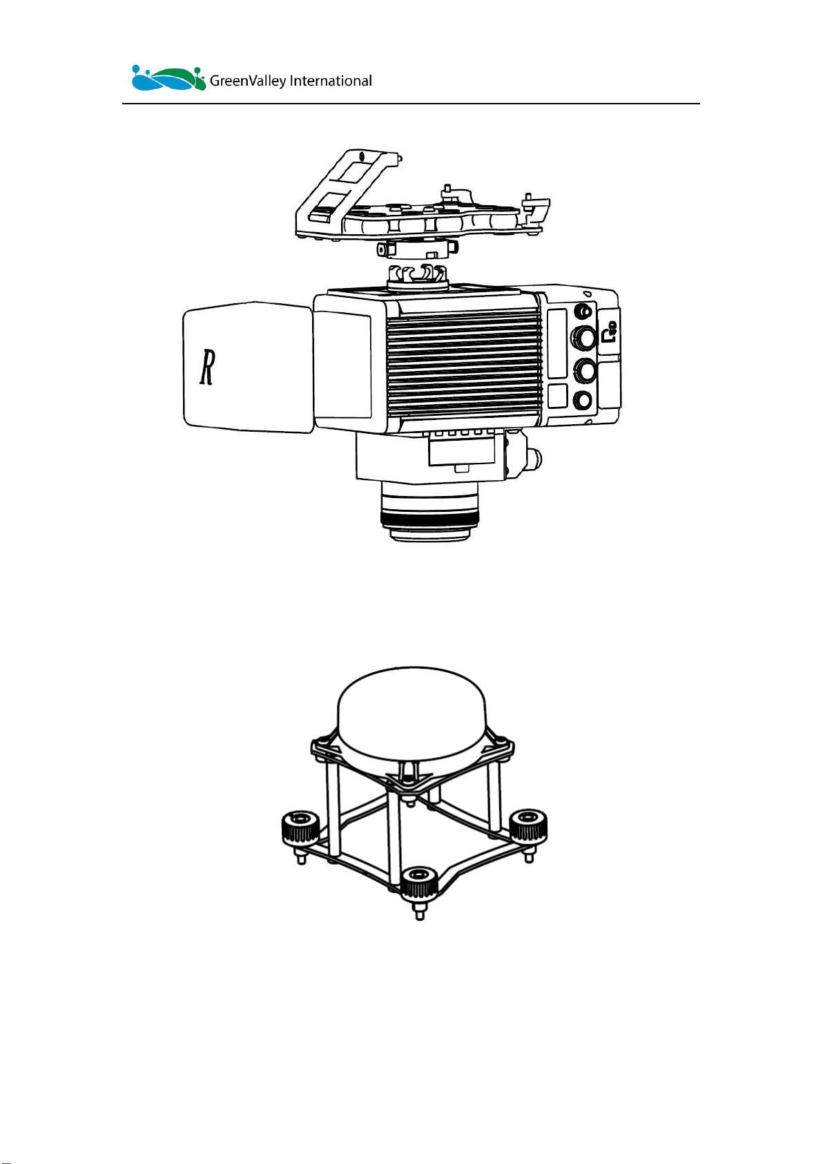
2.2 Laser Scanner ......................................................................................................11
2.3 Control and Storage Unit......................................................................................13
2.4 Camera Unit (Standard Module) ..........................................................................14
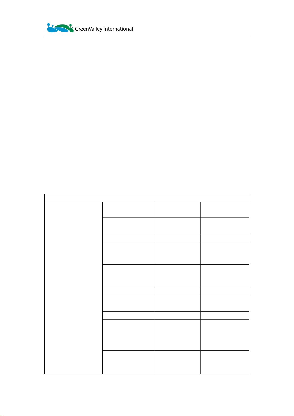
3. Ground GPS Base Station (Optional)............................................................................15
3.1 Introduction...........................................................................................................15
3.2 Base station setup and operation process...........................................................16
3.2.1 Data collection............................................................................................16
3.2.2 Data download ...........................................................................................17
4. Data Storage and Download .........................................................................................18
4.1 Data Storage ........................................................................................................18
4.2 Camera Data Download.......................................................................................19
5. Special Notes.................................................................................................................19
Operation Notice & Equipment Maintenance.............................................................20
About This Guide
This document is a general introduction and operation guide for GVI’s LiAir 250 PRO UAV
As we continue to update and improve the product, you may find some differences
between the contents of this document and your LiAir 250 PRO system. We will
diligently update this guide as the product changes.

GVI-2021112906
4
LiDAR mapping/survey systems.
Please check with GVI for the latest release of this guide and contact GVI support at
suppprt@greenvalleyintl.com if you have any questions.
Read This First
Important Notices
1. LiAir 250 PRO systems use Class 1 (IEC60825-1:2014) eye-safe laser
sensors. If you have any concerns, please contact GVI for details.
STOP! PLEASE READ THIS SECTION CAREFULLY BEFORE USING THE PRODUCT!

GVI-2021112906
5
2. System operator must be at least 18 years old.
3. Do not use the system when there is obvious noise, alarm sound, or damage, and
contact GVI for maintenance in time. Forced use may cause permanent damage to
the system.
4. Follow including but not limited to the operating instructions, suggestions, warnings,
or precautions provided in this manual.
5. The applicable voltage of the system is 11~32V DC, and the typical power is 25W.
Please do not use any power supply outside the applicable voltage range to prevent
danger and damage to the system.
6. Keep the power supply, GPS, network cable, and other connector ports clean and
dry, and do not insert objects other than the docking connector.
7. Please do not disassemble or install the system without authorization, do not
replace parts provided by GVI without authorization, to avoid danger and damage to
the system. If you need to disassemble any part of the system, please contact GVI
and proceed under the guidance of the technical engineer.
8. This system is a high-precision instrument, please handle it gently. It should be
stored and transported in the protective case provided with the system at the time of
purchase or in a productive case authorized for use by GVI.
9. The product should be stored in a cool and dry place. It should be cleaned up after
each use. The power must be turned off during cleaning. Do not clean it directly with
water.

GVI-2021112906
6
10. The working temperature of the system is -10℃~+40℃. Exceeding/below the
suggestion temperature range may cause erroneous measurement results, data loss,
or equipment damage.
11. Before using the system, please ensure that the operating environment is far away
from electromagnetic interference sources. For specific standards, please refer to the
user tutorial.
12. There are corresponding specifications for battery use and storage. For details,
please refer to the lithium battery use/storage specifications.
13. After the equipment is scrapped, please do not throw it directly into the trash bin.
It can be sent back to GVI for disposal or dealt with it in accordance with local
regulations on recycling and disposal of waste electronic products.
1.LiAir 250 PRO System
1.1About
The LiAir 250 PRO UAV LiDAR system is lightweight professional equipment developed for
multiple platforms. It integrates a LiDAR scanning system, an inertial navigation system, and a
control system. It can collect high-precision point cloud data in real-time, dynamically, and
massively, with the option of on-board imaging and photogrammetric information. It is widely
used in the acquisition of 3D spatial information in the fields of surveying and mapping, power,
forestry, agriculture, land (urban) planning, geological disasters, and mining industries.
There may be additional notices and warnings placed throughout parts
of this document. Read each notice and warning carefully and please
follow the instructions.

GVI-2021112906
7
Figure 1 LiAir250 PRO system
Weight:135g

GVI-2021112906
8
Weight:149g
Weight:1860g
1.2 System Basics
LiAir250 PRO is comprised mainly of three major components: LiDAR scanning system, inertial
navigation system, and control & storage system, including:
(1) A GPS receiver used to measure the spatial position of the LiDAR signal transmission
reference point;
(2) The attitude measurement unit used to measure the attitude parameters of the main optical
axis of the scanning, that is, the inertial navigation unit;
(3) A laser ranging unit used to measure the distance between the LiDAR signal emission
reference point and the ground laser foot point, which is the core part of the entire integrated
system, that is, the laser scanner;
(4) A storage control system, used for data storage, system control, and controlling the

GVI-2021112906
9
parameter adjustment, data collection, and downloading functions of the system;
(5) The power supply system is used to supply power to the system.
1.3 System Principles
The inertial measurement unit(IMU)obtains the position and attitude that meet the
accuracy requirements and accurately transmits it to the laser scanner, which is a high-
speed rotating laser scanner.
According to the range information and the rotation angle, the coordinates of each laser
point are quickly calculated, stored in the storage control unit.
1.4 Technical Specification
LiAir 250 PRO Specifications
LiDAR Unit
Max. Scan Range
330m@80@;
170m;ρ≥20%
RIEGL standard
parameters
Relative Accuracy
10mm
RIEGL standard
parameters
System Accuracy
±3cm
AGL:80M,8M/S, FOV 60
Scan Rate
200,000 points/sec
Refer to the miniVUX-
3UAV standard
(mini1-mini2)
Laser Pulse Repetition
Rate
300kHz
Refer to the miniVUX-
3UAV standard
(mini1-mini2)
FOV
360°
Best FOV 90°
Scanning Method
Channel
Parallel line scanning,
even point density
Protection Class
IP54
IP 44
Weight
2 kg
Excluding shock
absorption structure,
camera (300g) and
accessories
Max. Number of
Targets per Pulse
5
Refer to the miniVUX-
3UAV standard
(mini1-mini2)

GVI-2021112906
10
Temperature Range
-10°C up to +40°C
(operation)
Refer to the miniVUX-
3UAV standard
(mini1-mini2)
Integrated Navigation
System
IMU
APX-15 UAV
Refer to APX 15
standard, APX 20 (IMU
90) is optional
IMU Data Rate
200Hz
Measurement Range:
±6g/±300dps
True Heading(deg)
RTK 0.18
Refer to APX 15
standard
APX 20 (IMU 90) is
optional
Post-Processed 0.08
Poll & Pitch (deg)
RTK 0.03
Post-Processed 0.025
Camera
Number of Pixels
(Effective)
24.3 MP
SONY A7R4 is optional
Focal Length
24mm
Storage
128 GB
Weight
0.3 kg
Key Parameters
System power
supply
12-32V
XT30 standard interface
supports OSDK power
supply
UAV Platform
DJI M300 RTK PRO
Adapters can be
customized for other
UAVs
Flight Time
25mins, Max.30mins
System Storage
Built-in 28GB
External SD card
128GB
Provide more storage
solutions
Control Method
WEB UI
Supports Wi-Fi
connection via browser
(mobile phone,laptop)
GPS
Support Trimble RTX
service
Global coverage of 2-
3cm positioning
technology, subscription
service is required
GPS Antenna
Single Antenna
IMU built-in magnetic
compass
Multi-platform
Support
Airborne
Vehicle-mounted
Optional vehicle holder,
support DMI free
operation

GVI-2021112906
11
2. LiAir 250 PRO System Components
2.1 Inertial navigation system
The attitude positioning system is formed by GNSS, IMU, and attitude processing software.
Its main function is to provide the position and attitude information of the LiDAR system
through GNSS and IMU data processing.
2.1.1 GNSS
Global satellite navigation systems mainly include GPS navigation systems (USA), Galileo
(Europe), Beidou navigation systems(China), and GLONASS (Russia).
2.1.2 IMU
IMU: Inertial measurement unit, composed of a high-precision 3-axis gyroscope and
accelerometers in the directions of 3 coordinate axes. It is also the reference center of the
entire lidar system. Its main advantage is that it can obtain the attitude and coordinate
position in real-time without external reference.
Main components: gyroscope + accelerometer + magnetic compass
We have built-in a 3-axis MEMS gyroscope, 3-axis built-in MEMS accelerometer, electronic
magnetic compass, and GNSS receiver. Through a new generation of satellite/inertial
integrated navigation algorithm, it can provide accurate, high real-time, and reliable multi-
parameter navigation information.
Note: Do not install antennas or coaxial cables under lightning storms.
2.2 Laser Scanner
The laser scanner is the core of the system. The LiDAR uses the laser as the emitting light

GVI-2021112906
12
source and the photoelectric detection sensor as the receiving element. The distance and
angle are measured and recorded according to the principle of laser ranging to determine
the orientation information of the measured object.
The transmitter in the LiDAR emits an ultra-short light pulse hitting the object and diffusely
reflected back to the receiver. The speed of light is known. The distance between the target
object and the sensor is calculated by the flight time of the laser beam in the air.
LiDAR distance formula: 𝑆 = 1
2× 𝑐 × ∆𝑡 (1)
* S is the distance from the sensor to the target, c is the speed of light, and △t is the
laser round-trip time
Riegl miniVUX-3UAV is a special LiDAR for light and small UAVs, which uses waveform
digitization and real-time waveform processing technology for high-speed data acquisition.
Scanning through the rotating mirror allows 360° freely adjustable laser scanning field of
view, and collection of complete surrounding environment data. At the same time, it has a
multi-target detection function, and each laser beam has up to 5 target returns.
Figure 2 Riegl miniVUX-3UAV
Laser scanner specifications:
Scanning Mechanism
Rotating mirror

GVI-2021112906
13
Scan Range
0.3 m ~ 250 m (@reflectivity≥60%)
Accuracy
± 15mm
Precision
10mm
Laser Pulse Repetition Rate
10Hz~300Hz
Angle Measurement Resolution
0.001°
Measurement Rate
200,000Pts/sec
FOV (horizontal)
360°
Laser Product Classification
Class 1 Eye-safe
Interfaces
WLAN IEEE802.11, RS232
Power Supply Input Voltage
11 - 34 V DC / typ.
Consumption
18 W @ 100 scans/sec
Temperature Range
-10°C up to +40°C (operation) / -20°C up to +50°C (storage)
Note:
The laser scanner cannot be pointed at by direct strong light (including the beam of two
sensors), to prevent the high-intensity laser from damaging the receiving sensor.
2.3 Control and Storage Unit
The main functions of the control and storage unit:
(1) Ground control information and accurately transmit instructions to the corresponding
sensors.
(2) Control and coordinate the normal operation of each sensor.
(3) Data storage: The device has a built-in storage of 25GB and supports SD card data storage
(capacity depends on the size of the SD card) for storing lidar data, inertial measurement data,
and log information.

GVI-2021112906
14
Figure 3 Control and storage unit interfaces
The main interface and panel indicator of the control and storage unit:
1. LED indicator: system power supply status.
2. Wi-Fi antenna: the location of the Wi-Fi antenna of the system
3. SD card: The current device uses a single SD card data storage mode
4. GPS: GPS connection dedicated SMA interface
5. PWR: power supply interface for the overall equipment, 12-32V power supply
6. CAM: dedicated to camera exposure feedback control
Control and storage unit LED light explanation
LED light
Status
Explanation
System
Uniform flashing Blue0.5Hz
POST, not synchronized
Stable Blue
Scanner synchronization is normal
Rapid flashing Blue2Hz
Start data recording
2.4 Camera Unit (Standard Module)
Modified Sony CAMREA is integrated on LiAir 250 PRO.

GVI-2021112906
15
Camera Specifications
Model
Key Specs.
Parameter
Sony A6000
Sensor type
APS-C type (23.5*15.6mm)
Lens
16 mm fixed focal length lens
Effective pixels
24.3 megapixels
Image Sensor Type
COMS
Exposure Mode
Timing
Weight
0.3 kg
3. Ground GPS Base Station (Optional)
The main function of the ground GPS base station is to observe the same point for a long time,
thereby having a high single-point accuracy as a differential reference for the UAV mobile
station.
GPS base station composition: GPS antenna + GPS receiver + power supply
3.1 Introduction
Figure 4 Base station main body view
1—Power interface (9-30V, 0.3A@12V).
2—USB interface: Connect to a computer through a double-headed USB data cable for base
station data copying.

GVI-2021112906
16
3—Base station status indicator: used to indicate the status of the base station.
4—Save button: Base station data storage/end storage function (long press).
5—RTK rubber rod antenna interface.
6—GPS antenna feeder interface: connect the GPS antenna to the base station through the
feeder cable.
7—RTK rubber rod antenna.
Detailed Instruction for the Base Station Indicator lights:
LED
Status
Explanation
Stable Red
The power supply is normal.
Flashing Red
The power supply voltage is low, the battery needs to be replaced.
Stable Blue
Start storing GPS location information.
Flashing Blue
System SD card installation failed or storage space is less than 1G.
Grey
GPS location information storage has not started/has ended.
Stable Green
RTK function is normal.
Stable Orange
The base station location is locked.
Flashing Orange
The base station location is locking.
3.2 Base station setup and operation process
3.2.1 Data collection
Figure 5 Assembly of the Base Station
1. Connect the GPS antenna and external power supply according to the above figure, and

GVI-2021112906
17
power on;
2. Observe that the indicator light is steadily on;
3. Observe that the indicator light is off;
4. Observe that the indicator light is steadily on, which means that the base station has
received the RTK data and is transmitting.
5. Wait for the indicator light to change from slow flashing to steady on, that is, the
location of the base station is successfully locked;
6. Press the button for more than 1 second, and the indicator will turn to a
steady status, that is, the base station starts to store GPS location information;
7. After the data collection is completed, press the button for more than 1 second, the
indicator light will be off, and the GPS location information will stop recording
8. Turn off the power of the base station;
3.2.2 Data download
Figure 6 Connecting the Base Station to a Computer for Data Download
1. Connect the Base Station to a computer via the provided USB cable.
2. The computer should recognize Base Station as an external disk.

GVI-2021112906
18
3. Download the base station file through direct copy.
Note: The base station file name composition in the SD card: UTC time + suffix (log), for
example, 20170810063808.log.
4. Data Storage and Download
4.1 Data Storage
Laser scan data and IMU data are stored inside the device or on the SD card. The project file
is stored in the project storage path set during data collection (\\192.168.0.10\inter) or the data
is copied through the SD card.
Figure 7 Project file examples
01_IMU_RAW: This folder is used to store IMU raw data (*.T04).
02_SCANNER_RAW: This folder stores laser data.
03_CAM_EIF: Customized camera feedback file (the non-customized folder is empty)
04_SYS_LOG: This folder stores system log files.
05_CAM_RAW: This folder stores camera files (not common to all devices).
LiAir 250 PRO SN2222989.cal: This file is the calibration parameter file of the device.
Note: data download via both Wi-Fi and network cable is supported. SD card data can be

GVI-2021112906
19
directly accessed through the network for data management on the desktop.
Figure 8 Direct access to SD card via Wi-Fi
4.2 Camera Data Download
The camera data is stored in the camera's SD card, and the image data download can be completed by
removing the camera's SD card directly.
(1) Take out the SD card of the camera.
(2) Connect the SD card to the computer, create a new folder named "Images->Cam1" under the Cam
folder in the project folder. And copy all the images collected in the SD card to the folder "Cam1".
Note: Only copy the image files, do not cut any system files. After the device is powered on, it will perform
a self-check. When copying images, you can skip the self-check photos or delete the self-check photos
after the copy is complete.
5. Special Notes
Here are some special notes to pay attention to while operating LiAir V70. GVI has compiled
these notes based on experiences and feedback from customers. The following points out
details that seem small or insignificant but can, however, lead to issues that may be difficult
or impossible to rectify post-mission if left unchecked.

GVI-2021112906
20
Operation Notice & Equipment Maintenance
-The LiAir250 PRO system integrates several high-precision instruments. Please
handle it with care.
-Avoid direct impact to the system. Always store all items properly in the protective
case before transporting. Do not move or transport the system unprotected.
-This product should be stored and transported in the protective case provided by
or authorized for use by GVI.
-Do NOT scratch the Laser Scanner Lens.
-Ensure the Laser Scanner Lens surface is clean before the mission. Only
clean the lens with special cleaning agents for high-precision measurement
instruments and optics with a soft cloth.
-Clean the product thoroughly after each use. Use only proper cleaning agents for
the scientific instrument.
-Pull the power off softly and properly disconnect all batteries, antennas, and
cables after use.
-Please perform a power-on test if the machine is not used for more than one
month.
-Do NOT operate the system in rain, harsh environments, and outside its safe
temperature range.
-System safe operating temperature: -10℃ to + 40℃.
-Storage temperature: -20℃ to + 50℃.
-This product is NOT water-proof. Do NOT operate in rain or snow. Water damage
is NOT covered by the Product Warranty. When not in use, store the product in a
cool and dry environment.
Table of contents
Other GreenValley Measuring Instrument manuals
Popular Measuring Instrument manuals by other brands

Rohde & Schwarz
Rohde & Schwarz R&S SMW-K548 user manual

INTEGRA Metering
INTEGRA Metering AMFLO SONIC UFA-280 Mounting and operating instructions

Interacoustics
Interacoustics Luna Instructions for use

Emco
Emco V-20 operating manual

CDI
CDI TRAXALL 770 user guide

Major tech
Major tech TRUERMS MTD80 instruction manual