accessories. Inspect appliance cord periodically,
and if damaged, have it repaired by an authorized
service facility. Inspect extension cords periodically
and replace if damaged. Keep handles dry, clean,
and free from oil and grease. Failure to do so can
cause serious injury.
• Check damaged parts before using the appliance, a
guard or other part that is damaged should be
carefully checked to determine that it will operate
properly and perform its intended function. Check
for alignment of moving parts, binding of moving
parts, breakage of parts, damaged mountings, and
any other condition that may affect its operation. A
guard or other part that is damaged should be
properly repaired or replaced by an authorized
service center unless indicated elsewhere in this
manual.
• Do not charge appliance in rain, or in wet locations.
• Remove or disconnect battery before servicing,
cleaning or removing material from the gardening
appliance.
•Use appliances only with specifically designated
battery packs. Use of any other battery packs may
create a risk of injury and fire. Use only Greenworks
GLW300 / GLW600 batteries or other BAB series.
• Recharge only with the charger specified by the
manufacturer. A charger that is suitable for one type
of battery pack may create a risk of fire when used
with another battery pack. Use only Greenworks GC
400 charger or other CAB series.
•When battery pack is not in use, keep it away from
other metal objects, like paper clips, coins, keys,
nails, screws or other small metal objects, that can
make a connection from one terminal to another.
Shorting the battery terminals together may cause a
fire.
• Under abusive conditions, liquid may be ejected
from the battery; avoid contact. If contact
accidentally occurs, flush with water. If liquid
contacts eyes, additionally seek medical help. Liquid
ejected from the battery may cause irritation or
burns.
• Do not use a battery pack or appliance that is
damaged or modified. Damaged or modified
batteries may exhibit unpredictable behavior
resulting in fire, explosion or risk of injury.
• Do not expose a battery pack or appliance to fire or
excessive temperature. Exposure to fire or
temperature above 265 °F (130 °C) may cause an
explosion.
• Do not dispose of the batteries in a fire. The cells
may explode. Check with local codes for possible
special disposal instructions.
• Do not open or mutilate the batteries. Released
electrolyte is corrosive and may cause damage to
the eyes or skin. It may be toxic if swallowed.
• Exercise care in handling batteries in order not to
short the battery with conducting materials such as
rings, bracelets, and keys. The battery or conductor
may overheat and cause burns.
• Follow all charging instructions and do not charge
the battery pack or appliance outside of the
temperature range specified in the instructions.
Charging improperly or at temperatures outside of
the specified range may damage the battery and
increase the risk of fire.
• Have servicing performed by a qualified repair
person using only identical replacement parts. This
will ensure that the safety of the product is
maintained.
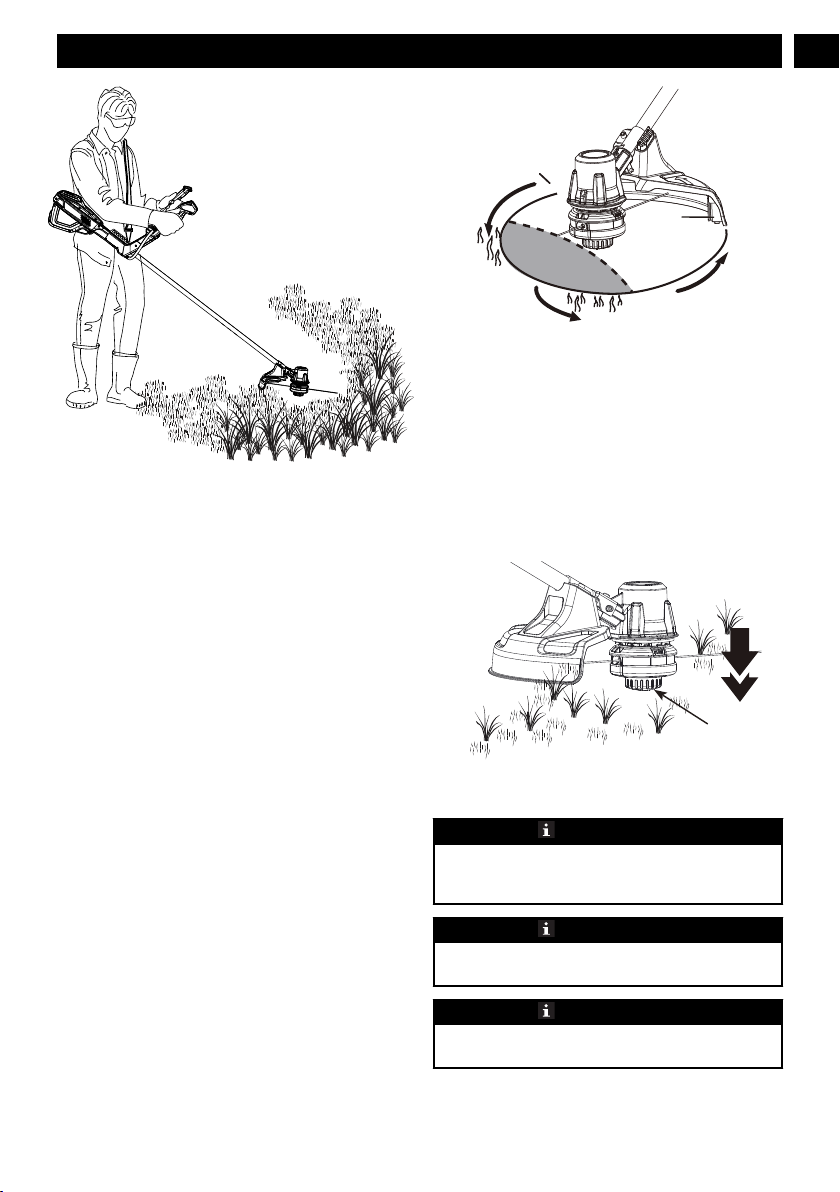
• Keep guards in place and in working order.
• Keep hands and feet away from cutting area.
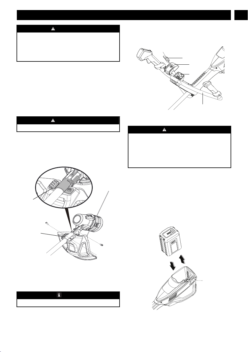
• Disconnect the battery pack from the appliance
before making any adjustments, changing
accessories, or storing appliance. Such preventive
safety measures reduce the risk of starting the
appliance accidentally.
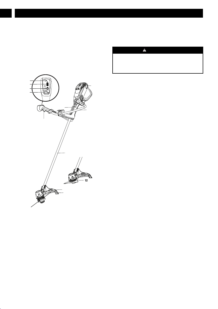
• Use only with the nylon cutting line of 0.080" (2.0
mm) diameter. Do not use heavier lines than
recommended by the manufacturer and line
materials of other types – for example, metal wire,
rope, and the like.
SAVE THESE INSTRUCTIONS
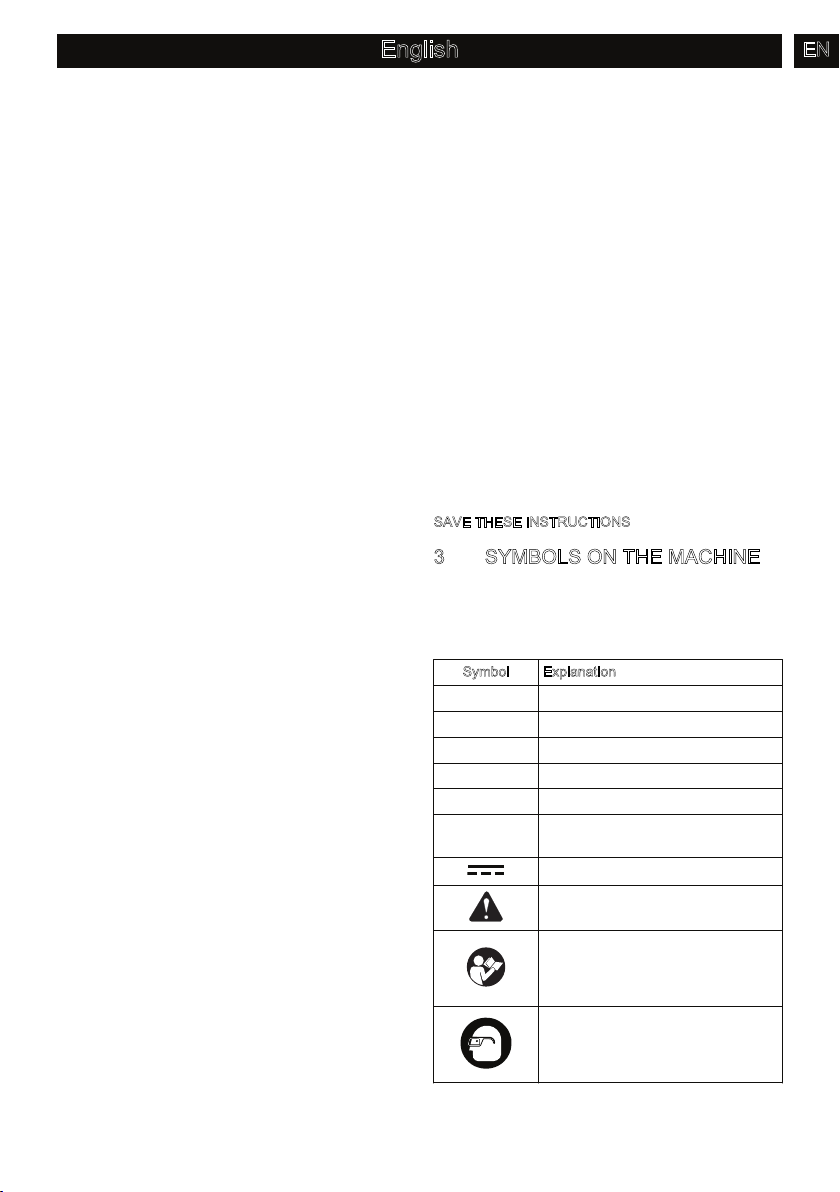
3SYMBOLS ON THE MACHINE
Some of the following symbols can be used on this
machine. Please study them and learn their definition.
Proper interpretation of these symbols will let you
operate the tool better and safer.
Symbol Explanation
V Voltage
A Current
Hz Frequency (cycles per second)
WPower
min Time
/min Revolutions, strokes, surface speed,
orbits etc., per minute
Direct current
Precautions that involve your safety.
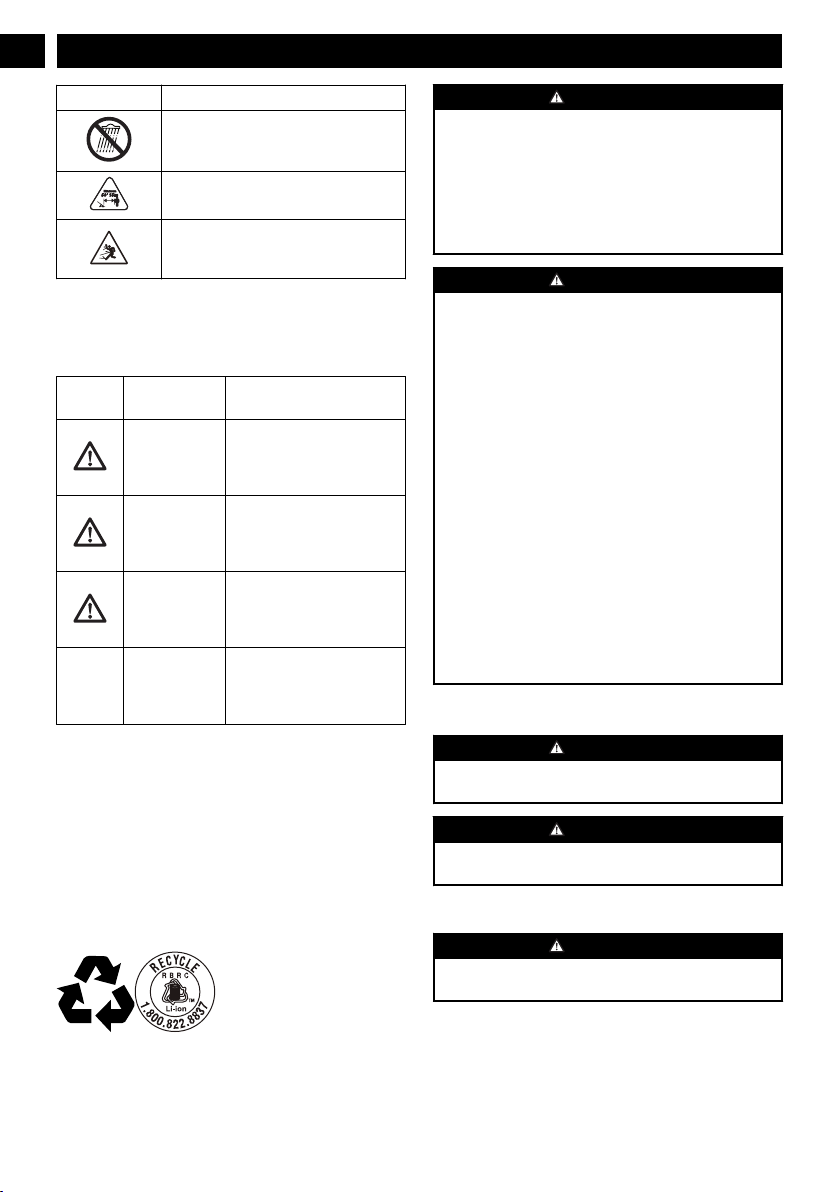
Read and understand all instructions
before you operate the machine, and
follow all warnings and safety instruc-
tions.
Always wear safety glasses with side
shields marked to comply with ANSI
Z87.1 when you operate this ma-
chine.
3
English EN