GreenWorks GTL9526 User manual

1.
CUA101
2. 3.
6.
5.
4.
1
3
6
8
12
2
6
7
4
5
4
5
14
3

CUA101
GTL9526
OPERATOR MANUAL / BEDIENUNGSHANDBUCH / MANUAL DEL OPERARIO /
MANUALE DELL’OPERATORE / MANUEL OPÉRATEUR / MANUAL DE UTILIZAÇÃO /
GEBRUIKSAANWIJZING / РУКОВОДСТВО ОПЕРАТОРА / KÄYTTÖOPAS /
ANVÄNDARHANDBOK / BRUKERVEILEDNING / BRUGSVEJLEDNING / INSTRUKCJA
UŻYTKOWNIKA / NÁVOD K OBSLUZE / NÁVOD NA OBSLUHU / Uporabniški priročnik /
PRIRUČNIK ZA RUKOVANJE / HASZNÁLATI ÚTMUTATÓ / MANUAL DE UTILIZARE /
РЪКОВОДСТВО НА ОПЕРАТОРА / ΕΓΧΕΙΡΙΔΙΟ ΧΡΗΣΗΣ / / KULLANIM
KILAVUZU / / OPERATORIAU VADOVAS / LIETOTĀJA ROKASGRĀMATA /
KASUTUSJUHEND
OriginalInstructions / Übersetzung der Originalanweisungen/ Traducciónde las instrucciones originales/ Traduzione delle istruzioni originali/ Traductiondes
instructions d'origine/ Traduzidoa partir das instruções originais/ Vertaling van de originelegebruiksaanwijzing/ Переводоригинальных инструкций/
Alkuperäisten ohjeiden käännös/ Översättning av originalinstruktionerna/ Produsentens instruksjoner / Oversættelse af de originale vejledninger/ Tłumaczenie
oryginalnej instrukcji / Překlad originálního návodu/ Prekladoriginálneho návodu / Prevodoriginalnih navodil/ Prijevod izvornih uputa/ Az eredeti utasítás
fordítása/ Traducere a instrucțiunilor originale/ Превод на оригиналните инструкции / Αυθεντικέςοδηγίες/ / Orijinal
Talimatların Tercümesi // Originalių instrukcijųvertimas/ Instrukcijutulkojums no oriģinālvalodas/ Originaalkasutusjuhendi tõlge

1 Description.........................................4
1.1 Intended use.......................................................4
1.2 Overview........................................................... 4
2 Safety.................................................. 4
3 Installation......................................... 4
3.1 Unpack the machine.......................................... 4
4 Applications....................................... 5
4.1 Start the machine............................................... 5
4.2 Stop the machine............................................... 5
4.3 Narrow cultivating width...................................5
4.4 Operation tips.................................................... 5
5 Maintenance.......................................5
5.1 Clean the machine............................................. 5
6 Store the machine..............................5
7 Troubleshooting.................................6
8 Technical data....................................6
9 Warranty............................................6
10 EC Declaration of conformity..........6
3
English EN

1 DESCRIPTION
1.1 INTENDED USE
The battery-powered cultivator is intended for loosening of
soil in an open garden area. This product is not intended for
commercial use.
1.2 OVERVIEW
Figure 1-6
1Upper handle
2Lower handle
3Wing nut
4Bail switch
5Safety lock button
6Wheel assembly
7Ring pin
8Tine A
9Tine B
10 Tine C
11 Tine D
12 Hitch pin
13 Felt
14 Plug connector
2 SAFETY
WARNING
Make sure that you do/obey all safety instructions.
Refer to Safety Manual.
3 INSTALLATION
WARNING
Do not change or make accessories that are not
recommended by the manufacturer.
WARNING
Do not connect the machine to the power supply until you
assemble all the parts.
3.1 UNPACK THE MACHINE
WARNING
Make sure that you correctly assemble the machine before
use.
WARNING
• If the parts are damaged, do not use the machine.
• If you do not have all the parts, do not operate the
machine.
• If the parts are damaged or missing, speak to the service
center.
1. Open the package.
2. Read the documentation in the box.
3. Remove all the unassembled parts from the box.
4. Remove the machine from the box.
5. Discard the box and package in compliance with local
regulations.
3.1.1 INSTALL THE HANDLE
Figure 2.
1. Align the holes on the upper handle with holes on the
lower.
2. Insert the bolts through the handles.
3. Use the wing nuts to tighten them.
3.1.2 INSTALL THE WHEEL
Figure 3.
1. Insert the wheel assembly into the support rod.
2. Align the wheel assembly hole to desired position.
3. Slide bolt through hole and attach hitch pin to bolt.
NOTE
The wheel position of the machine is adjustable.You can
control the depth of operation through adjusting the wheel
position.
NOTE
Wheels can be removed for greater tilling depth.
3.1.3 INSTALL THE TINES
Figure 6.
The cultivator has four tines —two inner tines stamped B and
C and two outer tines stamped A and D. For correct operation
of the unit, the tines must be installed in the correct
orientation.
1. Put the machine on a flat and smooth surface.
2. Place tine C on the tine shaft to the left of the gear box.
The stamped side of the tine should face away from the
gear box.
3. Place tine B on the tine shaft to the right of the gear box.
The stamped side of the tine should face away from the
gear box.
4. Place a felt washer on each side of the tine shaft, and
slide to rest against the inner tines.
5. Place the outer tine D on the left side of the tine shaft.
The stamped side should face in toward tine C.
6. Place the outer tine A on the right side of the tine shaft.
The stamped side should face in toward tine B.
7. To secure the tines to the tine shaft, insert the ring pins
into the holes located on either side of the tine shaft.
NOTE
The unit will not operate properly if the tines are installed
incorrectly. If you notice a problem with the cultivating
operation of the unit, check for proper tine positioning.
4
English
EN

WARNING
The tines and the machine may damage even if you move
the machine with the motor switched off. To prevent the
tines from touching the ground while moving please tilt the
machine.
4 APPLICATIONS
• Breaking up garden soil to prepare seed bed for planting.
• Shallow cultivating to remove weeds.
4.1 START THE MACHINE
Figure 4.
1. Connect the machine into an approved outdoor extension
cable.
2. Push and hold the safety lock button.
3. While you hold the safety lock button, pull the bail switch
toward the handle while you hold the safety lock button.
4. Release the safety lock button.
WARNING
Hold the machine with two hands during operation.
NOTE
Stand behind the machine with the tines on the ground and
the work area clean and free of obstructions.
4.2 STOP THE MACHINE
Figure 4.
1. Release the bail switch to stop the machine.
4.3 NARROW CULTIVATING WIDTH
The two outer tine blades can be removed from the unit to
allow a more narrow cultivating width.
1. Remove the ring pins from the holes on the ends of the
tine shaft.
2. Remove the outside tines and felts from the tine shaft.
3. Place hitch pins in the holes.
4.4 OPERATION TIPS
The cultivator can be used to break up garden soil and
prepare a seedbed for planting. Plan ahead to leave enough
room between the seed rows to allow for machine cultivating
after the plants have grown.
1. Several passes over the same path may be required to
reach the desired depth. Do not try to dig too deeply in
the first pass.
2. If the machine jumps or bucks, allow the unit to move
forward at a slightly faster rate or install wheel assembly.
3. If the cultivator stays and digs in at one spot, try rocking
it from side to side in order to start it moving forward
again.
4. If the soil is very hard, water a few days before
cultivating. Avoid working the soil when soggy or wet.
Wait a day or two after heavy rain for the ground to dry.
5. Shallow cultivating less than 5cm. deep can be used to
disrupt weeds and aerate soil, without injuring nearby
plant roots. It should be done often so that weeds do not
grow large and cause tangling in the tines of the unit.
5 MAINTENANCE
CAUTION
Do not let brake fluids, gasoline, petroleum-based materials
touch the plastic parts. Chemicals can cause damage to the
plastic, and make the plastic unserviceable.
CAUTION
Do not use strong solvents or detergents on the plastic
housing or components.
WARNING
Remove the battery pack from the machine before
maintenance.
5.1 CLEAN THE MACHINE
WARNING
Keep the machine and the motor free of leaves, branches or
excessive oil to prevent fire risks.
• Use a moist cloth with a mild detergent to clean the
machine.
• Clean all moisture with a soft dry cloth.
• Use a small brush to clean the air vents.
6 STORE THE MACHINE
• Clean the machine before storage.
• Make sure that the motor is not hot when you store the
machine.
• Make sure that the machine does not have loose or
damaged parts. If it is necessary, do these steps/
instructions:
• Replace the damaged parts.
• Tighten the bolts.
• Speak to a person of an approved service center.
• Store the machine in a dry area.
• Make sure that children cannot come near the machine.
5
English EN

7 TROUBLESHOOTING
Problem Possible cause Solution
Motor fails to start
when bail switch
is depressed.
Power cord is not
plugged in or con-
nection is loose.
Plug in the power
cord.
Household circuit
breaker is tripped.
Check circuit
breaker.
The machine
smokes during op-
eration.
The machine has
damage.
1. Immediately
stop the ma-
chine.
2. Unplug the
machine.
3. Speak to serv-
ice center.
Motor runs but
tines do not move.
The machine has
damage.
Do not use the ma-
chine and speak to
service center.
The tines are
blocked.
Unplug the ma-
chine then clear
blockage from the
tines.
Gear train failure. Speak to service
center.
8 TECHNICAL DATA
Power 950W
No load speed 320 (±10%) /min
Cultivating path 10'' (26 cm)
Protection degree IPX4
Weight 12.1 kg
Measuered sound pressure level LPA= 78.5 dB(A) ,
KPA= 3 dB(A)
Guaranteed sound power level LWA.d= 93 dB(A)
Vibration 3.2 m/s2
Uncertainty K = 1.5 m/s2
9 WARRANTY
(The full warranty terms and conditions can be found on
Greenworks webpage)
The Greenworks warranty is 3 years on the product, and 2
years on batteries (consumer/private usage) from the date of
purchase. This warranty covers manufacturing faults. A faulty
product under warranty might be either repaired or replaced.
A unit that has been misused or used in other ways then
described in the owner’s manual might be rejected for
warranty. Normal wear, and wear parts are not considered as
warranty. The original manufacturer warranty is not affected
by any additional warranty offered by a dealer or retailer.
A faulty product must be returned to the point of purchase in
order to claim for warranty, together with the proof of
purchase (receipt).
10 EC DECLARATION OF
CONFORMITY
Name and address of the manufacturer:
Name: GLOBGRO AB
Globe Group Europe
Address: Riggaregatan 53, 211 13 Malmö, Sweden
Name and address of the person authorised to compile the
technical file:
Name: Peter Söderström
Address: Riggaregatan 53, 211 13 Malmö, Sweden
Herewith we declare that the product
Category: Cultivator
Model: 27017(CUA101)
Serial number: See product rating label
Year of Construction: See product rating label
• is in conformity with the relevant provisions of the
Machinery Directive 2006/42/EC.
• is in conformity with the provisions of the following
other EC-Directives:
• 2014/30/EU
• 2000/14/EC & 2005/88/EC
• 2011/65/EU & (EU)2015/863
Furthermore, we declare that the following parts, clauses of
harmonised standards have been used:
• EN55014-1; EN55014-2; EN61000-3-2;
EN61000-3-3;EN 62233; EN60335-1; EN709
Conformity assessment method to Annex VI/ Directive
2000/14/EC.
Measured sound pow-
er level:
LWA: 91.6 dB(A)
Guaranteed sound
power level:
LWA.d: 93 dB(A)
Place, date: Malmö,
12.12.2019
Signature: Ted Qu, Quality Director
6
English
EN

7
English EN

1 Beschreibung......................................9
1.1 Bestimmungsgemäßer Gebrauch.......................9
1.2 Übersicht............................................................9
2 Sicherheit........................................... 9
3 Montage..............................................9
3.1 Maschine auspacken..........................................9
4 Anwendungen.................................. 10
4.1 Maschine starten..............................................10
4.2 Maschine anhalten........................................... 10
4.3 Schmale Bearbeitungsbreite............................ 10
4.4 Tipps zur Bedienung........................................10
5 Wartung und Instandhaltung.........10
5.1 Maschine reinigen............................................11
6 Maschine lagern...............................11
7 Fehlerbehebung............................... 11
8 Technische Daten............................. 11
9 Garantie............................................11
10 EG-Konformitätserklärung........... 12
8
Deutsch
DE

1 BESCHREIBUNG
1.1 BESTIMMUNGSGEMÄSSER
GEBRAUCH
Der akkubetriebene Kultivator ist für die Bodenlockerung in
einem offenen Gartenbereich vorgesehen. Dieses Produkt ist
nicht für den kommerziellen Gebrauch bestimmt.
1.2 ÜBERSICHT
Abbildung 1-6
1Oberer Griff
2Unterer Griff
3Flügelmutter
4Bügelschalter
5Sicherheitssperrtaste
6Radsatz
7Ringstift
8Hackstern A
9Hackstern B
10 Hackstern C
11 Hackstern D
12 Anhängestift
13 Filzscheibe
14 Steckverbinder
2 SICHERHEIT
WARNUNG
Stellen Sie sicher, dass Sie alle Sicherheitshinweise
befolgen.
Siehe Sicherheitshandbuch.
3 MONTAGE
WARNUNG
Nur Zubehör verwenden, das vom Hersteller empfohlen
wird.
WARNUNG
Schließen Sie die Maschine erst dann an die
Stromversorgung an, wenn Sie alle Teile zusammengebaut
haben.
3.1 MASCHINE AUSPACKEN
WARNUNG
Vergewissern Sie sich, dass Sie die Maschine vor dem
Gebrauch richtig montiert haben.
WARNUNG
• Bei beschädigten Teilen dürfen Sie die Maschine nicht
verwenden.
• Wenn Sie nicht alle Teile haben, dürfen Sie die
Maschine nicht in Betrieb nehmen.
• Wenn Teile beschädigt sind oder fehlen, wenden Sie
sich an die Servicestelle.
1. Öffnen Sie die Verpackung.
2. Lesen Sie die beiliegende Dokumentation.
3. Entnehmen Sie alle unmontierten Teile aus dem Karton.
4. Nehmen Sie die Maschine aus dem Karton.
5. Entsorgen Sie den Karton und die Verpackung gemäß den
örtlichen Vorschriften.
3.1.1 INSTALLATION DES GRIFFES
Abbildung 2.
1. Richten Sie die Löcher am oberen Griff und die Löcher
am unteren Griff aus.
2. Stecken Sie die Gewindebolzen durch die Griffe.
3. Ziehen Sie sie mit den Flügelmuttern an.
3.1.2 INSTALLATION DES RADSATZES
Abbildung 3.
1. Setzen Sie den Radsatz in die Stützstange ein.
2. Richten Sie die Bohrung des Radsatzes auf die
gewünschte Position aus.
3. Den Bolzen durch das Loch schieben und den
Anhängestift am Bolzen befestigen.
HINWEIS
Die Radposition der Maschine ist einstellbar, die
Arbeitstiefe können Sie durch Einstellen der Radposition
steuern.
HINWEIS
Für eine größere Tiefe für die Bodenbearbeitung können die
Räder abgenommen werden.
3.1.3 INSTALLATION DER HACKSTERNE
Abbildung 6.
Der Kultivator hat vier Hacksterne - zwei innere Hacksterne
mit B- und C-Prägung und zwei äußere Hacksterne mit A-
und D-Prägung. Für den ordnungsgemäßen Betrieb des
Gerätes müssen die Hacksterne in der richtigen Ausrichtung
montiert werden.
1. Stellen Sie die Maschine auf eine flache und glatte
Fläche.
2. Hackstern C auf die Hacksternwelle links neben dem
Getriebe legen. Die Seite des Hacksterns mit der Prägung
sollte vom Getriebe weg zeigen.
3. Hackstern B auf die Hacksternwelle rechts neben dem
Getriebe legen. Die Seite des Hacksterns mit der Prägung
sollte vom Getriebe weg zeigen.
4. Legen Sie eine Filzscheibe auf jede Seite der
Hacksternwelle und schieben Sie sie gegen die inneren
Hacksterne.
5. Den äußeren Hackstern D auf die linke Seite der
Hacksternwelle legen. Die Seite mit der Prägung sollte in
Richtung Hackstern C zeigen.
9
Deutsch
DE

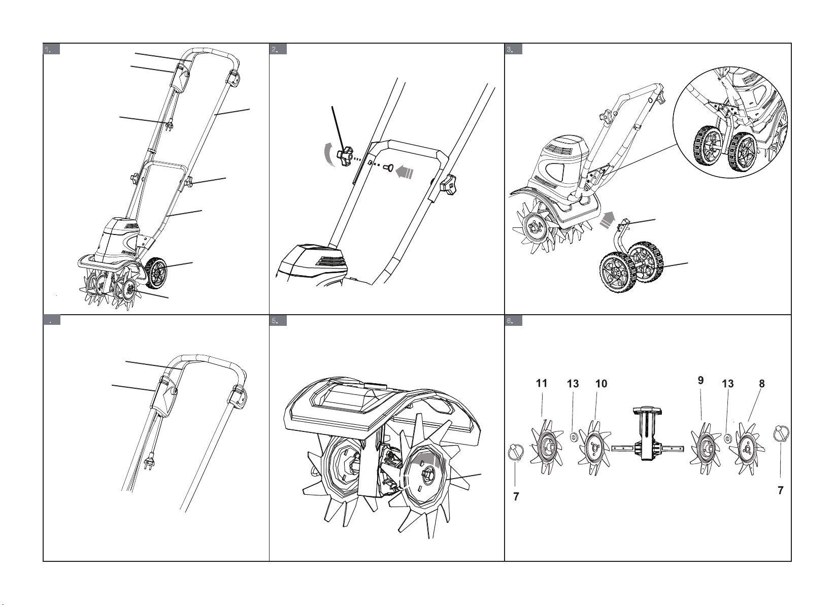
6. Den äußeren Hackstern A auf die rechte Seite der
Hacksternwelle legen. Die Seite mit der Prägung sollte in
Richtung Hackstern B zeigen.
7. Um die Hacksterne an der Hacksternwelle zu befestigen,
stecken Sie die Ringstifte in die Löcher auf beiden Seiten
der Hacksternwelle.
HINWEIS
Bei falscher Montage der Hacksterne funktioniert das Gerät
nicht einwandfrei. Wenn Sie ein Problem mit dem
Kultivierungsbetrieb des Gerätes feststellen, überprüfen Sie
die korrekte Positionierung der Hacksterne.
WARNUNG
Die Hacksterne und die Maschine können beschädigt
werden, auch wenn Sie die Maschine bei ausgeschaltetem
Motor bewegen. Um zu verhindern, dass die Hacksterne
während der Fahrt den Boden berühren, kippen Sie die
Maschine bitte.
4 ANWENDUNGEN
• Auflockern von Gartenerde zur Vorbereitung des
Saatbeetes für die Pflanzung.
• Flache Bodenbearbeitung, um Unkraut zu entfernen.
4.1 MASCHINE STARTEN
Abbildung 4.
1. Schließen Sie die Maschine an ein für den Außenbereich
zugelassenes Verlängerungskabel an.
2. Drücken und halten Sie die Sicherheitssperrtaste.
3. Ziehen Sie den Bügelschalter in Richtung Griff, während
Sie die Taste für die Sicherheitssperrtaste gedrückt halten.
4. Lassen Sie die Sicherheitssperrtaste los.
WARNUNG
Halten Sie die Maschine im laufenden Betrieb mit beiden
Händen fest.
HINWEIS
Stellen Sie sich hinter die Maschine, mit den Hacksternen
auf dem Boden und dem Arbeitsbereich sauber und frei von
Hindernissen.
4.2 MASCHINE ANHALTEN
Abbildung 4.
1. Den Bügelschalter loslassen, um die Maschine
anzuhalten.
4.3 SCHMALE
BEARBEITUNGSBREITE
Die beiden äußeren Hacksterne können entfernt werden, um
eine schmalere Bearbeitungsbreite zu ermöglichen.
1. Entfernen Sie die Ringstifte aus den Bohrungen an den
Enden der Hacksternwelle.
2. Entfernen Sie die äußeren Hacksterne und Filze von der
Hacksternwelle.
3. Setzen Sie die Anhängestifte in die Löcher ein.
4.4 TIPPS ZUR BEDIENUNG
Mit dem Kultivator können Sie Gartenerde auflockern und
ein Saatbeet für die Pflanzung vorbereiten. Denken Sie daran,
genügend Platz zwischen den Saatreihen zu lassen, damit eine
maschinelle Bearbeitung nach dem Wachstum der Pflanzen
möglich ist.
1. Es können mehrere Durchläufe über dieselbe Bahn
erforderlich sein, um die gewünschte Tiefe zu erreichen.
Versuchen Sie nicht, im ersten Durchgang zu tief zu
graben.
2. Wenn die Maschine springt oder bockt, lassen Sie die
Einheit etwas schneller vorwärts fahren oder installieren
Sie den Radsatz.
3. Wenn der Kultivator an einer Stelle bleibt und sich
eingräbt, versuchen Sie, ihn durch seitliches Hin- und
Herschaukeln wieder in Bewegung zu setzen.
4. Wenn der Boden sehr hart ist, gießen Sie ihn einige Tage
vor der Bearbeitung. Vermeiden Sie es, den Boden bei
Nässe oder Feuchtigkeit zu bearbeiten. Warten Sie ein
oder zwei Tage nach starkem Regen, bis der Boden
trocken ist.
5. Flache Bodenbearbeitung mit einer Tiefe von weniger als
5 cm kann dazu eingesetzt werden, um Unkraut zu
zerstören und den Boden zu belüften, ohne die
nahegelegenen Pflanzenwurzeln zu verletzen. Dies sollte
häufig durchgeführt werden, damit das Unkraut nicht zu
groß wird und sich in den Hacksternen des Gerätes
verfängt.
5 WARTUNG UND
INSTANDHALTUNG
VORSICHT
Lassen Sie Bremsflüssigkeiten, Benzin und
mineralölbasierte Materialien nicht mit den Kunststoffteilen
in Berührung kommen. Chemikalien können den Kunststoff
beschädigen und ihn unbrauchbar machen.
VORSICHT
Verwenden Sie keine starken Lösungsmittel oder
Reinigungsmittel auf dem Kunststoffgehäuse oder den
Bauteilen.
WARNUNG
Nehmen Sie den Akkupack vor der Wartung aus der
Maschine.
10
Deutsch
DE

5.1 MASCHINE REINIGEN
WARNUNG
Halten Sie die Maschine und den Motor frei von Blättern,
Zweigen oder überschüssigem Öl, um Feuergefahren zu
vermeiden.
• Verwenden Sie ein feuchtes Tuch, um die Maschine zu
reinigen.
• Entfernen Sie alle Feuchtigkeit mit einem trockenen
Tuch.
• Verwenden Sie einen kleinen Pinsel, um die
Belüftungslöcher zu reinigen.
6 MASCHINE LAGERN
• Reinigen Sie die Maschine vor der Lagerung.
• Stellen Sie sicher, dass der Motor nicht heiß ist, wenn Sie
die Maschine verstauen.
• Stellen Sie sicher, dass die Maschine keine losen oder
beschädigten Teile aufweist. Wenn es notwendig ist,
führen Sie diese Schritte/Anweisungen aus:
• Tauschen Sie die beschädigten Teile aus.
• Ziehen Sie die Schrauben an.
• Sprechen Sie mit einem Mitarbeiter eines
zugelassenen Servicezentrums.
• Verstauen Sie die Maschine an einem trockenen Ort.
• Stellen Sie sicher, dass Kinder nicht in die Nähe der
Maschine kommen können.
7 FEHLERBEHEBUNG
Problem Mögliche Urs-
ache
Lösung
Der Motor startet
nicht, wenn der
Bügelschalter ge-
drückt wird.
Das Netzkabel ist
nicht eingesteckt
oder die Verbin-
dung locker.
Schließen Sie das
Netzkabel an.
Der Schutzschalter
wird ausgelöst.
Prüfen Sie den
Schutzschalter.
Die Maschine
raucht im Betrieb.
Die Maschine ist
beschädigt.
1. Stoppen Sie
die Maschine
sofort.
2. Ziehen Sie den
Netzstecker.
3. Sprechen Sie
mit dem Serv-
icecenter.
Problem Mögliche Urs-
ache
Lösung
Der Motor läuft,
aber die Hack-
sterne bewegen
sich nicht.
Die Maschine ist
beschädigt.
Verwenden Sie die
Maschine nicht
mehr und sprechen
Sie mit dem Serv-
icecenter.
Die Hacksterne
sind blockiert.
Trennen Sie die
Maschine und en-
tfernen Sie dann
die Verstopfung in
den Hacksternen.
Getriebeausfall. Sprechen Sie mit
dem Servicecenter.
8 TECHNISCHE DATEN
Leistung 950W
Leerlaufdrehzahl 320 (±10%) /min
Kultivierungsbahn 10'' (26 cm)
Schutzgrad IPX4
Gewicht 12.1 kg
Gemessener Schalldruckpegel LPA= 78.5 dB(A) ,
KPA= 3 dB(A)
Garantierter Schallleistungspegel LWA.d= 93 dB(A)
Vibration 3.2 m/s2
Messunsicherheit K = 1.5 m/s2
9 GARANTIE
(Die vollständigen Garantiebedingungen finden Sie auf der
Website von Greenworks)
Die Greenworks-Garantie beträgt 3 Jahre auf das Produkt und
2 Jahre auf die Akkus (Käufer/Privatgebrauch) ab
Kaufdatum. Diese Garantie deckt Herstellungsfehler ab. Ein
im Rahmen der Garantie fehlerhaftes Produkt kann entweder
repariert oder ersetzt werden. Ein Gerät, das missbräuchlich
oder auf andere Weise als zu in der Bedienungsanleitung
beschrieben Zwecken verwendet wurde, kann von der
Garantie ausgeschlossen werden. Normaler Verschleiß und
Verschleißteile sind von der Garantie ausgeschlossen. Die
ursprüngliche Herstellergarantie wird durch eine zusätzliche
Garantie eines Händlers oder Einzelhändlers nicht
beeinträchtigt.
Ein fehlerhaftes Produkt muss zusammen mit dem
Kaufnachweis (Quittung) an die Verkaufsstelle
zurückgeschickt werden, um Garantieansprüche geltend zu
machen.
11
Deutsch
DE

10 EG-
KONFORMITÄTSERKLÄRUNG
Name und Anschrift des Herstellers:
Name: GLOBGRO AB
Globe Group Europe
Adresse: Riggaregatan 53, 211 13 Malmö, Sweden
Name und Anschrift der Person, die zur Erstellung der
technischen Unterlagen berechtigt ist:
Name: Peter Söderström
Adresse: Riggaregatan 53, 211 13 Malmö, Sweden
Hiermit erklären wir, dass das Produkt
Kategorie: Kultivator
Modell: 27017(CUA101)
Seriennummer: Siehe Produktetikett
Baujahr: Siehe Produktetikett
• den einschlägigen Bestimmungen der Maschinenrichtlinie
2006/42/EG entspricht.
• mit den Bestimmungen der folgenden anderen
EGRichtlinien übereinstimmt:
• 2014/30/EU
• 2000/14/EG & 2005/88/EG
• 2011/65/EU & (EU)2015/863
Darüber hinaus erklären wir, dass die folgenden Teile,
Klauseln von harmonisierten Normen verwendet wurden.
• EN55014-1; EN55014-2; EN61000-3-2;
EN61000-3-3;EN 62233; EN60335-1; EN709
Angewandtes Konformitätsbewertungsverfahren gemäß
Richtlinie 2000/14/EG Anhang VI.
Gemessener Schallleistungspegel LWA: 91.6 dB(A)
Garantierter Schallleistungspegel LWA.d: 93 dB(A)
Ort, Datum: Malmö,
12.12.2019
Unterschrift: Ted Qu, Qualitätsleiter
12
Deutsch
DE

1 Descripción.......................................14
1.1 Uso previsto.....................................................14
1.2 Perspectiva general..........................................14
2 Seguridad......................................... 14
3 Instalación........................................14
3.1 Desembalaje de la máquina............................. 14
4 Aplicaciones..................................... 15
4.1 Puesta en marcha de la máquina......................15
4.2 Detención de la máquina................................. 15
4.3 Anchura de cultivo estrecha............................ 15
4.4 Consejos de funcionamiento............................15
5 Mantenimiento.................................15
5.1 Limpieza de la máquina...................................15
6 Almacenamiento de la máquina.....16
7 Solución de problemas.................... 16
8 Datos técnicos.................................. 16
9 Garantía........................................... 16
10 Declaración de conformidad CE....16
13
Español
ES

1 DESCRIPCIÓN
1.1 USO PREVISTO
El cultivador a batería se ha diseñado para aflojar la tierra en
una zona ajardinada abierta. Este producto no está destinado
para un uso comercial.
1.2 PERSPECTIVA GENERAL
Figura 1-6
1Asa superior
2Asa inferior
3Tuerca de mariposa
4Interruptor de
seguridad
5Botón de bloqueo de
seguridad
6Conjunto de las
ruedas
7Pasador de anillo
8Diente A
9Diente B
10 Diente C
11 Diente D
12 Pasador de enganche
13 Fieltro
14 Conector de enchufe
2 SEGURIDAD
AVISO
Asegúrese de seguir/respetar todas las instrucciones de
seguridad.
Consulte el manual de seguridad.
3 INSTALACIÓN
AVISO
No cambie ni utilice accesorios que no sean los
recomendados por el fabricante.
AVISO
No conecte la máquina a la fuente de alimentación hasta
que haya montado todas las piezas.
3.1 DESEMBALAJE DE LA MÁQUINA
AVISO
Asegúrese de montar correctamente la máquina antes del
uso.
AVISO
• Si las piezas presentan daños, no utilice la máquina.
• Si no tiene todas las piezas, no utilice la máquina.
• Si faltan piezas o hay piezas dañadas, hable con el
centro de servicio.
1. Abra el embalaje.
2. Lea la documentación que se encuentra en la caja.
3. Retire todas las piezas sin montar de la caja.
4. Retire la máquina de la caja.
5. Deseche la caja y el embalaje de conformidad con los
reglamentos locales.
3.1.1 INSTALACIÓN DEL ASA
Figura 2.
1. Alinee los orificios del asa superior con los orificios del
asa inferior.
2. Introduzca los pernos por las asas.
3. Utilice las tuercas de mariposa para apretarlos.
3.1.2 INSTALACIÓN DE LA RUEDA
Figura 3.
1. Inserte el conjunto de las ruedas en la barra de soporte.
2. Alinee el orificio del conjunto de las ruedas en la posición
deseada.
3. Deslice el perno por el orificio y fije el pasador de
enganche al perno.
NOTA
La posición de las ruedas de la máquina es ajustable. Puede
controlar la profundidad de funcionamiento mediante el
ajuste de la posición de las ruedas.
NOTA
Las ruedas pueden quitarse para una profundidad de labrado
mayor.
3.1.3 INSTALACIÓN DE LOS DIENTES
Figura 6.
El cultivador tiene cuatro dientes - dos dientes interiores
estampados B y C y dos dientes exteriores estampados A y D.
Para el correcto funcionamiento de la unidad, los dientes
deben instalarse en la orientación correcta.
1. Coloque la máquina sobre una superficie plana y lisa.
2. Coloque el diente C en el eje de los dientes a la izquierda
de la caja de engranajes. El lado estampado del diente
debe quedar alejado de la caja de engranajes.
3. Coloque el diente B en el eje de los dientes a la derecha
de la caja de engranajes. El lado estampado del diente
debe quedar alejado de la caja de engranajes.
4. Coloque una arandela de fieltro a cada lado del eje de los
dientes y deslice para apoyarla contra los dientes
interiores.
5. Coloque el diente exterior D en el lado izquierdo del eje
de los dientes. El lado estampado debe mirar hacia el
diente C.
6. Coloque el diente exterior A en el lado derecho del eje de
los dientes. El lado estampado debe mirar hacia el diente
B.
14
Español
ES

7. Para fijar los dientes al eje de los dientes, inserte los
pasadores de anillo en los orificios situados a ambos
lados del eje de los dientes.
NOTA
La unidad no funcionará correctamente si los dientes están
instalados incorrectamente. Si observa un problema con la
operación de cultivo de la unidad, compruebe la colocación
correcta de los dientes.
AVISO
Los dientes y la máquina pueden sufrir daños incluso si
mueve la máquina con el motor apagado. Para evitar que los
dientes toquen el suelo durante el movimiento, incline la
máquina.
4 APLICACIONES
• Disgregado de la tierra del jardín para preparar semilleros
para la plantación.
• Cultivo superficial para eliminar las malas hierbas.
4.1 PUESTA EN MARCHA DE LA
MÁQUINA
Figura 4.
1. Conecte la máquina a un cable alargador aprobado para
exterior.
2. Pulse y mantenga pulsado el botón de bloqueo de
seguridad.
3. Mientras mantiene pulsado el botón de bloqueo de
seguridad, tire del interruptor de seguridad hacia el asa.
4. Suelte el botón de bloqueo de seguridad.
AVISO
Sujete la máquina con las dos manos durante el
funcionamiento.
NOTA
Colóquese detrás de la máquina con los dientes en el suelo y
la superficie de trabajo limpia y sin obstrucciones.
4.2 DETENCIÓN DE LA MÁQUINA
Figura 4.
1. Suelte el interruptor de seguridad para detener la
máquina.
4.3 ANCHURA DE CULTIVO
ESTRECHA
Las dos cuchillas de dientes exteriores pueden retirarse de la
unidad para permitir una anchura de cultivo más estrecha.
1. Retire los pasadores de anillo de los orificios en los
extremos del eje de los dientes.
2. Retire los dientes exteriores y los fieltros del eje de los
dientes.
3. Coloque los pasadores de enganche en los orificios.
4.4 CONSEJOS DE
FUNCIONAMIENTO
El cultivador puede utilizarse para disgregar la tierra del
jardín y preparar un semillero para plantar. Planifique con
antelación para dejar suficiente espacio entre las hileras de
semillas para permitir el cultivo a máquina después de que las
plantas hayan crecido.
1. Puede que sea necesario pasar varias veces sobre el
mismo surco para alcanzar la profundidad deseada. No
intente cavar demasiado profundo en la primera pasada.
2. Si la máquina salta o gira, deje que la unidad avance a
una velocidad ligeramente más rápida o instale el
conjunto de las ruedas.
3. Si el cultivador se queda y cava en un lugar, intente
moverlo de lado a lado para que empiece a avanzar
nuevamente.
4. Si la tierra está muy compactada, riegue unos días antes
de cultivar. Evite trabajar la tierra cuando esté húmeda o
mojada. Espere uno o dos días después de fuertes lluvias
para que la tierra se seque.
5. El cultivo superficial de menos de 5 cm. puede utilizarse
para quitar las malas hierbas y airear la tierra, sin dañar
las raíces de las plantas cercanas. Debe hacerse con
frecuencia para que no crezcan las malas hierbas y
produzcan enredos en los dientes de la unidad.
5 MANTENIMIENTO
PRECAUCIÓN
No permita que líquidos de frenos, gasolina y otros
derivados del petróleo toquen las piezas de plástico. Las
sustancias químicas pueden dañar el plástico y hacer que
quede inservible.
PRECAUCIÓN
No utilice disolventes o detergentes fuertes en la carcasa o
los componentes de plástico.
AVISO
Retire la batería de la máquina antes de realizar tareas de
mantenimiento.
5.1 LIMPIEZA DE LA MÁQUINA
AVISO
Mantenga la máquina y el motor libres de hojas, ramas o
exceso de aceite para evitar riesgos de incendio.
• Utilice un paño húmedo con un detergente suave para
limpiar la máquina.
15
Español
ES

• Limpie toda la humedad con un paño suave y seco.
• Utilice un cepillo pequeño para limpiar los orificios de
ventilación.
6 ALMACENAMIENTO DE LA
MÁQUINA
• Limpie la máquina antes del almacenamiento.
• Asegúrese de que el motor no esté caliente cuando
almacene la máquina.
• Asegúrese de que la máquina no tenga piezas sueltas o
dañadas. Si es necesario, siga estos pasos/estas
instrucciones:
• Sustituya las piezas dañadas.
• Apriete los pernos.
• Hable con una persona de un centro de servicio
aprobado.
• Almacene la máquina en una zona seca.
• Asegúrese de que los niños no puedan acercarse a la
máquina.
7 SOLUCIÓN DE PROBLEMAS
Problema Posible causa Solución
El motor no consi-
gue arrancar cuan-
do está presionado
el interruptor de
seguridad.
El cable de ali-
mentación no está
enchufado o la
conexión está su-
elta.
Enchufe el cable
de alimentación.
El disyuntor del
circuito doméstico
ha saltado.
Compruebe el di-
syuntor del circui-
to.
La máquina echa
humo durante el
funcionamiento.
La máquina ha su-
frido daños.
1. Detenga la
máquina inme-
diatamente.
2. Desenchufe la
máquina.
3. Consulte con
un centro de
servicio.
El motor funciona
pero los dientes no
se mueven.
La máquina ha su-
frido daños.
No utilice la má-
quina y consulte
con un centro de
servicio.
Los dientes están
bloqueados.
Desenchufe la má-
quina, posterior-
mente elimine el
bloqueo de los di-
entes.
Fallo del tren de
engranajes.
Consulte con un
centro de servicio.
8 DATOS TÉCNICOS
Potencia 950W
Velocidad sin carga 320 (±10%) /min
Surco de cultivo 10'' (26 cm)
Grado de protección IPX4
Peso 12.1 kg
Nivel de presión acústica medida LPA= 78.5 dB(A) ,
KPA= 3 dB(A)
Nivel de potencia acústica garantizada LWA.d= 93 dB(A)
Vibración 3.2 m/s2
Incertidumbre K = 1.5 m/s2
9 GARANTÍA
(La totalidad de las condiciones de la garantía puede
encontrarse en la página web de Greenworks)
La garantía de Greenworks es de 3 años para el producto y 2
años para las baterías (uso privado / del consumidor) a partir
de la fecha de compra. Esta garantía cubre defectos de
fabricación. Un producto defectuoso en garantía puede ser
reparado o sustituido. Una unidad que haya sido mal utilizada
o utilizada de modo distinto al que se describe en el manual
del propietario puede no tener derecho a garantía. El desgaste
normal y las piezas de desgaste no están cubiertos por la
garantía. La garantía original del fabricante no se ve afectada
por ninguna garantía adicional ofrecida por un distribuidor o
minorista.
Un producto defectuoso debe devolverse al punto de compra
para reclamar la garantía, junto con el comprobante de
compra (ticket).
10 DECLARACIÓN DE
CONFORMIDAD CE
Nombre y dirección del fabricante:
Nombre: GLOBGRO AB
Globe Group Europe
Dirección: Riggaregatan 53, 211 13 Malmö, Suecia
Nombre y dirección de la persona autorizada para compilar el
archivo técnico:
Nombre: Peter Söderström
Dirección: Riggaregatan 53, 211 13 Malmö, Suecia
Por la presente declaramos que el producto
Categoría: Cultivador
Modelo: 27017(CUA101)
16
Español
ES

Número de serie: Véase la etiqueta de clasificación
del producto
Año de construcción: Véase la etiqueta de clasificación
del producto
• es conforme con las disposiciones pertinentes de la
Directiva relativa a las máquinas (2006/42/CE).
• es conforme con las disposiciones de las siguientes
Directivas CE:
• 2014/30/UE
• 2000/14/CE y 2005/88/CE
• 2011/65/UE y 2015/863/UE
Adicionalmente, declaramos que se han utilizado las
siguientes partes o cláusulas de las normas armonizadas:
• EN55014-1; EN55014-2; EN61000-3-2;
EN61000-3-3;EN 62233; EN60335-1; EN709
Método de evaluación de conformidad según el anexo VI /
Directiva 2000/14/CE.
Nivel de potencia acústica medida LWA: 91.6 dB(A)
Nivel de potencia acústica garanti-
zada
LWA.d: 93 dB(A)
Lugar, fecha: Malmö,
12.12.2019
Firma: Ted Qu, Director de calidad
17
Español
ES

1 Descrizione.......................................19
1.1 Destinazione d'uso........................................... 19
1.2 Panoramica...................................................... 19
2 Sicurezza.......................................... 19
3 Installazione.....................................19
3.1 Disimballaggio dell'apparecchio......................19
4 Destinazione d'uso...........................20
4.1 Avvio dell'apparecchio.................................... 20
4.2 Arresto dell'apparecchio.................................. 20
4.3 Riduzione dell'ampiezza di coltivazione......... 20
4.4 Suggerimenti per l'uso..................................... 20
5 Manutenzione.................................. 20
5.1 Pulizia dell'apparecchio................................... 20
6 Conservazione dell'apparecchio.....21
7 Risoluzione dei problemi................ 21
8 Specifiche tecniche...........................21
9 Garanzia...........................................21
10 Dichiarazione di conformità CE.... 21
18
Italiano
IT

1 DESCRIZIONE
1.1 DESTINAZIONE D'USO
Questo coltivatore a batteria è destinato a smuovere il terreno
in aree verdi aperte. Questo prodotto non è destinato all'uso
commerciale.
1.2 PANORAMICA
Figura 1-6
1Manubrio superiore
2Manubrio inferiore
3Dado a farfalla
4Barra di avanzamento
5Pulsante di
bloccaggio
6Gruppo ruota
7Perno ad anello
8Rebbio A
9Rebbio B
10 Rebbio C
11 Rebbio D
12 Perno di attacco
13 Rondella in feltro
14 Connettore spina
2 SICUREZZA
AVVERTIMENTO
Rispettare e applicare tutte le avvertenze di sicurezza.
Fare riferimento alle avvertenze di sicurezza.
3 INSTALLAZIONE
AVVERTIMENTO
Non modificare o installare accessori non raccomandati dal
costruttore.
AVVERTIMENTO
Non collegare l'apparecchio alla rete elettrica finché tutte le
parti non sono state assemblate.
3.1 DISIMBALLAGGIO
DELL'APPARECCHIO
AVVERTIMENTO
Assicurarsi di assemblare correttamente l'apparecchio prima
dell'uso.
AVVERTIMENTO
• Se uno o più componenti sono danneggiati, non usare
l'apparecchio.
• Se uno o più componenti sono mancanti, non usare
l'apparecchio.
• In caso di componenti danneggiati o mancanti,
contattare il centro di assistenza.
1. Aprire l'imballaggio.
2. Leggere i documenti contenuti nell'imballaggio.
3. Estrarre gli accessori dall'imballaggio.
4. Estrarre l'apparecchio dall'imballaggio.
5. Smaltire l'imballaggio conformemente alle normative
locali.
3.1.1 INSTALLAZIONE DEL MANUBRIO
Figura 2.
1. Allineare i fori del manubrio superiore con i fori del
manubrio inferiore.
2. Inserire i bulloni attraverso i manubri.
3. Usare i dadi a farfalla per serrarli.
3.1.2 INSTALLAZIONE DELLA RUOTA
Figura 3.
1. Inserire il gruppo ruota nell'asta di supporto.
2. Allineare il foro del gruppo ruota con la posizione
desiderata.
3. Infilare il bullone attraverso il foro e fissare il perso di
attacco al bullone.
NOTA
La posizione della ruota è regolabile. È possibile controllare
la profondità dell'operazione regolando la posizione della
ruota.
NOTA
Le ruote possono essere rimosse per aumentare
ulteriormente la profondità di dissodamento.
3.1.3 INSTALLAZIONE DEI REBBI
Figura 6.
Il coltivatore è dotato di quattro rebbi: i due rebbi interni B e
C e i due rebbi esterni A e D. Per il funzionamento corretto
dell'apparecchio, i rebbi devono essere installati
nell'orientamento corretto.
1. Posizionare l'apparecchio su una superficie piana e liscia.
2. Posizionare il rebbio C sull'asse a sinistra della scatola
ingranaggi. Il lato stampato del rebbio deve essere rivolto
dal lato opposto della scatola ingranaggi.
3. Posizionare il rebbio B sull'asse a destra della scatola
ingranaggi. Il lato stampato del rebbio deve essere rivolto
dal lato opposto della scatola ingranaggi.
4. Posizionare una rondella in feltro su ciascun lato dell'asse
e spingerla contro i rebbi interni.
5. Posizionare il rebbio esterno D sul lato sinistro dell'asse.
Il lato stampato deve essere rivolto verso il rebbio C.
6. Posizionare il rebbio esterno A sul lato destro dell'asse. Il
lato stampato deve essere rivolto verso il rebbio B.
7. Per fissare i rebbi sull'asse, inserire i perni ad anello nei
fori situati su ciascun lato dell'asse.
19
Italiano
IT

NOTA
L'apparecchio non funzionerà correttamente se i rebbi sono
installati in modo errato. In caso di malfunzionamento
dell'operazione di coltivazione dell'apparecchio, assicurarsi
che i rebbi siano posizionati correttamente.
AVVERTIMENTO
I rebbi e l'apparecchio possono subire danni anche
spostando l'apparecchio a motore spento. Per evitare che i
rebbi tocchino il terreno durante lo spostamento, inclinare
l'apparecchio.
4 DESTINAZIONE D'USO
• Dissodare il terreno per preparare il letto di semina.
• Coltivare il terreno in superficie per rimuovere le erbacce.
4.1 AVVIO DELL'APPARECCHIO
Figura 4.
1. Collegare l’apparecchio a un cavo prolunga da esterno
approvato.
2. Premere e tenere premuto il pulsante di sicurezza.
3. Tirare la barra di avanzamento verso il manubrio tenendo
premuto il pulsante di bloccaggio.
4. Rilasciare il pulsante di sicurezza.
AVVERTIMENTO
Impugnare l'apparecchio con entrambe le mani durante
l'uso.
NOTA
Posizionarsi dietro l'apparecchio con i rebbi sul terreno e
l'area di lavoro sgombra e priva di ostacoli.
4.2 ARRESTO DELL'APPARECCHIO
Figura 4.
1. Rilasciare la barra di avanzamento per arrestare
l'apparecchio.
4.3 RIDUZIONE DELL'AMPIEZZA DI
COLTIVAZIONE
I due rebbi esterni possono essere rimossi per ridurre
l'ampiezza di coltivazione.
1. Rimuovere i perni ad anello dai fori sulle estremità
dell'asse.
2. Rimuovere i rebbi esterni e le rondelle in feltro dall'asse.
3. Posizionare i perni di attacco nei fori.
4.4 SUGGERIMENTI PER L'USO
Il coltivatore può essere usato per dissodare il terreno e
preparare il letto di semina. Pianificare l'operazione in modo
tale da lasciare abbastanza spazio tra le file di semi e
permettere la coltivazione dopo la crescita delle piante.
1. Potrebbe essere necessario effettuare diverse passate sullo
stesso percorso per raggiungere la profondità desiderata.
Non scavare troppo a fondo durante la prima passata.
2. Se l'apparecchio salta o fuoriesce, lasciare che
l'apparecchio avanzi a una velocità leggermente maggiore
o installare il gruppo ruota.
3. Se il coltivatore si incastra in un punto, farlo dondolare da
un alto all'altro affinché riprenda ad avanzare.
4. Se il terreno è molto duro, annaffiarlo per qualche giorno
prima di usare l'apparecchio. Non usare l'apparecchio se il
terreno è inzuppato o bagnato. Dopo un'intensa pioggia,
attendere un giorno o due affinché il terreno si asciughi.
5. Una coltivazione superficiale, inferiore a 5 cm di
profondità, è ideale per eliminare le erbacce e areare del
terreno, senza danneggiare le radici delle piante vicine.
Effettuare frequentemente tale operazione per evitare la
crescita di erbacce che potrebbero impigliarsi nei rebbi
dell'apparecchio.
5 MANUTENZIONE
AVVERTENZA
Evitare che le parti in plastica entrino a contatto con olio dei
freni, benzina e materiali a base di petrolio. Gli agenti
chimici possono danneggiare la plastica e renderla
inservibile.
AVVERTENZA
Non usare detergenti o solventi aggressivi sulle parti in
plastica.
AVVERTIMENTO
Rimuovere il gruppo batteria dall'apparecchio prima di
sottoporlo a manutenzione.
5.1 PULIZIA DELL'APPARECCHIO
AVVERTIMENTO
Mantenere l'apparecchio e il motore privi di foglie, rami o
olio per evitare il rischio di incendio.
• Usare un panno umido e del detergente delicato per pulire
l'apparecchio.
• Rimuovere eventuali tracce di umidità con un panno
morbido e asciutto.
• Usare una piccola spazzola per pulire le aperture di
ventilazione.
20
Italiano
IT
This manual suits for next models
1
Table of contents
Languages:
Other GreenWorks Tiller manuals

GreenWorks
GreenWorks 27072 User manual

GreenWorks
GreenWorks 27062 User manual

GreenWorks
GreenWorks Pro TL60L00 User manual

GreenWorks
GreenWorks 27062 User manual

GreenWorks
GreenWorks 2800100 User manual

GreenWorks
GreenWorks CUA108 User manual

GreenWorks
GreenWorks 27017 User manual

GreenWorks
GreenWorks 27062A User manual

GreenWorks
GreenWorks G40TL User manual

GreenWorks
GreenWorks CUA91 User manual