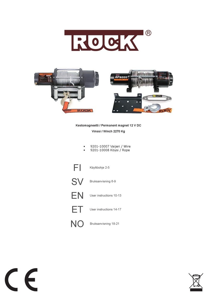
ROCK RP2000 Series User manual

ELECTRIC WINCH
Model RP2000/RP3500/RP5000/RES4000 series
IATF
TO PREVENT SERIOUS INJURY,
READ AND UNDERSTAND ALL WARNINGS
AND INSTRUCTIONS BEFORE USE.
16949 : 2016 ISO 9001:2015
Due to continuing improvements,
actual product may differ slightly from the product described herein.

INDEX
Safey Warning & Precautions -------------------------------------------------------
--------------
Page 1
Installation Instructions ----------------------------------------------------------------
--------------
Page 1
Installation Instructions-Wiring ------------------------------------------------------
--------------
Page 2
Installation Instructions-Wiring-continue ------------------------------------------
--------------
Page 3
Clutch Operation ------------------------------------------------------------------------
--------------
Page 4
Winch Operation ------------------------------------------------------------------------
--------------
Page 4
Winch Operation-continue ------------------------------------------------------------
-------------
Page 5
Wireless Remote Control Operation -----------------------------------------------
--------------
Page 5
Maintenance & Service ---------------------------------------------------------------
--------------
Page 6
Trouble Shooting -----------------------------------------------------------------------
--------------
Page 6
Specifications-RP2000 & REW2000 -----------------------------------------------
-------------
Page 7
Specifications-RP3500 ----------------------------------------------------------------
--------------
Page 8
Specifications-RP5000 ----------------------------------------------------------------
--------------
Page 9
Specifications-RES4000 --------------------------------------------------------------
--------------
Page10
Winch Assembly Drawing & Parts List-RP2000,REW2000 ------------------
--------------
Page11
Winch Assembly Drawing-RP3500,RP5000 -------------------------------------
--------------
Page12
Winch Parts List-RP3500,RP5000 -------------------------------------------------
--------------
Page13
Winch Assembly Drawing & Parts List-RES4000 ------------------------------
--------------
Page14

SAFETY WARNING & PRECAUTIONS
Page 1
Read the entire technical and safety information in this manual before set up or use of this
winch. Observe safety precautions for personal safety and the safety of others. The
instructions that follow are basic guidelines only and can not cover all situations
encountered during use. The operator and assistants must carefully plan usage to prevent
accidents.
1. Do not operate winch under influence of drugs or alcohol.
2. Read manual before using this winch.
3. Always use heavy gloves when handling wire rope.
4. Never hook the cable back upon itself. The cable can break under tension and cause injury and
damage.
5. Stay clear of wire rope and keep others away when in operation or with load on wire.
6. Inspect winch and wire rope before each use. Do not use winch if wire rope or winch shows wear or
damage.
7. Replace any parts as needed before using the winch.
8. Do not exceed the winch capacity.
9. Do not use the winch as a hoist or to move people.
10. Do not use winch to secure a load or tow vehicles.
11. This winch is designed for intermittent use only.
12. Look to see where the frill bit will come through before drilling holes for installation.
13. Never drill into the gas tank or electrical wiring.
14. Place towel or sandbag over wire while winch is in use. Fig.1
15. Keep hands clear of wire rope, hook and fairlead opening during operation. Fig.2
Always use handsaving belt to hold hook when spooling.Fig.3
Fig.1Fig.2Fig.3
INSTALLATION INSTRUCTIONS
When installing a winch, your installation may vary from the manual diagrams and
instructions included here due to vehicle and mounting operation in the structure. Always
disconnect the battery from the vehicle to remove the electric hazard.
CAUTION:
If you choose not to use an ATV mounting kit, You may be required to drill holes in a structural
support on the ATV. Be sure the location will be strong enough to support the rated pulling force of the
winch. Do not drill into wiring or gas tank! If the mounting bolts needed are different in length from that
supplied, use a bolt of equal or better quality to that supplied by the manufacturer. Tight the mounting
bolts to required torque.
1. Install the mounting kits or prepare a flat and secure location on the vehicle for the winch.
2. Position teh winch over the mount and check for operation of the clutch lever to frame clearance.
Check for tire to winch clearance. If ok, continue on to the next step.
3. Secure the winch to the mounting bracket or surface chosen with the correct hardware.
NOTE:
Make sure the winch mounting bolts and winch hardware have been checked for proper torque.

INSTALLATION INSTRUCTIONS-WIRING
Page 2
1). Plan a route for the wiring from the point of the vehicle where the winch will be mounted, or
used, to the battery. This route must be secure, out of the way of moving parts, road debris, or any
possibility of being damaged by operation or maintenance of the vehicle. For example, you may
wish to route the wires under the vehicle, attaching it to the frame using suitable fasteners. Do not
attache the wires to the exhaust system, drive shaft, emergency brake cable, fuel line, or any other
components which may create damage the wiring through heat or motion, or create a fire hazard.
2). If you drill through the bumper or any part of the body to route the wires, be sure to install a
rubber grommet in the hole to prevent fraying of the wires at that point.
3). Route the Cables from the Solenoid to the battery and from the Solenoid to the Winch,
following the precautions discussed earlier.
4). Attach the wires from the Solenoid to the terminals on the Winch.
5). Attache the Circuit Breaker(supplied to special order) to the positive terminal on the battery.
6). Attach the red Battery Cable to the Circuit Breaker.
7). Attach the black Battery Cable directly to the negative terminal of the battery.
1. For RP2000 & REW2000
Fig. 4
2) Option 2- switch control (see Fig.5)
1). Connect 2 short cables to motor terminals.Red cable to motor terminal marked in red. Black
cable to motor terminal marked in black.
2). Connect 2 long cables to 2 battery terminals. Red cable to battery positive terminal. Black
cable to battery negative terminal.
1) Option 1- solenoid and wireless remote control (see Fig.4)
RP2000 REW2000(stainless steel)
Fig.5
BATTERY
CONTROL BOX
winch motor
Circuit Breaker
(optional)
Wireless Remote
Controller
+
_
+
_
Red
Red Black
Black
Black
Red
Black
Red
BATTERY
+
-
+-

INSTALLATION INSTRUCTIONS-WIRING-continue
Page 3
RedRedRedRed
RedRedRedRed
BlackBlackBlackBlack
BrownBrownBrownBrown
RedRedRedRed
(to(to(to(toignion)
BlueBlueBlueBlue
BlueBlueBlueBlue
WinchWinchWinchWinch
BlackBlackBlackBlack RedRedRedRed
Remote
Wireless remote
control
Solenoid
Yellow
Blue
Baery
Handlebar
remote
Master switch
2. For RP3500,RP5000 & RES4000
RP2000 RP5000 REW4000
1) Plan a rout for the wiring from the point
of the vehicle where winch will be
mounted,or used to the battery. This
route must be secure, out of the way
of moving parts, road devris,or any
possibility of being damaged by
operation of the vehicle.Fig.6
2) Route the cables from the solenoid to
the battery and from solenoid to winch.
Follow the precautions discussed above.
3) Attach the wires from the solenoid
to the terminals on the winch.
4) Attach the Master Switch(or Circuit
Breaker) to the positive terminal on
battery-optional.
5) Attach the red battery cable to Master
Switch(or Circuit Breaker)-optional.
6) Attach the black battery cable directly to the
negative terminal of the battery.
7) Wire in the switch controller.
8) The cable leading from the switch controller has a red wire extending
out from its side. Connect this to an ignition circuit(switched by the
vehicle’s key) to help prevent accidental starting. The winch will not
operate if that wire is not properly connected.
optional
(Circuit Breaker)
Fig.6
NOTE:
1) If not attaching the winch to a vehicle, attach the ignition wire to the positive
battery terminal. If this is not done, the winch will not operate.
2)When attaching wires to the motor terminals, hold the inner nut with second
wrench to avoid the terminals from rotating in the house. This will help
avoid internal wire breakage.
3) The attachment of the motor cables determines the operation of the
controller’s button. After the unit is mounted and powered, check the
direction of the power IN and power OUT on the controller button. If you
wish to change the direction on the controller, disconnect the battery cables
from the battery. Switch the motor cable connections on the motor assembly,
then reconnect the battery cables.
WARNING:
Fig.7
Do not use a dirty, corroded or leaking battery. Only use a 12V automotive battery in good condition.To
prevent serious injury from explosion due to sparking at the battery connection, disconnect the battery
cables before making other wiring connections.To prevent serious injury from leaking battery acid.

Page 4
CLUTCH OPERATION
For model RP3500, RP5000,
RES4000
A. Disengage the clutch to free spool position
1. Pull out the knob.
2. Turn the knob 90° clockwise.
3. Release the knob.
For model RP2000,REW2000(Fig.8)
1.To engage the clutch,
turn Clutch Knob clockwise
completely until it stops. Fig.9
2.To release the clutch
(freespool),
turn Clutch Knob counterclockwise
completely until it stops. Fig.10
Fig.9 Fig.10
CAUTION: Do not adjust the clutch unless there is no load on the wire rope.
A
B
Fig.8
B. Engage the clutch
1. Pull and hold the knob.
2. Turn the knob 90° counter-clockwise.
3. Release the knob and let it sit in the groove
NOTE:
If a winch is to be used to pull a vehicle, it should optimally be rated to a single line pull at least twice
the vehicle’s weight.
Always leave at least 5 full turns of the cable
on the drum.
1. Check the wire rope. Do not use damaged rope.
2. Check the the electrical connections to make sure all are tight and clean.
3. Put the vehicle transmission in NEUTRAL.
4. Keep the vehicle battery running.
5. Disengage the clutch to free spool position.
Refer to CLUTCH operation above.
6. Grab the hook with the hand-saving strap
and pull the cable to the desired length.
Hook onto the object using a pulling point,
tow strap, tree protection strap, or chain.
Fig.11
Correct Wrong
WINCH OPERATION
WARNING:
Fig.11

Page 5
WINCH OPERATION-continue
7. Reengage the clutch by turning the Clutch Knob till it sits to the ENGAGE position.
8. Place a heavy rag or carpet(not inclucded) over the wire rope span,1.8 m from the hook to help
absorb the force released if the wire rope breaks.
Do not allow anyone to stand near the wire rope, or in line with the wire rope behind the winch while it
is under power. If the wire rope should slip or break, it can suddenly whip back towards the winch,
causing a hazard for anyone in the area. Stand well aside while winching.
9. Operate the control briefly to ensure they
work properly and in right direction. If
operation is reversed, the power cables
may be connected backwards.
Make correction before use.
10. While standing aside of the tow path,
press(and hold) the push button on the
remote control to pull the load. If the load
does not move, stop pulling and check for
obstacles blocking the load or check to
see if the load is too heavy for winch
capacity.Do not power the hook all the
way into the fairlead to prevent damage.
11. Do not operate the winch at extreme angle.
Fig.12
Fig.12
CAUTION:
The winch is designed for intermittent use only, and
should not be in a constant duty application. The duration of the pulling job should be kept as short as
possible. If the winch motor becomes very hot to touch, stop the winch and let it cool down for several
minutes. Never pull for more than one minute at or near the rated load. Do not maintain power to the
winch if the motor stalls as it can damage the motor or gears.
12. When pulling is complete, secure the load so it cannot move in either direction. Reverse the
direction of the winch to release the tension on the rope so that the hook can be unfastened from
the load.
WARNING:
WIRELESS REMOTE CONTROL OPERATION
1. Follow the winch wiring and operation instruction on pages in front.
2. Activate the Remote: Press and hold both IN and OUT buttons
on the Remote Controller simutaneously for 3 seconds till the red
LED on the Remote lights up and stays on.
3. Press “OUT" or "IN" button on the Remote Controller. Watch the
steel cable (or wire rope) feeding out or retracting in accordingly.
4. If the steel cable (or wire rope) movement does not match "OUT" or
"IN" action on Remote Cotrol, check and correct winch wiring. Make
test again after correction.
5. If Wireless Remote Control operates the winch correctly, the winch is
ready for use.
6. Deactivate Wireless Remote Control by pressing and holding both IN
and OUT button for 3 seconds simultaneously till the red LED in Remote Controller turns off.
NOTE: Remote Controller can automatically turn off in 2 minutes standby to save battery.
OUT button
IN button

Page 6
MAINTENANCE & SERVICE
TO PREVENT SERIOUS INJURY FROM ACCIDENTAL OPERATION:
Disconnect the Battery Cables before performing any inspection, maintenance, or cleaning
procedures.
LUBRICATION:
1. All moving parts within the winch have been lubricate using high temperature lithium grease
at the factory. No internal lubrication is required.
2. Lubricate wire rope periodically using a light penetrating oil.
CABLE ASSEMBLY REPLACEMENT(to be performed only by a qualified service tech):
1. Move Clutch Knob to the OUT position.
2. Extend Cable Assembly to its full length. Note how the existing Wire Rope is connected to
the inside of the drum.
3. Remove old Cable Assembly and attach new one.
4. Retract Cable onto Drum being carefull not to allow kinking.
5. Test the Winch for proper operation.
WARNING:
SYMPTOM POSSIBLE CAUSE SUGGESTED REMEDY
Motor does not
turn on
*Switch Assy not connected
properly *Insert Switch Assy firmly to the connector
*Loose battery cable
connection *Tighten nuts on cable connectors
*Solenoid malfunctioning
*Tap Solenoid to free contact, applying 12V (for
12V motor) or 24V(for 24V motor) to coil
terminal directly. Solenoid will make an audible
clicking when activating.
*Defective Switch Assy
*Defective Motor *Check for voltage at amature port with switch
pressed. If voltage is present, replace motor.
*Water has entered motor *Drain and dry. Run in short bursts without load
until completely dry.
Motor runs too hot *Long period of operation *Let winch cool down periodically.
Motor runs slowly
or without normal
power
*Battery runs down *Recharge battery by running vehicle engine.
*Insufficient current or
voltage *Clean, tighten or replace the connector.
Motor runs but
cabledrum does
not turn
*Clutch not engaged
*Push clutch Handle(13) into IN position. If that
does not work, ask a qualified technician to
check and repair.
Motor runs in one
direction only
*Defective or stuck
Solenoid
*Tap solenoid to free contacts. Repair or replace
solenoid.
*Defective Switch Assy *Replace Switch Assy.
TROUBLE SHOOTING

Page 7
SPECIFICATIONS-RP2000 & REW2000(stainless steel)
Performance (1st layer of the drum)
Line pull Line speed Amp
Draw
Lbs kgs Ft/min m/min
0 0 14.0 4.3 14
1000 454 9.0 2.7 60
1500 680 7.5 2.3 90
2000 908 5.9 1.8 115
Line pull by layer Cable Capacity
Layer lbs kgs ft m
1 2000 908 6 1.8
2 1636 740 13 4.0
3 1385 625 22 6.7
4 1200 540 33 10.0
5 1059 480 44 13.4
6 947 426 50 15.2
RP2000 REW2000
Rated line pull 2000lbs(907kgs) single line
Motor(permanent magnet) 12V DC input power:1.9Hp(1.4Kw)
Gear Ratio 153:1
Gear train Single-stage planetary
Brake Automatic load-holding brake
Power in and power out
Yes
Free Spooling
Yes
Drum Ø1.26"x2.8" (Ø32mmx72mm)
Drum material Aluminum Stainless steel
Rope material Steel cable Stainless steel cable
Rope dia. & length Ø5/32"x50'(Ø4mmx15m)
Hook(with safety latch) 3/16" 3/16" stainless steel
IP rating IP65 winch and controls(resistant to water jets)
N.W.(kgs) 6.8 6.9
Model

Page 8
SPECIFICATIONS-RP3500
Performance
data (1st layer of the
drum)
Line pull Line speed Amp
draw
Line pull by layer Cable Capacity
Lbs kgs Ft/min m/min Layer lbs kgs ft m
0 0 23 7.0 35 1 3500 1589 10.2 3.1
1000 454 19.7 6.0 87 2 2988 1357 22.1 6.7
2000 908 15 4.6 140 3 2606 1183 35.7 10.8
3500 1589 7.5 2.3 200 4 2311 1049 50 15.2
Model RP3500
E16P03 E16P04
Rated line pull 3500 lbs (1589kgs)single line
Motor(permanent magnet) 12V DC input power: 3.1Hp(2.3kw)
Gear Ratio 136:1
Gear train 3-stage planetary
Brake Automatic load-holding brake
Power in and power out
Yes
Free Spooling
Yes
Drum Ø2.01"x3.64"(50mmx92.5mm)
Rope material Steel cable Synthetic rope
Rope dia. & length Ø7/32"x42'(Ø5.56mmx12.8m)
Hook(with safety latch) 1/4"
Fairlead Roller fairlead Aluminum hawse fairlead
Winch dimension 14.3"x4.61x4.72"(363mmx117mmx120mm)
Mounting bolt pattern 3"x4.88"(76.2mmx124mm)
IP rating IP66 (Winch and Controls except remote switch,resistant to
powerful water jets)
N.W.(kgs) 11.3 9.9

Page 9
SPECIFICATIONS-RP5000
Model RP5000
E16P05 E16P06
Rated line pull 5000lbs(2268kgs) single line
Motor(permanent magnet) 12V DC input power: 3.8Hp(2.8kw)
Gear Ratio 165:1
Gear train 3-stage planetary
Brake Automatic load-holding brake
Power in and power out
Yes
Free Spooling
Yes
Drum Ø2.01"x5.4"(50mmx137.5mm)
Rope material Steel cable Synthetic rope
Rope dia. & length Ø1/4"x50'(Ø6.3mmx15m)
Hook(with safety latch) 1/4"
Fairlead Roller fairlead Aluminum hawse fairlead
Winch dimension 15.62"x4.61"x4.72"(397mmx117mmx120mm))
Mounting bolt pattern 3"x6.61"(76mmx168mm)
IP rating IP66 (Winch and Controls except remote switch,resistant to
powerful water jets)
N.W.(kgs) 15.3 13.19
Performance data (1st layer of the drum)
Line pull Line speed Amp
draw
Lbs kgs Ft/min m/min Line pull by layer Cable Capacity
0 0 20.7 6.3 34 Layer lbs kgs ft m
2000 908 15.1 4.6 135 1 5000 2270 11.5 3.5
3000 1360 11.5 4.0 155 2 4080 1852 25.4 7.7
4000 1810 10.5 3.2 190 3 3446 1565 42 12.8
5000 2270 9.2 2.8 230 4 2983 1354 50 15.2
76
117
63.5
120
168
123 106
51
397
Ø

Page10
SPECIFICATIONS-RES4000
343
108
106
116
80
50
Ø
55
124
145.5 76.2
Performance data (1st layer of the drum)
Line pull Line speed Amp
draw
Line pull by layer Cable Capacity
Lbs kgs Ft/min m/min Layer lbs kgs ft m
0 0 18.0 5.5 22 1 4000 1816 8.2 2.8
1000 454 14.8 4.5 82 2 3264 1482 20.3 6.2
2000 908 12.5 3.6 145 3 2725 1252 33.1 10.1
3000 1360 10.8 3.3 225 4 2386 1083 47.6 14.5
4000 1816 10.2 3.1 280 5 2104 955 50 15.2
Model RES4000
E16B02 E16B03
Rated line pull 4000 lbs (1815kgs)single line
Motor(permanent magnet) 12V DC input power:4.6Hp(3.4Kw)
Gear Ratio 242:1
Gear train 2-stage planetary
Brake Automatic load-holding brake
Power in and power out
Yes
Free Spooling
Yes
Drum Ø2.01"x3.15"(50mmx80mm)
Rope material Steel cable Synthetic rope
Rope dia. & length Ø7/32"x42'(Ø5.56mmx13m)
Hook(with safety latch) 1/4"
Fairlead Roller fairlead Aluminum hawse fairlead
Winch dimension 13.5"x4.6"x4.5"(344x116x114mm)
Mounting bolt pattern 1.89"x3" (48x76mm)
IP rating IP67
N.W.(kgs) 13.5 11.7

Page11
WINCH ASSEMBLY DRAWING & PARTS LIST-RP2000,REW2000
(23)
Part Description Qty Part Description Qty
1
Clutch Knob
1
14
Motor Assembly
1
2
Roll Pin
1
15
Bolt
2
3
Drum Support
1
16
Mounting Bracket
1
4
Drum Support
1
17
Screw
2
5
Tension Plate
1
18 1
6
Lock Nut M5
2
7
Pinion Shaft
1
19 Cable Assembly with hook
5/32"x50')
1
8
Cross-head Screw
4
9
Bushing
1
20
Hook Strap
1
10
Gearbox Cover
1
21 Bolt, Nut, Washer, Spring
Washer M8
3
11
Gear Carrier
1
12
Planetary Gear
1
22
Roller Fairlead(optional)
1
13
Ring Gear
1
23
Switch(option 2
)
1
(solenoid + wireless receiver)
(18)
Control Box(option 1)

Page 12
WINCH ASSEMBLY DRAWING -RP3500,RP5000
27
82
29
30
26 31
33
34
93
I N
OUT
35
36 73
83
23
2
1
4
5
79
8
6
19
21
21
23
31
24
41
81
71
20
22
61
25
01
11
3
1
2
4
5
21
51
51
04
41

Page 13
WINCH PARTS LIST-RP3500,RP5000
Part
Description
Qty
Part
Description
Qty
1
Screw M6x25
6
21
Washer
1
2
Spring Washer
6
22
Gear Carrier Assembly-input
1
3
Motor
1
23
Gear Housing
1
4
Seal
2
24
Washer
1
5
Bushing
2
25
Gear Housing Cover Assembly
1
6
Brake Assembly
1
26
Mounting Plate
1
7
Drum
1
27
Fairlead
1
8
Screw M6x8
1
28
Mounting hardware for fairlead
2
9
Tie Bar
3
29
Hook Assembly with hook
1
10
Screw M8x10
1
30
Hook Strap
1
11
Spring Washer
1
31
Electric Wire (red)
1
12
Circlip
3
32
Electric Wire (black)
1
13
Drive Shaft
1
33
Electric Wire (blue)
1
14
Sun Gear-intermediate
1
34
Electric Wire (yellow)
1
15
Screw M4x12
12
35
Socket Lead
1
16
End Bearing
1
36
Pendant Controller
1
17
Wasjer
1
37
Switch Controller (optioanal)
1
18
Gear Carrier Assembly-output
1
38
Solenoid
1
19
Washer
1
39
Circuit Breaker
1
20
Gear Carries Assembly-intermediate
1
40
Wireless Remote Control (optional)
1
1
41 Master Switch(optional) 1

Page 14
WINCH ASSEMBLY DRAWING & PARTS LIST-RES4000
Item Description Qty Item Description Qty
1
2
3
4
5
6
7
8
9
10
11
12
13
14
15
16
17
18
Screw
Spring Washer
Clutch Knob
O-ring
Coil
Gear Box
Spring Retainer
Clutch Driven Disc
Dual Gear Ring
Gear-sun- input
Gear Carrier-input
Washer
Gear Carrier-Output
Nylon Retaining Ring
Gear Disc-output
Washer
O-ring
Cover-gearbox
4
4
1
1
4
1
1
1
1
1
1
1
1
1
1
1
1
1
19
21
22
23
24
25
26
27
28
29
30
31
32
33
34
35
36
37
Screw
Connector
Tie Bar
O-ring
Spacer
Screw
Drum
Spring-clutch
Clutch Gear
Washer
Retaining Ring
Driven axle
Solenoid with
Remote Control (Optional)
Bolts +Washer +Spring Washer
Roller Fairlead
Hand-saving Strap
Cable with Hook
2
20 Motor End 1
1
2
2
1
1
1
1
1
1
1
1
1
1
4
1
1
1
Solenoid with
Handle bar switch (Optional)
Solenoid with
remote control
Solenoid with
handlebar switch
This manual suits for next models
3
Table of contents
Other ROCK Winch manuals
Popular Winch manuals by other brands

Orvea
Orvea Italwinch ACHILL 500W 12V Operation and installation manual

FULTON
FULTON F2 FW32000301 instructions

Comeup
Comeup DP-10000 instruction manual

Portable Winch
Portable Winch 600MH-Li user guide

TUNGSTEN
TUNGSTEN T Series Installation and operator's manual

Bulldog Security
Bulldog Security DC Series owner's manual