Greta 1470-GE series User manual

20
THE DOMESTIC
THE DOMESTIC
GAS-ELECTRIC
GAS-ELECTRIC
COOKER
COOKER
operation
manual

2 19
THE COUPON ON WARRANTY REPAIR №1
The Domestic gas cooker with four burners model 1470-GE-ХХ
P C “GRETA” Ukraine
84205 Donetsk Region, Druzhkovka, Chaikovsky treet, 1
It is sold by shop __________________________________________________________
The shop name
«______» __________________
Date
«______» __________________ The tamp place
ignature
Place of gluing of a bar code
with indication of serial number of
model of the cooker, execution
and date of issue
THE COUPON ON WARRANTY REPAIR №2
The Domestic gas cooker with four burners model 1470-GE-ХХ
P C “GRETA” Ukraine
84205 Donetsk Region, Druzhkovka, Chaikovsky treet, 1
It is sold by shop __________________________________________________________
The shop name
«______» __________________
Date
«______» __________________ The tamp place
ignature
Place of gluing of a bar code
with indication of serial number of
model of the cooker, execution
and date of issue

18
about sale, check up presence in it the coupon and fill it, check up completeness of the
plate and absence of mechanical damages.
• The Manufacturer does not accept claims for incompleteness and mechanical dam-
ages of the cooker after its sale.
• Absence of the mark in the certificate on installation of the cooker deprives of the
right for guarantee repair.
• The Manufacturer does not bear responsibility for the damages caused by discrep-
ancy of parametres of power lines to parametres of a cooker, stipulated in the operation
manual.
• Warranty does not extend on cookers, exposed to alteration or re-equipment and do
not correspond to the design documentation of the manufacturer and as if the cooker has
marks of the repair executed by the consumer or the third party.
• The Warranty does not operate, if serial number is removed, changed or not legible
• Warranty does not extend on cookers with the damages caused by natural disaster
(a fire, a lightning, flooding etc.).
• The warranty does not extend on the highlight lamp.
Factory – producer : P C “GRETA” Ukraine 84205 Donetsk Region, Druzhkovka, Chai-
kovsky treet, 1
TEST CERTIFICATE
The Domestic gas electric cooker Model 1470-GE-ХХ is recognized available for op-
eration. The cooker is adjusted on use of natural gas G20 20mbar.
______________________________________________________________________________
Quality Department’s stamp
Responsible for acceptance
THE CERTIFICATE ON INSTALLATION
The cooker is installed _____________________________________________________
The address of the owner
The owner ________________________________________________________________
Name and urname, signature
The cooker is connected by the service _____________________________________
The institution-installer
Responsible for the installation _____________________________________________
Name and urname, signature, date
3
INSTALLATION
This section contains the operation manual and service of the cooker and is intended
only for the qualified specialists in the installation who install the cooker.
Before any the works concerning the settings and service, disable the cooker from
the power supply.
Installation of the cooker:
- The kitchen room must be dry and well ventilated; it must have the good ventilation in
accordance with the existing rules and standards.
- The room must have the ventilation system which is able to remove the combustion
materials, appearing during the cooker work. It could be either the cooker hood or the
ventilator which will switch on automatically while cooker hood running.
- For the full combustion of the gas, the air inflow in the room must be not less 2
m3/
hour on the one kilowatt of the burner capacity. The air can enter from the outdoors
through the channel with diameter not less than 100 mm2 or form the neighbor rooms
equipped with ventilation channels, which go outdoors.
- In case when cooker works a long period it is necessary to use additional ventilation:
opened window or the conditioner.
- The location of the cooker between the furniture is shown in the Pic. 1.
Pic. 1
- The cooker can be built in only till the height of the furniture working surface, i.e.
nearly 850 mm. from the floor.
- Adjoining flat surfaces of the furniture should be heat-resistant, and able to
sustain the temperature in 100°C.
- The distance from the furniture till the sidewalls of the cooker must be not
less then 20 mm, if there is no assurance that furniture is heat-resistant.
- The distance from cooker grid till the cooker hood device must be 650-700 mm.
(see the instruction for the cooker hood device)
- The minimum distance from the cooker till the kitchen furniture made from
inflammable materials must be not less than 700 mm.
- Minimal distance from cooker to the furniture, height of which is more then cooker’s
height is 100 mm.
- The cooker must be placed on the firm and flat floor without usage of the
supports.
- If cooker placed on base take measures prevent sliding down from the base.
- Before the exploitation the cooker need to be leveled in the horizontal plane. The
regulating legs serve for this function.

4
Connection of the cooker with as-main:
Attention!
Before the connection, check the compliance of local connection terms (type
of as and as pressure) of device adjustments, the parameters are indicated on
the label, which is placed on side wall of cookers and can be seen when the door
is opened, also you can find it in the certificate of acceptance of the operation
manual.
The cooker must be mounted only by the specialist, who has the correspondin
authorities.
Use the as hoses, tubes, seals and other pieces, in accordance the national
standard.
- For connection to the gas-main cooker has screw thread G1/2 and is
completed with seals and filter (net).
- The connection is executed with help of tubes and additional pieces which
correspond to the national standards.
- The length of the gas tube for connection mustn’t exceed 2000 mm.
- When connecting the cooker with balloon with liquefied gas, regulate its pressure in
accordance with existent standards of safety measures.
Attention!
For safe work of the equipment make sure, that gas pressure corresponds to the data,
mentioned in the Table 1 “Characteristics of burners and nozzles”
- Connection by gas hose carried out by means of nipple
Ø 8 mm – for liquefied gas
Ø 13 mm – for nature gas
Besides the following requirement must be fulfilled:
- The hose mustn’t touch the cooker’s part in whole length, the temperature of which
is more than 50°C
- The length of the hose should be no more then 1500 mm.
- The hose mustn’t be stretched and kinked or have curves and cracks
- The hose mustn’t be pressed by anything and mustn’t contact with moving pieces
and with things which have sharp edges
- The hose along the all length must be available for examination and control
• The hose and additive connective pieces should correspond to the local standards
• Check the tightness of the hose hold from both sides and fix it by brackets. If at least
one of conditions is not carried out, use the flexible metalized pipes.
• After the connection you need to check the tightness of all the connections, by using
soap solution. It is forbidden to use the flame for tightness inspection.
Attention! This device mustn’t be connected to the pipe bend of aseous
wastes. It must be installed and connected in accordance with existin re ula-
tions of installation. It is specially important to pay attention of the corresponded
ventilation measures.
Connection of the cooker to the electrical network.
• The cooker is connected to the electrical network with alternate one-phase current
(220-240V~50-60Hz) and equipped with power cord 3x1,5mm2 with cast contour plug .
• The nominal power of an electrical devices is not more than 3 kWt
• Before the connection make sure in success of power cord, socket.
• The socket must be situated in available place in the distance not more than 1,5m
from the cooker.
• The socket mustn’t be situated under the cooker.
• Never use the stretchers, adapters and double and more sockets, which can serve
as a reason for inflammation and overheating
17
STORAGE RULES
• Before installation the cooker should be stored in the original packing in closed or
other places with natural ventilation without artificial adjustable climatic conditions.
• Warehousing of cookers in the packing should be made no more than in two decks
on height.
• Delivery of cookers to the installation place is made in packing.
• Capture of cookers for the oven door handle and for collector pipe in carrying is
forbidden.
POSSIBLE MALFUNCTIONS AND METHODS OF THEIR
ELIMINATION
The malfunction name,
external visualization,
additional factors
Probable causes Method of elimination
Highlight of the oven
does not operate
Mains interruption To check mains. To recover if it is
necessary.
Lamp’s defect To check operability of the lamp, if it is
necessary to replace for similiar
Indicator of switched on
condition does not work
Mains interruption To check mains. To recover if it is
necessary.
Indicator’s defect
To check operability of the indicator,
if it is necessary to replace for the
similiar
Ignition does not operate
Mains interruption To check mains. To recover if it is
necessary.
*Ignition generator is
defective When damaging to replace for similiar
Gas is not kindling near
the hole of the burner of
the table
Nozzle hole is choked To clean the hole
Guard device of the table
burner does not actuate
defective thermocouple *to replace thermocouple
defective safety valve
(electric magnetic plug) *to replace safety valve
* repair is carried out by specialists of gas institutions and by representatives of service
centersIf, despite recommendations the problem was not eliminated, contact gas service
on abiding place or in the service centre.
WARRANTY
• The warranty period of operation of the cooker is 1 year from the date of sale through
the retail trading system, and in the absence of the mark in operation manual about sale is
from the date of issue by manufacturer.
• The warranty period of storage of the cooker is 12 months from the date of issue by
manufacturer at observance of rules of storage accoding to the present operation manual.
• The warranty does not extend on the cookers used on public catering establish-
ments (cafe, restaurants, etc.) or the general using (offices, etc.).
• The warranty does not extend on the products malfunctions of which are caused
by transport damages, wrong installation, the negligent treatment (cracks, scratches and
others mechanical damages caused in result of operation) or bad maintenance (applica-
tion of abrasive, acid and others facilities which are not recommended for cleaning of
enamel surfaces)
• The Buyer should receive the operation manual for the product with a shop mark

16
• When grill using put the grid on the upper levels and the pan for the fat collection.
• For an effective using of burners of the table it is necessary to choose pans with
sizes listed below: auxiliary burner - diameter min 120 - max 160 mm, the semirapid ac-
tion burner - diameter min 180 - max 200 mm, a burner of rapid action - diameter min
220 - max 240 mm. The operating mode of burners should be such that the flame did not
leave for pan edges see pic. 11. Using of pan with a big diameter will cause the failure of
burner of the table.
Pic. 12
• do not use for cooking pans with the bent bottom.
Note for the consumer!
Questionin of buyers has shown, that both pressure in the network, and ca-
loric content of as in various re ions fluctuate in rather bi limits, exceedin
sometimes admissible norms. Therefore all advises about preparation of different
meals in non-standard situations can have only recommendatory character. Your
own experience and an estimation of a concrete situation, probably, will make
necessary amendments.
• Burner valves periodically one time in two years are subjected to the greasing provid-
ing their normal work, by specialists of a gas service
• Periodically check the condition of the network cord, in detection of defects it is nec-
essary to replace it on similar by the specialist or the representative of service
• Periodically check the condition of the gas hose, in detection of defects, it is neces-
sary to replace it on similar by the specialist or by the representative of service
• After the guarantee term expiry, at least one time in two years pass checkup by the
representative of a gas supply or the service centre.
Recommendations about cooker maintenance.
• Pollution of the table grid, burner splitters can be removed by means of substance
for cleaning of metal products. Fire channels of burner splitters are necessary for cleaning
by brush.
• Application of the washing-up liquids possessing abrasive properties, is not recom-
mended.
• It is not recommended to scrape enameled surfaces by metallic things for not to
damage enamel.
• It is possible irreversible damage of of the components covering which are directly
contact with a flame while operation (burner covers, hobs, table grid).
• The internal surface of the oven and external surfaces of the cooker it is necessary
to wash with a rag moistened in a soap or soda solution and to wipe dry.
• Do not leave on the enameled components of the cooker the spilt liquids containing
acids (lemon juice, vinegar, grape juice, etc.).
• For cleaning and wash the glass cover can be removed (at presence), having opened
and having lifted upwards.
• It is forbidden to use steam cleaning in the oven.
ATTENTION! Do not leave accessories on maintenance or washin -up liquids in
the oven or in dry chamber
The user is responsible for irreproachable condition of the device and correct
service. The dama e caused by non-observance of the present instruction, are
not admitted.
5
Producer not responsible for the health loss and to the property, if it is because
not correct connection.
After connectin to the as main, electric main specialist in assemblin must
check work of all as burners and electric devices of the cooker and to issue cer-
tificate of as cooker connectin to the client and acquaint him with maintenance.
Burner flame must be stable without skips and yellow color.
The adjustment of the cooker for different as types
This work can be fulfilled only by the specialist with obli atory permissions.
• To prepare the cooker for operation with another gas type it is necessary to replace
burner nozzles of the table and oven, to regulate the position “small flame” of the gas
valves.
• The replacement of the burner nozzles of the table pic. 3
a) remove the table grid, caps and burner splitter.
b) with the help of box wrench 7 replace the nozzles according to the Table 1 “The
characteristics of burners and nozzles” see pic. 3
Pic. 3 Pic. 4
The re ulation of the minimum table burners flame.
a) Remove the bezels and valve handle – be attentive, don’t damage them.
b) Turn clockwise up to the stop the adjusting screw through the hole in the control
board (located on the pic. 4)
c) Restore all the cooker’s pieces in the reverse order.
d) Burn the table burner and settle the valve handle in the position “small flame”.
e) The flame should be small but steady without skips.
f) When rapid turn of the valve from maximum till minimum level the flame mustn’t go
out.
• Oven Burner nozzle chan e (for cookers with as oven)
a) take off back housing, by opening the screws;
b) open the screw which fix nozzle body;
c) carefully take out oven burner gas line from back plate, take it sideway and to you
on the distance 150-200 mm, not breaking connection of nozzle nut-body and nut – gas
valve;
d) to change nozzle in nozzle body with help of key 7
e) to assemble all components in reverse order
• The re ulation of minimum flame of the oven burner.
a) Remove the bezels and valve handle – be attentive, don’t damage them.

6
b) Turn clockwise up to the stop the adjusting screw through the hole in the control
board (located on the pic. 4)
c) Restore all the pieces in reverse order.
d) Burn the oven burner and keep it on the maximum flame not less than 10 minutes,
then settle the handle in the position “small flame”
e) The flame should be small but steady without skips.
f) When rapid turn of the valve from maximum till minimum level the flame mustn’t go
out.
• After the connection it is necessary to check the tightness of all connections, by us-
ing of soap solution. It is forbidden to use the flame for tightness inspection.
• Correct regulated burners have the light blue open flame with distinct visible inner
cone.
Important
On completionof the operation, replace the old ratin sticker with one indicat-
in the new type of as used. This sticker is available from our Service Centres.
Table 1. ”The characteristics of burners and nozzles”
Burner Natural gas G20 LiqueÞed gas G31 LiqueÞed gas G30
Heat power,
kW
Diam. of nozzle
hole, mm
By-pass, mm
Nominal gas
pressure, mbar
Heat power,
kW
Diameter of
nozzle hole,
mm
By-pass, mm
Nominal gas
pressure, mbar
Gas ßow, g/h
Heat power,
kW
Diam.of nozzle
hole, mm
By-pass, mm
Nominal gas
pressure, mbar
Gas ßow, g/h
Fast
running 2.6 1.06 - 20 2.6 0.75 0.38 37 185.7 2.6 0.78 0.38 28-30 189
Half-fast
running 1.5 0.85 - 20 1.5 0.57 0.33 37 107 1.5 0.60 0.33 28-30 109
Auxiliary 1.0 0.72 - 20 1.0 0.48 0.30 37 71.4 1.0 0.50 0.30 28-30 72.7
Oven 2.5 1.13 - 20 2.5 0.70 0.40 37 166.7 2.5 0.73 0.42 28-30 181.8
Burner Natural gas G25 LiqueÞed gas G31 LiqueÞed gas G30
Heat power, kW
Diam. of nozzle
hole, mm
By-pass, mm
Nominal
gas pressure, mbar
Heat power, kW
Diameter of nozzle
hole, mm
By-pass, mm
Nominal
gas pressure, mbar
Gas ßow, g/h
Heat power, kW
Diameter of nozzle
hole, mm
By-pass, mm
Nominal
gas pressure, mbar
Gas ßow, g/h
Fast
running 2,6 1,25 - 25 2,6 0,78 0,38 30-37 185.7 2,6 0,75 0,38 37 189
Half-fast
running 1,5 0,89 - 25 1,5 0,60 0,33 30-37 107 1,5 0,57 0,33 37 109
Auxiliary 1,0 0,73 - 25 1,0 0,50 0,30 30-37 71.4 1,0 0,48 0,30 37 72.7
Oven 2,5 1,13 - 25 2,5 0,73 0,42 30-37 166.7 2,5 0,70 0,40 37 181.8
15
- For visual observation for baking and frying in the oven should use highlight device
(not for all models).
witching on and switching off of the oven highlight is made by the handle of the pow-
er switch of electric oven, position 7 pic.7, 8, which is located on the control board .
Pic.9
- for the substitution of highlight device lamp necessary to disconnect the cooker
from power supply and remove glass plafound by turning counter clockwise (Pic.9). et
glass plafound after substitution of the lamp.
- cooker with domestic chamber is made in two executions: with flap door and drawer.
- To open the door should to raise it a little (movement 1) holding for the special deep-
ening from below and to decline to yourself (movement 2) see pic.10.
Pic. 10 Pic. 11
• How to put forward the drawer is shown on pic. 11 (movement 1)
• the cooker can be executed without domestic chamber.
Because of constant modernization of the cooker manufacturer has a ri ht for
ne li ible chan es in desi n, which don’t impair consumer properties of the prod-
uct.
SERVICE AND MAITENANCE
Recommendations about cooker operation.
• After purchase to wash up by warm soap solution oven and all complete set (grid,
tray, roasting pan), to dry and warm up within 30 minutes at the maximal temperature.
• to carry out baking and frying at the oven, which was warmed up at the maximal
burning within 20-25 minutes
• the baking of products from the pastry should be made on the tray set on the third
shelf (to count from above), at temperature 180-200°С.
• Frying of meat, poultry should make on third or fourth shelf (from above) at tempera-
ture 250-270 °С.

14
- upper heating element switching on;
- upper and lower elements switching on.
- turning on of the Grill heating element with the turnspit
- Temperature sensor-relay control handle pos.3.
min
max - setting of different temperature modes from 50 °C to 290 °C
- mechanical timer control handle (at presence) pos.8.
Description of switches and indicatin lamps (see Pic.7,8)
electric ignition of table gas burner switching on button
control lamp of electrical hot plate pos. 6
indicating lamp of electric oven heaters pos.5.
When the control lamp goes light of the heating elements of the oven – it means, that
heating elements (one, both or grill heating element) of the oven turned on.
When the control lamp goes light of the electrical heating element – it means that the
heating element turned on.
Electrical oven with rill heatin element and turnspit.
Electrical oven control with grill heating element is fulfil with the help of sensor rele of
temperature (handle pos.3) and power switch (handle pos.7), that installed on the control
panel.
In order to turn on the electrical oven you have to turn the handle of the thermostat
pos. 3 picture 7 clockwise and to set to the wisheble temperature point. Then with the help
of switch handle pos.7 pic.7 by turning counter-clockwise, to turn on the upper heating
element, lower, both heating elements and the grill heating element with turnspit.
Handle of the thermostat has no revolution.
At the same time with the oven heating elements turns on the lamp of highlight (lights
during all the time of electrical oven function) and control lamp of electrical oven (turn off
when approaching of the set temperature by the heating elements).
Electric oven
Electric oven control is made by temperature sensor-relay and by power switch.
To switch on electrical oven it is necessary firstly to turn handle of temperature sensor-
relay pos.3 pic.8 clockwise and to settle it on the diserable temperature mark. Then by
means of turning counter clockwise switch handle, position 7 pic. 8, switch on the upper
heating element, lower, or both heating elements.
Handle of temperature sensor-relay does not have circular rotation.
At the same time with the oven heating elements turns on the lamp of highlight (lights
during all the time of electrical oven function) and control lamp of electrical oven (turn off
when approaching of the set temperature by the heating elements).
Attention! Durin exploitation oven is heated, avoid touchin of oven heatin
elements.
It is recommended to install Heatin element rill thermostat temperature not
more 200° C to avoid oven door overheatin .
Use of hi hli ht device.
Attention! Before to chan e the lamp to avoid shock, please, check disconnec-
tion of the device from power supply.
7
Burner LiqueÞed gas G31 LiqueÞed gas G30
Heat power,
kW
Diameter of
nozzle hole,
mm
By-pass, mm
Nominal gas
pressure,
mbar
Gas ßow, g/h
Heat power,
kW
Diameter of
nozzle hole,
mm
By-pass, mm
Nominal gas
pressure,
mbar
Gas ßow, g/h
Fast
running 2.6 0.73 0.38 50 185.7 2.6 0.73 0.38 50 189
Half-fast
running 1.5 0.52 0.33 50 107 1.5 0.52 0.33 50 109
Auxiliary 1.0 0.45 0.30 50 71.4 1.0 0.45 0.30 50 72.7
Oven 2.5 0.63 0.37 50 166.7 2.5 0.63 0.37 50 181.8
Testing gas (dry) high heat value
G31 P.C. .=50,37 MJ/kg
G30 P.C. .=49,47 MJ/kg
G20 P.C. .=37,78 MJ/m3
G25 P.C. .=32,49 MJ/m3
TECHNICAL DATA
Technical data:
The number of gas table burners, pcs. 4(3)
At a time consume power of electric oven, kW max .................................... 2,0
including:
- upper heating element .......................................................................... 0,8
- Grill heating element ............................................................................. 1,5
- lower heating element .......................................................................... 1,2
Consumed power of the oven highlight, W .................................................. 15
Voltage, V ....................................................................................... 220-240
Useful volume of the oven, dm3, ............................................ not less than 50
The dimensions, mm.:
- height .................................................................................................. 850
- width ................................................................................................... 500
- depth .................................................................................................. 540
Total gas heat power of cookers exc. 00, 01, kW ....................................... 5,1
Total gas heat power of other cookers execution, kW ................................. 6,6
For liquefied gas G30 total gas floe of cookers exc. 00, 01, g/h .............. 370,7
For liquefied gas G30 total gas flow of other cookers execution, g/h ....... 479,7
For liquefied gas G31 total gas floe of cookers exc. 00, 01, g/h .............. 364,1
For liquefied gas G31 total gas flow of other cookers execution, g/h ...... 471,1
The average life time of cooker is 10 years, starting from production date under terms
of normal exploitation in conditions of life, in accordance with operating manual require-
ments.
After life time expiry you have to apply to service center or other representative or-
ganization for cooker check and consideration of further exploitation or replacement. In
case of non-fulfillment of these actions the possibility of device wrong operation appears.
Producer, seller and service center are not responsible for further device safety.
Cooker gas category: II2E3B/P for Poland (PL).
The adjustment data are indicated on the label, which is placed on side wall of cookers
and can be seen when the door is opened, also you can find it in the certificate of accep-
tance of the operation manual.

8
SAFETY MEASURES
The cooker corresponds to standards of European Community:
- 73/23/ЕЕС Lower voltage and further modifications;
- 89/396/ЕЕС Electromagnetic and further modifications;
- 90/396/ЕЕС Gas and further modification
- 93/68/ЕЕС and further modifications
• This appliance shall be installed in accordance with the requlations in force and only
used in a well ventilated space. Read the instructions before installing or using this appli-
ance.
• This equipment is developed for usage at inside rooms. Under no
circumstances do not use the equipment in the outdoors.
• The cooker should be used at home for cooking and heating of the food in accor-
dance with the given operation manual. Not intended use of the equipment, industrial
usage, the usage of the cooker at the offices, at the service department, public health,
education, etc. is not intended. The manufacturer is not responsible for violation of this
point of the instruction.
• Present construction is related to the equipment of class 1 (free installation).
• Remove package and packing elements (plastic packages, polyfoam, metallic clips)
which can be potentially dangerous for children, therefore throw out package at once or
put it in the inaccessible place.
• Make sure, that your cooker is not damaged and fully completed. If you have doubts,
contact the seller immediately.
• The usage of extension pieces and adapters is forbidden. The length of a cable
should not exceed 1,5м. The manufacturer is not responsible for the inflammations which
have occurred while using the adapters and extension pieces, or also the connecting ca-
ble which section mismatches the consumed capacity of the equipment. At installation it
is necessary to check up the conformity of network and cooker characteristics. Necessary
information is contained on the special table on the back wall of the cooker.
• The socket and the plug should be of one type.
• It is forbidden to use the cooker without roundin .
• The cooker should be mounted only by qualified personnel, according to the recom-
mendations of the Manufacturer and standards operating on the territory of your country.
Wrong installation can harm people, animals or your property. The Manufacturer is not
responsible for wrong installation.
• Always take out the plug from the socket or disconnect an electricity on your electri-
cal control unit before washing or other preventive maintenance operations of the cooker.
• Do not pull the wire to take out the plug from the socket, it is very dangerous. Do not
press and do not pull the network cable. For replacement of the damaged cable, call for
the expert from the serving organization.
• Watch that ventilating holes and cracks in the back side of the cooker have not been
closed, otherwise there is a danger of excess of electric isolation running temperature and
short circuit.
• Your cooker should be used only for the purpose it was developed. If you have de-
cided to test the cooker with other work, (for example to heat the room) do it at your own
risk. The manufacturer is not responsible for the breakages caused by inadequate or un-
reasonable use.
• Do not touch the cooker if your hands or feet are wet or damp, do not use the equip-
ment barefoot.
• According to the general requirements of the tate Fire ervice do not
leave the cooker unattended.
13
• To switch on the timer (at presence), it is necessary to turn appropriated handle
clockwise and set at necessary timing mark, in which will be sound.
• In setting of operating time till 10 min. it is necessary to turn handle to mark “60” with
further return to fixed time.
Control board for different executions of cookers
Pic.7
Pic.8
Description of handles situated at the control board (see pic.7, 8)
- The handle for gas burners switching on pos.1
In turning handle counter clockwise it is possible to select following functions:
0 switched off; - maximal gas supply; - minimal gas supply.
- turn on handle of electrical hot plate pos. 2
0 – hot plate turned down
1 – 6 power of the hot plate from the minimum up to the maximum.
- power switch handle of electric oven pos. 7.
In turning handle counter clockwise it is possible to select following symbols:
- 0 oven is switched off;
- oven highlight switching on, which stay switched on during all operations.
- lower heating element switching on;

12
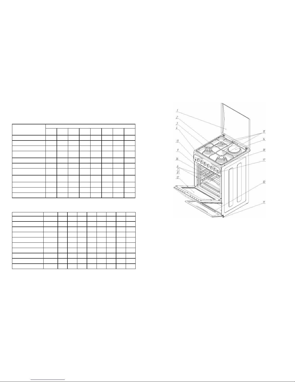
The cooker consist out of working table – table with the burners, electrical oven and
domestic chamber (pic.5).
Working table of the cooker has 4 gas burners pos. 115 or 3 gas burners and one
electrical plate pos.
Control of the cooker is made by means of handles pos. 4, 17, 18 which are located
at control board.
There is a grid pos. 2 at the table of the cooker surving for tablewares putting.
Electrical oven has two heating elements, one of which is installed in the upper part,
another in the lower part.
Electric oven has highlight device (except execution 06).
Control lamp of thermoregulator of electric oven is switching off in achievement of
fixed temperature in the oven.
In lower part of the gas electric cooker domestic chamber pos.10 is situated, which is
intended for tableware keeping.
Pic. 6
The cooker stands at four easy regual-
ated legs pos.11.
Cooker can be equipped with the Grill
heating element (with the power 1,5kW)
with electrical turnspit (pic.6). Before ap-
plication it is necessary to set turnspit at
the motor sleeve and at the support, see
Pic.6.
During cooking the handle of the turn-
spit must be removed and door closed.
The cooker can have mechanical timer
for sound signal supply. Range of set time
is 1….60 min. Timer switching on is made
by appropriate handle (pos. 8 pic.8) at the
control board by clockwise turn.
OPERATING SEQUENCE
Turn on of as burners with the system of as control.
To push and turn counter-clockwise the handle, according to the burner in use , to put
it in the position «maximum flame» and bring alight the match or to turn on the push but-
ton of ignition , for the cookers with ignition. The handle of the gas valve take on
in the pressed condition not less then 10 seconds, just for the device had a time to snap
into action.
Attention! If the burner was not li hted, it is necessary to switch it off and re-
peat i nition not less than in 1 minute.
• Adjustment of intensity of burning is made by the further turn of the handle of the
valve counter-clockwise - thus should not occur casual extinction of the burner. At turn
against the stop the burner will work on minimal flame .
• to switch off the burner, it is necessary to turn the valve handle clockwise against
the stop.
9
• Do not allow the children or the people which are not acquainted with the present
operation manual, to use the cooker during your absence.
• When operating of the grill or of the oven come-at-able details of the oven can be
hot very much. Do not allow to the children to approach to the oven. To avoid oven door
overheatin it is recommended to set the temperature of heatin element rill
thermore ulator not more then 2000C
• This device is not destined for use by people (including children) with limited physi-
cal, sensible and mental abilities or absence of experience and knowledge and people
didn’t receive corresponding indications, advices and control about use of the device by
man, who is responsible for safety.
• Children need care to guarantee their not playing with device
• During use of the device surface became hot. Measures excluding touch to heating
elements inside the oven must be taken
• Attention: open parts can become hot during use. Little children must be aside.
• The change of the cooker design and intervention of the people not authorized by
the Manufacturer on guarantee repair are forbidden.
• When using the small kitchen electro devices near the cooker, watch, that their feed-
ing cables do not touch hot parts of the equipment.
• Disconnect the cooker from network when you leave for a long time. Block gas sup-
ply.
• Do not use inflammable liquids (alcohol, petrol, etc.) near the running equipment.
• Do not put on the cooker dishes with the rough or deformed bottom. Try to have the
dishes in such a way, that handles do not overheat, and that it was impossible to overturn
ware, casually having touched the handles.
• If the cooker is not used, check up, that control handles on the board are in posi-
tion - closed.
• Never allow the children to be near the cooker when you use the oven.
• The parts of the cooker (especially electric heater) after switching off remain hot
for a long time. Be careful, do not touch the cooker, wait, till it will cool down completely.
• It is forbidden to clean the oven by means of steam.
• The Prevention:
Never put the hot ware and flammable materials in the domestic chamber.
Never leave the running gas burners empty or with not used ware as the ware quickly
heats up and can damage the equipment.
ome models of the cookers are equipped with glass cap. In avoidance of glass crack-
ing it is forbidden the following:
- to light table burners at closed cap
- to lower the cap when hobs are running or still are hot.
• Clean the lid from different items before open
• Table heating elements must get cold before close a lid.
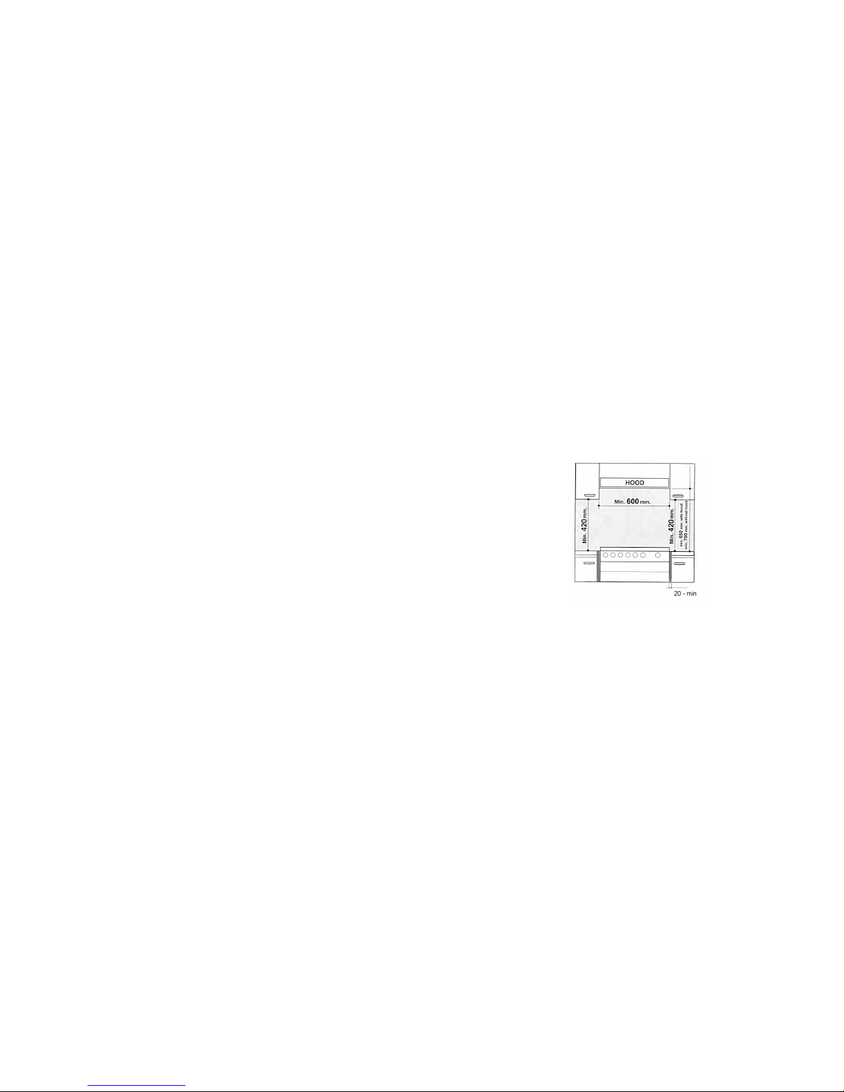
• The usage of the gas cooker demands a constant air flow. When installing the cook-
er, strictly follow the instructions mentioned in the paragraph «The Instruction on installa-
tion» of the present manual.
• At occurrence of a non-standard situation disconnect the cooker from network, and
apply to gas service on your residence.
• If you have decided, that the cooker does not suit for exploitation, make it unsuitable
for use: disconnect from the network, cut off feeding cable, remove potentially danger-
ous parts (it is especially important for safety of children which can play with not used or
thrown devices).
Attention! For maintenance of effective and safe work of the equipment we urgently
recommend:
do not use the help of the not authorized by the manufacturer people, to demand to
use the original spare parts at repairs.

10
EXECUTIONS OF COOKERS
Cooker model 1470-GE-ХХ is produced in the several executions specified in table 2.
The designation of your execution is specified in a bar code located in the present operat-
ing manual, on a cooker near the name plate and on the packing.
Attention! The cooker is executed according to the class I of electric safety. It is for-
bidden: to use the cooker without grounding.
Table 2 of Execution of cookers
Comfort elements
Executions
00 01 03 04 05 06 08 09
Turnspit (set) **
Ignition of table burners * * * * *
Oven highlight ***** **
Automatic valves for
table burners safety ********
Mechanical timer *
Cover of the table ********
Domestic chamber with
the door ** ***
Domestic chamber with
drawer ***
Electric hot plate **
Grill heating element **
Electric oven ********
Completeness
Table 3 The list of components
Components Quantity 00 01 03 04 05 06 08 09
1. Cooker 1 * *******
2. Grid of the table 1 * *******
3. Baking tray 1 ********
4. Frying tray 1 ********
5. Oven grid 1 ********
6. Turnspit (set) 1 ***
7.Regulating legs 4 ********
8. Filter (net) 1 ********
9.Operation manual 1 ********
10. Packing 1 ********
11
PRODUCT’S STRUCTURE
Pic. 5
1 - cover (not for all models)
2 - grid of the table
3 - hob (for putting of tablewares of small diameter)
4 - control handle
6 - aluminium baking tray
7 - oven grid
8 - tray for frying and fat gathering
9 - electric oven
10 - domestic chamber
11 - regulating legs
12 - oven door
13 - ignition switch on button
14 - electric hot plate
15 - burners of the table
16 - turnspit
17 - handle for timer control
18 - control handle of electrical hot plate
Table of contents