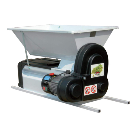
Grifo DVEP50I manual

MANUALE DI ISTRUZIONI USO E MANUTENZIONE
INSTRUCTION HANDBOOK FOR USE AND MAINTENANCE
GRAPE CRUSHER AND GRAPE STALK REMOVER
5000 KG/H WITH ROTATING SIEVE
“DVEP50I”
N° Matricola –Registration N°:
Anno di costruzione –Manufactoring year:
WARNING: To operate this machine safely and correctly it is necessary to read this instruction manual
carefully and to follow all the instructions it contains.

1
USER’S MANUAL
INDEX
1.1 PURPOSE OF THIS MANUAL.....................................................................................................................................2
1.2 MANUFACTURER IDENTIFICATION ..........................................................................................................................2
1.3 MACHINE IDENTIFICATION........................................................................................................................................2
2.1 GENERAL DESCRIPTION OF THE MACHINE ...........................................................................................................3
2.2 HOW THE MACHINE IS SUPPLIED ............................................................................................................................3
2.3 PRINCIPAL COMPONENTS ........................................................................................................................................3
2.4 DESCRIPTION OF THE MODELS ......................................................ERRORE. IL SEGNALIBRO NON È DEFINITO.
2.5 SAFETY DEVICES .......................................................................................................................................................4
2.6 TECHNICAL CHARACTERISTICS ..............................................................................................................................4
3.1 WARNINGS ..................................................................................................................................................................5
4.1 ASSEMBLY OF DISASSEMBLED PARTS..................................................................................................................6
4.2 CLEANING INSTRUCTIONS........................................................................................................................................6
4.3 INSTRUCTIONS FOR CONNECTING THE TUBE FROM THE PUMP TO THE CONTAINER....................................6
4.4 ELECTRICAL CONNECTIONS (SEE ELECTRICAL DIAGRAM PAR.7......................................................................6
5.1 STARTING UP AND OPERATING INSTRUCTION......................................................................................................7
5.2 POSSIBLE PROBLEM AND CURES...........................................................................................................................7
6.1 CLEANING, MAINTANCE, STORAGE ........................................................................................................................9
7.1 ELECTRICAL DIAGRAM ...........................................................................................................................................10
8.1 DECLARATION OF CONFORMITY...........................................................................................................................11

2
1.1 PURPOSE OF THIS MANUAL
This manual has been written by the manufacturer and is an integral part of the machine itself. The
instructions it contains are meant for those people who will install, operate, clean, maintain and store the
machine. Strict observance of the instructions will guarantee excellent results as well as the safety of the
operators.
1.2 MANUFACTURER IDENTIFICATION
1.3 MACHINE IDENTIFICATION
The machine type can be ascertained by the details given on the plate.
The plate gives the following data:
• manufacturer
• E.C. markings
• machine type
• frame number
• year of manufacture

3
2.1 GENERAL DESCRIPTION OF THE MACHINE
The "DVEP50I" horizontal, grape stalk removing machine is of
compact dimension and capable of a medium hourly production.
It's main innovative characteristics are:
• it's frame, which is made up of two parts and can be opened
• the basket, which can be removed from the machine
• the built-in pump to allow the movement of the product. All this
makes this machine practical and easy to use, to clean and to
check internally. (Fig. 2)
2.2 HOW THE MACHINE IS SUPPLIED
The "DVEP50I" grape stalk removing machine is supplied by your dealer in two parts:
• main body of the machine in it's normal state, without packaging
• upper protective part, disassembled and packed in a box, complete with nuts and bolts necessary for easy
assembly.
WARNING: the upper protective part is an integral part of the machine and must not be separated from it. To
sell this part separately is strictly forbidden.
This machine can be lifted with either a crane or a forkless lift truck by means of straps, ropes or cables, (in
observance of current safety regulations.)
These should be slung around the axle with the mixing screw wick can be found inside the grape hopper.
You must allow for the fact that the side with the motor will have a much greater weight.
2.3 PRINCIPAL COMPONENTS
1. Protective at the grape stalks exit point.
2. Basket guide ring (made of plastic)
3. Basket (bored sheet metal with round flared holes)
4. Upper protective part
5. Pinion for grille transmission (made of plastic material)
6. Upper frame
7. Upper guard
8. Toothed gear with hub for transmission to upper worm (made of plastic material)
9. Toothed gear for sieve (made of plastic material)
10. Lower guard
11. Electric motor complete with all necessary instrumentation for all operations plus emergency stop
button
12. Belt's tension adjusting screw (placed under the motors supporting shelf)
13. Stainless steel pump for the movement of the marc
14. Fixed wheels (rear)
15. Rotating wheels (front) complete with brakes for locking
Fig. 2

4
2.5 SAFETY DEVICES
• The protective covers (FIG.3 positions 7 and 10) prevent any
involuntary contact or his clothing and the other moving parts
• The hood at the grape stalks exit point (FIG. 3 position 1)
prevents any involuntary contacts
between the operator or his clothing and the paddles of the
grape stalk removing axle.
• The upper protective part or box ( FIG.3 position 4) allows
partial access to the working area only to the operator
• The well locking brackets (FIG.3 position 16) ensure the
stability of the machine while in operation
• The emergency button (FIG.3 position 11) allows you to stop
the machine quickly in an emergency situation
2.6 TECHNICAL CHARACTERISTICS
Dimensions (AxBxC) 145x76x147
Weight 136 Kg
Hourly production capacity 4000/4500 Kg
Electric motor: power output in KW 1,8
Electric motor's monophase - triphase 220/380 V
Pump tube diameter 60 mm
Pumping head 4 Mt
The noise level measured is 93 dB (A)
Fig. 3

5
3.1 WARNINGS
The instructions given in this manual must be followed very carefully when installing, operating, cleaning,
maintaining or storming the machine.
•The manufacturer declines all responsibility foe injury to persons or animals or damage to things caused
by the non-observance of the instructions in this manual.
• All electrical connections must always be carried out by qualified personnel (see par. 4.4)
• The efficiency of all system must always be checked, especially after a long period of Storage, by
qualified technical engineers.
• Always wear cut-resistant gloves during installation, operation, cleaning, maintenance and storage.
•Wash the machine each time before use (see par. 4.2).
• It is strictly forbidden to start the machine until the protective covers (including the upper protective
part - Fig. 5) have been adequately assembled and fixed.
• Before doing any work on the machine, whether during installation, cleaning, maintenance or storage
operations, make sure it is electrically isolated (i.e. remove plug from the mains).
•It is forbidden to move machine when it is working.
•It is forbidden to remove the frame while the machine is operating: before removing any part the plug
must be withdrawn from the mains.
The operator in charge of loading the machine must:
• wear tight-fitting clothes with cuffs adhering tightly around the wrists
• use cut-resistant gloves when actually working, doing maintenance, etc.
• use non-slip shoes
• prevent children, animals or strangers from going near the machine (Fig. 6)
• must not enter the space inside the upper protective part while the machine is working. If necessary a
suitable tool can be used (stick, brush) but always remaining with one' s body outside the working area
(Fig. 7)
• must not use false ceilings or raised floors near the machine (Fig. 8)
• must not go near the grape stalks exit point with his hands (Fig. 9).
Fig. 5
Fig. 6
Fig. 7
Fig. 8
Fig. 9

6
4.1 ASSEMBLY OF DISASSEMBLED PARTS
• Open the box containing the upper protective part, then proceed
to assembly all the parts (Fig.10).
4.2 CLEANING INSTRUCTIONS
To clean the machine proceed as follows:
• make sure the mains plug is removed
• removed with a suitable spanner (n.13) screws A and B ( Fig.11)
• open up the machine, remove the hood at the grape stalks exit
point and then remove the grille (Fig.12)
• proceed to accurately clean all surfaces with a jet of water or,
preferably, with a hydro cleaner, avoiding getting the jet directly
onto electrical parts
• as cleaning agent, use a neutral detergent
• after rising thoroughly, slightly tilt the machine (by lifting it at the
front) to allow the water to flow out the pump 'a exit point.
Reassemble everything taking great care to ensure that the grille
is well placed in its seat resting on the four guide wheel (Fig.13)
• fix the upper protection part onto the machine (FIG.4) in such a
way so that the lower edge is on the same side as that of the
motor.
4.3 INSTRUCTIONS FOR CONNECTING THE TUBE FROM THE
PUMP TO THE CONTAINER
• Insert the half-pipe fitting in the tube, blocking it with a suitable
hose clip on the outside (FIG.15/A). Then connect everything to
the pump with the clamp provided (Fig.15).
Use spiralled pipes in PVC suitable for drinkable liquids, so as to
avoid obstructions caused by bending or squashing. Fix the other
and of the tube to the container designed to receive the marc,
making sure that the extremity of the tube is always clear and that
it is not submerged into the liquid itself (Fig. 16-17).
4.4 ELECTRICAL CONNECTIONS (SEE ELECTRICAL
DIAGRAM PAR.7
All electrical connections and checks must be carried out by a qualified electrical engineer.
Before carrying out any work, check that the mains power supply and frequency available corresponds with
those given on the plate near the motor. Check that lead with which the machine will be connected to the
mains (and any eventual extension cord) is capable of the maximum absorption current (see par.2.6).
Check that the earthing system in the cellar and in the mains is in perfect condition.
On the mains supply cable to the motor use a plug which conforms to safety standards and is of suitable
amperage. The green/yellow wire is the earth wire. The plug can be connected to a suitable
extension cord in turn connected to the mains, provided there is a lifesaving, differential, automatic circuit
breaker switch.
(This is especially important since cellars are usually damp places and the floors around the machine may
often be wet).
Fig. 10
Fig. 11
Fig. 14
Fig. 15
Fig. 16
Fig. 17
Fig. 12
Fig. 13

7
5.1 STARTING UP AND OPERATING INSTRUCTION
Check that the machine is stable after positioning it on a level floor, after which block the front wheels using
the brackets provided (FIG. 3 position 16). The operator should position himself on the side where the
protective part is lower and should make sure that he is the only person to feed the machine. According to
the type of mains supply, the operator should start the motor as follows:
MONOPHASE ELECTRICITY SUPPLY:
• Make sure the "Stop" button is off. If is not, rotate the round switch a 1/4 of a turn and it will automatically
come onto the off position.
• Push button 1 keeping it pressed for about 2-3 seconds (take-off torque) then release and the machine will
now be working (Fig. 18).
TRIPHASE ELECTRICITY SUPPLY:
• Make sure the "Stop" button is off.
• Push button 1 then release it.
• The machine is now working.
Check that the direction of the rotation is correct. If not, remove plug, open it and exchange the position of
the two phase wires. Reassemble everything, after which the may begin (Fig. 18).
To stop the machine press the "Stop" or "Emergency" button.
At this point the machine is working, so you can proceed and load the grapes into the feeder hopper (Fig.
19). Never use the machine without the upper guard (Fig. 20).
While working check that the grape stalks do not obstruct the exit point completely: at regular intervals,
remove them using a harpoon or garden fork (Fig. 21).
WARNING: never do this operation with your hands (Fig. 9), and ensure that no one else does this operation
unaware of the dangers. When the machine is in movement, the operator must not reach inside the feeder
hopper with his hands (Fig. 7).
When there are no more grapes and the work has ended. to clean the inside of the machine from eventual
residues, switch off the motor and with the help of a brush push to re-start it, return the switch to "O" and
repeat the starting sequence.
When it is necessary to stop the machine suddenly, press the emergency button placed on the motor (Fig.
18). To start up again reset the emergency button.
5.2 POSSIBLE PROBLEM AND CURES
For any eventuality other than the ones described below, you must request assistance from a qualified
technical engineer, or directly from your area dealer.
LOSS OF MUST AND GRAPE SKIN AT THE GRAPE STALK EXIT POINT
While working, it may happen that at the grape stalk exit point, as well as grape stalks, some grape skins and
must could also come out.
This indicates that the machine is clogged up.
The possible causes are:
• a loss of revs by the pump caused by a loose bet (this can also be noticed by the smell of burning rubber).
Proceed as follows:
• switch off the motor and remove plug from mains
• remove the lower guard (Fig. 3 position 10) and check that the belt is tight. If necessary, adjust by
operating the adjusting screw placed under the motor's shelf support ( Fig. 3 position 12);
A LACK OF LIQUID WITHIN THE GRAPES (VERY DRY SEASONS).
The pump finds it difficult to push the liquid along the tube, lowering considerably it's carrying capacity and
thus clogging up the machine. Proceed as follows:
• switch off the motor

8
• remove the tube from the container and lower it to the ground placing a bucket at the end of the tube
• re-start the motor and put some must in the feder hopper
• wait for the mare to carne out in a more liquid form than before, then stop the motor once again
• replace the tube in its normal position, re-start the machine being careful to add., from time to lime, some
must to the other grapes.
ENTERY OF FOREIGN BODIES INTO THE MACHINE
Entry of foreign bodies caused loud noises and vibrations and can also cause serious damage to the
machine (e.g. scissors or knives used for the harvest of grapes end left in the baskets).
Proceed as follows:
• press the emergency button as soon as possible
• remove plug from the mains
• empty the upper feeder hopper
• open up the machine (par. 4.2) and remove the foreign body
• remove the hold at the grape stalkes exit point, remove the grille and check that it has not been damaged
• carry out any necessary repairs. If spare parts are needed, ask at your area dealer.
Check that the foreign body has not reached the pump. If so, dismantle as follows:
• remove the lower guard (Fig. 3 position 10)
• remove the stay-rod of the feeder hopper flap, remove the pins or screws of the feeder hopper's hinges
then put aside the upper frame
• detach the tube from the pump, being careful not to let the marc still in
the pump and tube drip
everywhere (Fig. 22)
• wash and clean the lower frame, then remove the belts
• using a pin-removing tool, remove the elastic pin which holds the pulley
(Fig. 23-A) and remove the pulley
• remove the segeer Ø 25 from the axle (Fig. 23-B)
• remove the pump fixing screws (Fig. 23-C), detach the pump from the
chassis together with
the axle (Fig. 24)
• slide out the pump from the axle (Fig. 25) and check the condition of the
pump and of the impeller (repair or replace as required. To remove the
impeller, first remove the elastic pin (Fig. 25-A).
• once everything has been repaired, replace the axle into the chassis,
being very careful to replace the end opposite the pump in its proper seat
within its support
• clean the head where the pump rests. Take some silicone suitable for
alimentary/uses and pour a small quantity along the centre line of the
pump's fixing holes (Fig. 26)
• clean the surface of the pump and re-assemble
Fig. 22
Fig. 23
Fig. 24
Fig. 26
Fig. 27

9
6.1 CLEANING, MAINTANCE, STORAGE
It is necessary to clean the machine not only when the day's work is over, but also whenever
the interval between a working period and another lasts for a few hours. Before cleaning, make sure you
remove the plug from the mains, then proceed as described in par. 4.2. The machine does not require
special maintenance, export for checks on the conditions of support and bearings which, should they appear
worn, must be replaced. To store the machine, proceed as follows:
• after having washed and cleaned the machine with great car, allow it to dry and reassemble all
its component parts. For reasons of space, remove the upper protective part and replace it in its box.
Everything can then be stored away and covered with a nylon sheet to protect from dust or other harmful
agents.
For any occurrence not described in this manual, please refer to a qualified technical engineer or directly to
your local area dealer.
SCRAPPING
In the event of this machine requiring to be scrapped, we recommend to be scrapped, we recommend you
render it fully inoperative and then dispose of it in accordance with current legislation regarding the
differentiated collection of waste products.
90% of the machine is made up of recyclable ferrous materials. It can therefore be disposed of as scrap iron
collection centers.
The machine does not contain materials or other elements which might be a source of danger during
scrapping.
The machine described in this manual are subject to variations. Illustrations and technical specifications must
not be taken as binding and we reserve the right to make any necessary change without giving prior notice.

10
7.1 ELECTRICAL DIAGRAM
Here below we give the electrical diagram relative to the machine’s motor, as given by the manufacturer.

11
8.1 DECLARATION OF CONFORMITY
La macchina a cui è allegato il presente libretto rispetta la direttiva CEE 89/392 e successive
modificazioni in materia di sicurezza e tutela della salute. Il marchio C E apposto sulla macchina e la
garanzia di conformità.
The machine, the handbook of which is enclosed herewith, is in line with the 89/392 EEC safety and
health protection regulations and following modifications.
The C E brand on the machine guarantees that it conforms with the above regulations.
La macchina da Lei acquistata:
The machine you have purchased:
Modello/Model ________________
Anno/Year ____________________
è stata costruita interamente da:
has been entirely built by:
GRIFO Macchine Enologiche snc
di Marchetti Giordano & C.
Via Mantova n. 1
26034 Piadena (CR) –ITALY
Tel. 0039-375-98601
Fax 0039-375-980879
www.grifomarchetti.com –info @grifomarchetti.com
Rivenditore autorizzato a cui rivolgersi
Authorized retailer
Table of contents
Other Grifo Farm Equipment manuals
Popular Farm Equipment manuals by other brands

FERRANTI
FERRANTI DOG KENNEL COCKER Assembly manual

Ferrari
Ferrari F-MAX Operating and service manual

MASSEY FERGUSON
MASSEY FERGUSON 9186 Service manual
APV
APV ES 100 M3 EVO Original operating manual
Hedensted Gruppen
Hedensted Gruppen HG FEEDER 600 user manual
Agria
Agria 8100 Series operating instructions
horsch
horsch Finer SL operating instructions

J.ASSY
J.ASSY KIT APOLLO user guide
AGCO
AGCO GLEANER 3000 Service manual
Finn
Finn HydroSeeder T170 ML Operator Instructions And Parts Manual

Buhler
Buhler Round Bale Carrier 1500 Operator and parts manual
STEIN Automation
STEIN Automation 300 SoftMove operating instructions
