STEIN Automation 300 SoftMove User manual
STEIN300 SoftMove_Stop Devices_08_GB.doc / 10.2018 1
Stop Devices (SE) / P-Positions SOFTMOVE
STEIN Workpiece Transport System (STEIN 300 SoftMove)
Operating instructions
Attention all installation, operating and maintenance personnel -
always keep these instructions with the stop device!

2 STEIN300 SoftMove_Stop Devices_08_GB.doc / 10.2018
©STEIN
Automation
The copyright in these documents is reserved by STEIN Automation.
Original language of the documentation: German
These documents may not be altered, distributed, reproduced or transferred to third par-
ties without the prior written permission of STEIN Automation.
STEIN Automation GmbH & Co. KG
Carl-Haag-Straße 26
78054 VS-Schwenningen, Germany
Telephone: (+)49 (0)7720 / 8307 – 0
Publication date: October 2018
The right to make changes in design and construction is reserved.

STEIN300 SoftMove_Stop Devices_08_GB.doc / 10.2018 3
Table of contents
1Abbreviations and symbols ............................................................................................................................5
1.1 Explanation of safety and warning notices .......................................................................................... 5
2Introduction ......................................................................................................................................................6
2.1 Short description................................................................................................................................ 7
2.2 Initial inspection................................................................................................................................. 8
2.3 Complaints......................................................................................................................................... 8
2.4 Warranty ............................................................................................................................................ 8
3Safety information ...........................................................................................................................................9
3.1 General safety information ................................................................................................................. 9
3.2 Appropriate use and liability exclusions .............................................................................................. 9
3.3 Product misuse ................................................................................................................................ 10
3.4 Residual danger ............................................................................................................................... 11
4Technical description ................................................................................................................................... 12
4.1 Contents .......................................................................................................................................... 12
4.2 System components......................................................................................................................... 12
5Stop situations .............................................................................................................................................. 14
5.1 Stop device for workstations ............................................................................................................ 14
6ASI stop device.............................................................................................................................................. 15
6.1 Technical data - ASI stop device....................................................................................................... 16
7Installing the stop devices........................................................................................................................... 17
7.1 Procedure ........................................................................................................................................ 17
7.2 Preparation ...................................................................................................................................... 17
7.3 Installing the stop device.................................................................................................................. 18
7.4 Installing the stop devices and centring rails .................................................................................... 19
7.5 Connecting the stop device to the compressed air supply ................................................................ 20
7.6 Connecting the stop device to the electrical power supply (ASI Bus) ................................................ 21
8Accessories.................................................................................................................................................... 22
8.1 ASI stop device overview.................................................................................................................. 22
8.2 300 423 001 ASI stop device (ASI-S)................................................................................................ 23
8.3 300 424 001 ASI pre-stop device (ASI-VS) left ................................................................................. 24
8.4 930 104 001 ASI pre-stop device (ASI-VS) right ............................................................................... 25
8.5 300 425 001 ASI workstation stop device (ASI-AS) .......................................................................... 26
8.6 300 642 001 ASI workstation pre-stop device SoftMove (VSSM)...................................................... 27
8.7 300 426 001 ASI workstation stop device left (ASI-AS-L) ................................................................. 28
8.8 300 427 001 ASI supply side stop device (ASI-ES) ........................................................................... 29
8.9 300 428 001 ASI workstation stop device with offset stop (ASI-ASA) ............................................... 30
8.10 300 429 001 ASI workstation stop device with offset stop (ASI-ASB) ............................................... 31
8.11 300 429 001 ASI workstation stop device with offset stop (ASI-ASC) ............................................... 32
8.12 Components of the accessory items................................................................................................. 33
9P-Positions Soft Move................................................................................................................................... 41
9.1 P1S / P3S (Corner 90° BEQE) ...................................................................................................... 41
9.2 P2S / P4S (Corner 90° QEBE) ...................................................................................................... 42
9.3 P5S / P7S (A-workstation entry) ...................................................................................................... 43
9.4 P6S / P8S (A-workstation exit)......................................................................................................... 44

4 STEIN300 SoftMove_Stop Devices_08_GB.doc / 10.2018
9.5 P9S / P10S (Corner 180°) ............................................................................................................... 45
9.6 P11S / P12S (B-workstation entry) .................................................................................................. 46
9.7 P13S / P15S (C-workstation entry) .................................................................................................. 47
9.8 P14S / P16S (C-workstation exit) .................................................................................................... 48
9.9 P21S / P23S (A-workstation corner entry) ....................................................................................... 49
9.10 P22S / P24S (A-workstation corner exit).......................................................................................... 50
9.11 P25S / P27S (B-workstation corner entry) ....................................................................................... 51
9.12 P26S / P28S (B-workstation corner exit).......................................................................................... 52
9.13 P29S / P31S (C-workstation corner entry) ....................................................................................... 53
9.14 P30S / P32S (C-workstation corner exit) ......................................................................................... 54
10 P-Positions Soft Move 4G ............................................................................................................................. 55
10.1 P5S 4G / P7S 4G (A-workstation entry)............................................................................................ 55
10.2 P11S 4G / P12S 4G (B-workstation entry)........................................................................................ 56
10.3 P13S 4G / P15S 4G (C-workstation entry) ....................................................................................... 57
10.4 P21S 4G / P23S 4G (A-workstation corner entry)............................................................................. 58
10.5 P25S 4G / P27S 4G (B-workstation corner entry)............................................................................. 59
10.6 P26S 4G / P28S 4G (B-workstation corner exit)............................................................................... 60
10.7 P29S 4G / P31S 4G (C-workstation corner entry) ............................................................................ 61
11 Initial operation .............................................................................................................................................62
12 Faults .............................................................................................................................................................. 62
13 Cleaning and maintenance ...........................................................................................................................63
13.1 Cleaning........................................................................................................................................... 63
13.2 Maintenance .................................................................................................................................... 64
14 Appendix......................................................................................................................................................... 64
14.1 Technical data.................................................................................................................................. 64
STEIN300 SoftMove_Stop Devices_08_GB.doc / 10.2018 5
1Abbreviations and symbols
Action symbol
1 Symbol for actions that must be carried out in a specified sequence.
⇒Consequence or result of an action
•Count
SE Stop devices
WT Pallets
BE Belt element
BA Operating instructions
Fig. Figure
i This sign indicates information that will allow the stop device to be used more effectively
and more economically.
The symbols used in the operating instructions for safety and hazard warnings are de-
scribed in detail in Chapter 3.
1.1 Explanation of safety and warning notices
The following safety signs explain all the situations or actions where danger to life and
limb for machine operators or their colleagues exists.
Strictly comply with these instructions and act with particular care in these cases. Pass
all safety notices on to all other users.
DANGER!
The symbol with the added designation DANGER describes a directly impending
hazards!
The hazard results in serious injury to people or even fatalities.
WARNING!
The symbol with the added designation WARNING describes a potentially
impending hazards!
The hazard may result in serious injury to people or even fatalities.
CAUTION!
The symbol with the added designation CAUTION describes a potentially
hazardous situation!
The hazard can result in injury to people.

6 STEIN300 SoftMove_Stop Devices_08_GB.doc / 10.2018
The safety signs appear frequently in the text with a picture to explain what the source of
the hazard is.
CRUSHING HAZARD!
This symbol gives warning of a location where there is a risk of being crushed.
HIGH ELECTRICAL VOLTAGE!
This symbol gives warning of possible electric shock.
It appears for all working and operating procedures that must be followed precisely, in
order to avoid injury to personnel or damage to the system through high electrical volt-
age.
Other warning signs:
ATTENTION!
This symbol indicates warnings which, if ignored, will cause a hazard to the machine.
Protective clothing must be worn!
Wear your personal safety clothing:
Safety footwear, hard hat, goggles and safety gloves.
Environmental protection!
This sign indicates warnings that will help to avoid harming the environment.
2Introduction
The safety of all persons who come into contact with the stop devices depends funda-
mentally on knowing how the stop devices function. Therefore:
Read these operating instructions before using the devices for the first time.
These operating instructions contain important information which will ensure the correct,
economical and safe operation of your stop devices.
STEIN300 SoftMove_Stop Devices_08_GB.doc / 10.2018 7
2.1 Short description
The stop devices by STEIN Automation are optional accessories for the STEIN 300
SOFTMOVE Workpiece Transport System.
Together with the STEIN 300, these devices enable the stopping, separation and posi-
tioning of the pallets and thus the workpieces found on the pallets.
Fig. 2-1:
Stop device
1 Belt element
2 Pallet
3 Stop device
The simplest type of these devices is a stop device, which stops the pallet (WT) in a de-
fined position at a workstation.
Fig. 2-2:
Stop devices and cen-
tring rails
1 Belt element
2 Pallet
3 Stop device
4 Centring rails
For workstations, which require a more exact positioning of the pallet in the X and Y axis,
the use of a stop device with two centring rails will serve the purpose. The centring rails
are screwed on internally on both sides on the belt profile.
1
2
3
1
4
2
3
4

8 STEIN300 SoftMove_Stop Devices_08_GB.doc / 10.2018
2.2 Initial inspection
Unpack all the components supplied.
Environmental protection.
Dispose of all packaging material in an environmentally responsible way.
Then carry out an initial inspection.
Check that:
all components detailed on the delivery note have been supplied
components have not been damaged or lost in transit.
2.3 Complaints
In order for claims for damage caused in transit to be accepted, follow this procedure:
Inform the freight company.
Draw up a damage report giving the following details
•Name and address of recipient
•Item or order number
•A description of the damage.
Send components, if possible in their original packaging, with the damage report,
back to the manufacturer.
2.4 Warranty
For the stop device and its spare parts we grant the legal guarantee period or rather the
defined guarantee period in the contract, starting with the day of delivery.
During this warranty period we will replace any components defective in manufacture or
materials free of charge.
STEIN Automation's general warranty conditions also apply.

STEIN300 SoftMove_Stop Devices_08_GB.doc / 10.2018 9
3Safety information
3.1 General safety information
The stop devices from STEIN Automation are high-quality products, manufactured
to recognised technical rules.
The stop devices left the manufacturer’s factory in good condition from a safety
and technical point of view.
All versions of the stop devices comply with the requirements of UVV, the German
accident prevention regulations.
To maintain this situation, installation staff, users and service technicians must ob-
serve the notices and warnings contained in these operating instructions.
Stop devices must only be installed and repaired by authorised personnel who
have been trained by STEIN Automation.
Only genuine spare parts from STEIN Automation may be used when carrying out
repairs to the stop devices.
3.2 Appropriate use and liability exclusions
The stop devices should only
used in STEIN 300 belt systems,
be operated together with suitable pallets with permitted dimensions and weights,
only be used for the purpose relevant to the model,
be operated indoors,
be operated in dry areas,
be used in areas where there is no risk of explosion.
be operated in an environment that is free of oil and shavings.
Centring precision and stresses on the system can be found in the Chapter 14.1
Technical data.
i Unauthorised interventions, alterations or repairs carried out to the stop devices invali-
date the warranty.
STEIN Automation shall not be liable for damages sustained due to unauthorised inter-
ventions, changes or repairs!
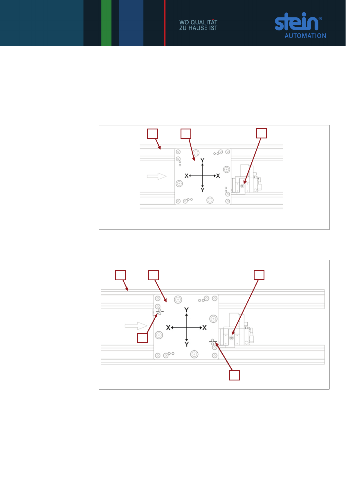
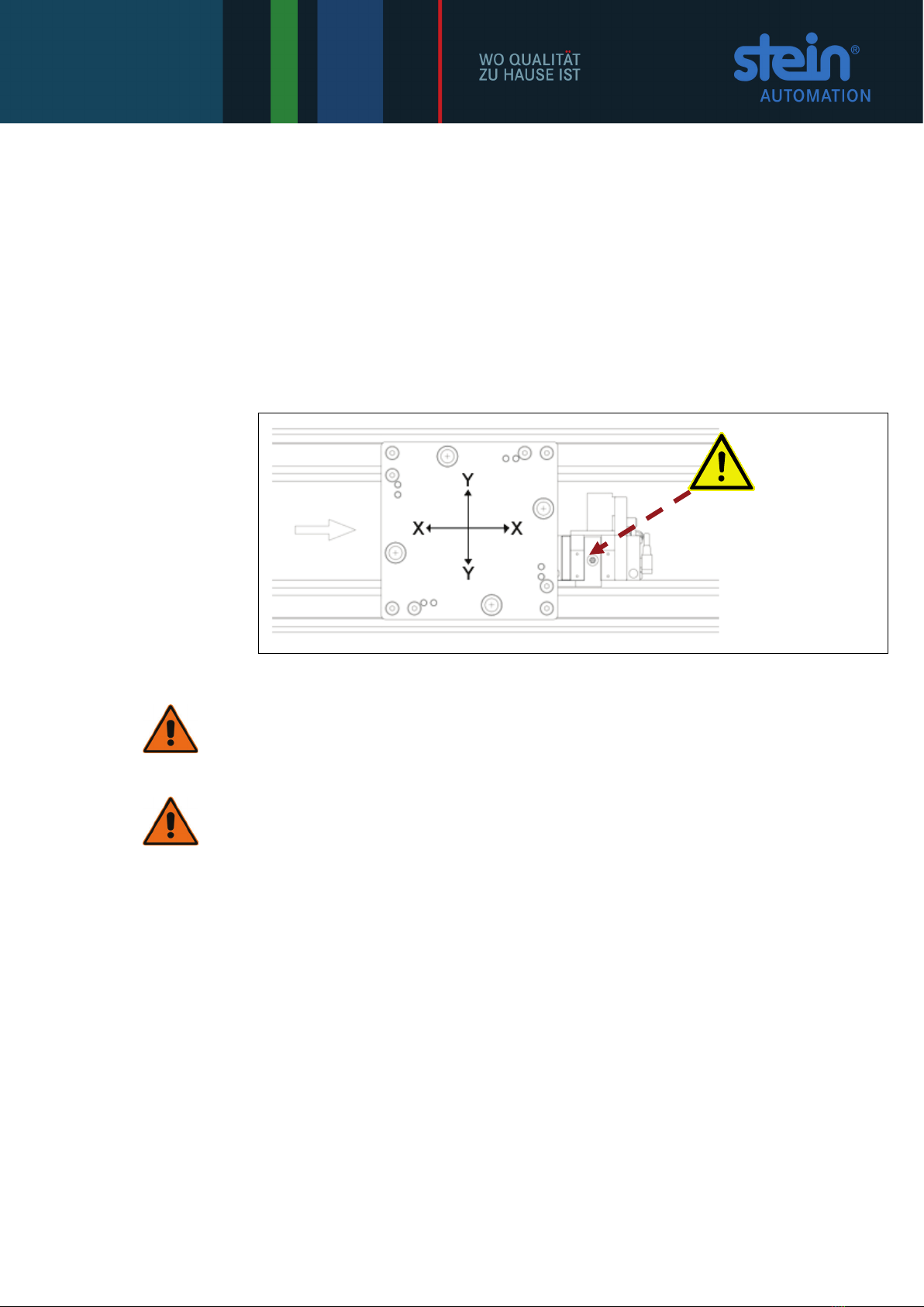
Fig. 3-1:
Maximum
loads for the stop de-
vices
10 STEIN300 SoftMove_Stop Devices_08_GB.doc / 10.2018
For the stop device, the permitted pallet load (pallet + workpiece - at medium load and
STEIN operating pressure of 4 bar) is
•in the X axis: none
•in the Y axis: 100 N
•in the Z axis: 50 N
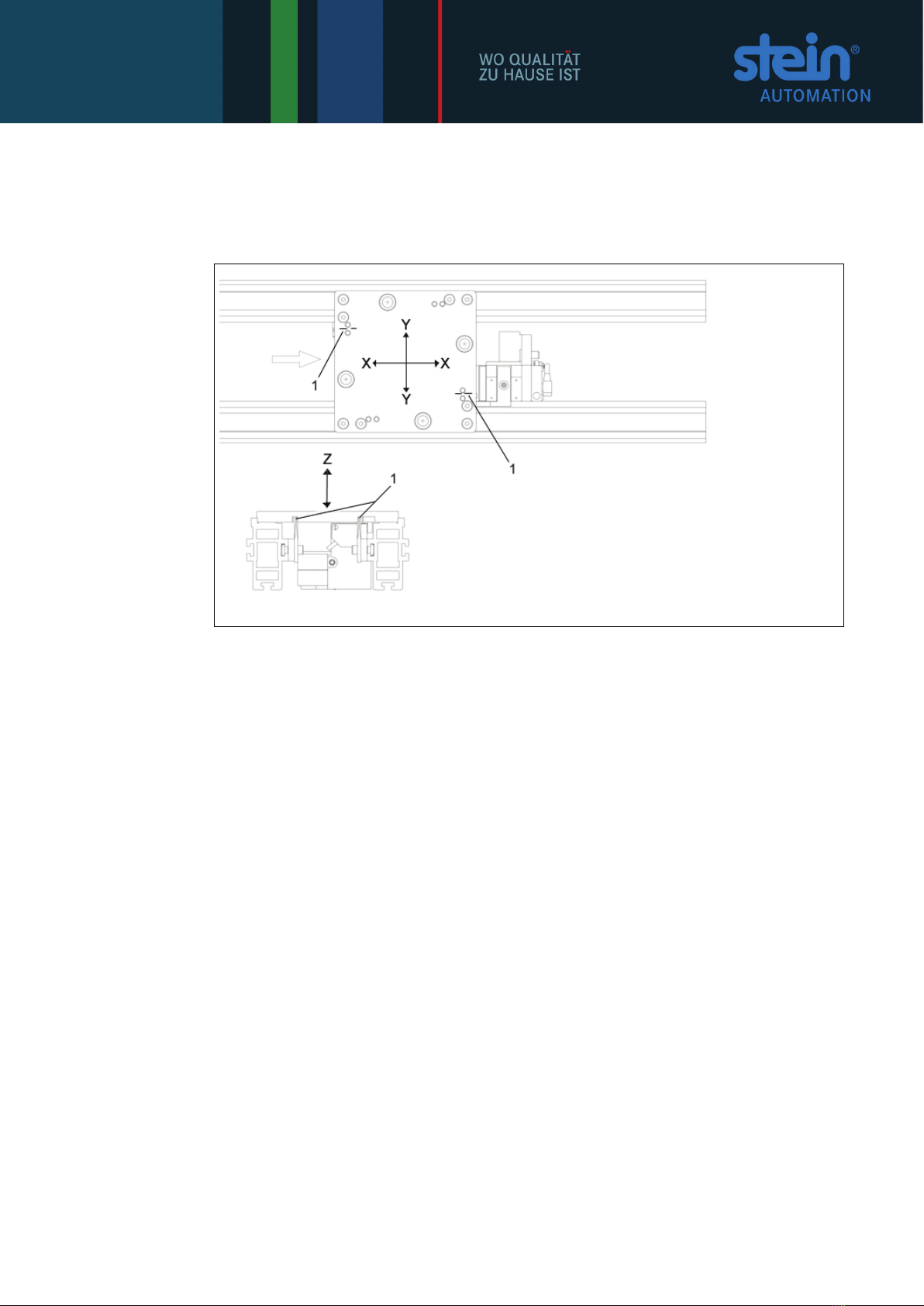
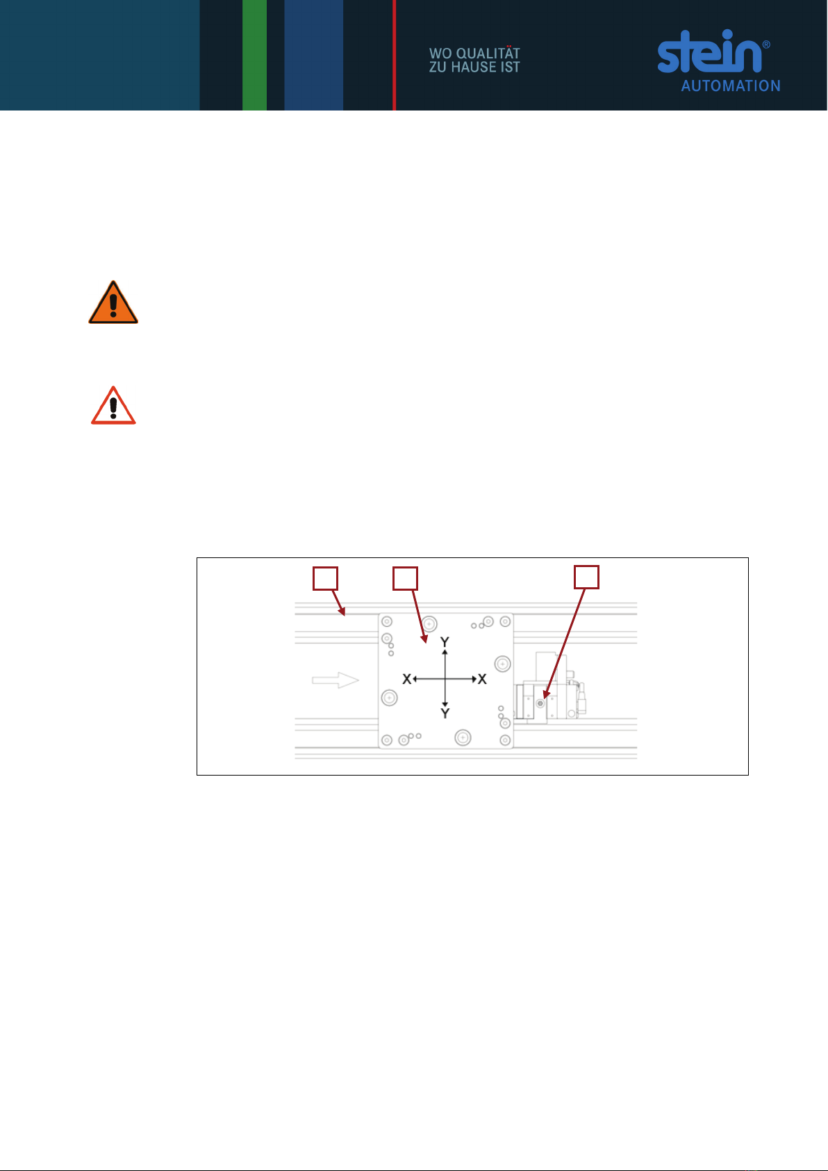
Fig. 3-2:
Maximum loads for
stop devices with cen-
tring rails(Pos 1)
For stop devices with a centring rail, the permitted pallet load (pallet + workpiece - at
medium load and STEIN operating pressure of 4 bar) is
•in the X axis: none
•in the Y axis: 100 N
•in the Z axis: 50 N
i Unauthorised interventions, alterations or repairs carried out to the stop devices invali-
date the warranty.
STEIN Automation shall not be liable for damages sustained due to unauthorised inter-
ventions, changes or repairs!
3.3 Product misuse
The stop devices may not be used
in queue mode.
STEIN Automation shall not be liable for damages sustained due to unauthorised inter-
ventions, changes or repairs!
STEIN300 SoftMove_Stop Devices_08_GB.doc / 10.2018 11
3.4 Residual danger
The stop devices are manufactured using state-of-the-art technology and to recognised
safety standards Nevertheless their use can lead to dangerous situations for users or
third parties or to impairments of the system and other material assets.
During the transport of pallets and products, the following injuries can result:
•Crushing and collision:
- from jamming between the pallet and the stop devices,
- from moving the pneumatic cylinders,
- from parts protruding over the pallets.
•Injuries due to the condition of the product being transported.
Fig. 3-3:
Possible places for
- jamming
Mechanical protection.
WARNING!
The stop devices are supplied without protective covers. These must be adapted
by the customer to the specific requirements and installed.
WARNING!
Operating the facility without correct and fully mounted protective covers is not
permitted.
12 STEIN300 SoftMove_Stop Devices_08_GB.doc / 10.2018
4Technical description
4.1 Contents
The stop devices must be installed by the customer or are delivered fully installed and
ready to connect.
WARNING!
The stop devices are supplied without protective covers. These must be adapted
by the customer to the specific requirements and installed.
WARNING
The scope of delivery for the stop devices does not include a controller! This must be
ordered separately.
The stop devices are fitted with ASI electronics and controlled via the ASI bus.
4.2 System components
Fig. 4-1:
Stop devices
1 Belt element
2 Pallet
3 Stop device
The simplest type of these devices is a stop device, which stops the pallet (WT) in a de-
fined position at a workstation.
Application:
At manual workstations, e.g. to place or install parts.
Pallet position:
Pallet precision in the belt system +/- 1 mm in the Y axis.
By stopping off-centre the pallet can skew the pallet.
The position of the pallet can change by 0.5 mm in the Z axis.
i The pallet can be moved against the direction travel from the stop device (X axis).
1
2
3

STEIN300 SoftMove_Stop Devices_08_GB.doc / 10.2018 13
Fig. 4-2:
Stop devices and
centring rails
1 Belt element
2 Pallet
3 Stop device
4 Centring rails
For workstations, which require a more exact positioning of the pallet in the X and Y axis,
the use of a stop device with two centring rails will serve the purpose. The centring rails
are screwed on internally on both sides on the belt profile.
Function:
To stop the pallet with centring in the centring rail.
Application:
For manual and automatic workstations where a more precise position of the pallet is re-
quired.
Pallet position:
Pallet precision in the X axis +/- 0.25 mm and Y axis +/- 0.15 mm.
The position of the pallet can change by up to 0.5 mm in the Z axis.
i The pallet can be moved against the direction of travel from the stop device (X axis).
1
4
2
3
4
14 STEIN300 SoftMove_Stop Devices_08_GB.doc / 10.2018
5Stop situations
The installing sets shown under the heading "Stop situations" facilitate the pallet’s stop-
ping at a manual or automatic workstation in order to, for instance, carry out configura-
tions or installation work on the workpiece.
The sets are always composed of various accessory parts depending on customer-
specific control elements (e.g. electric or pneumatic foot switches to stop or release the
pallets).
The following diagrams show the maximum configuration of the stop situation.
Please the documents specific to the order for the actual configuration.
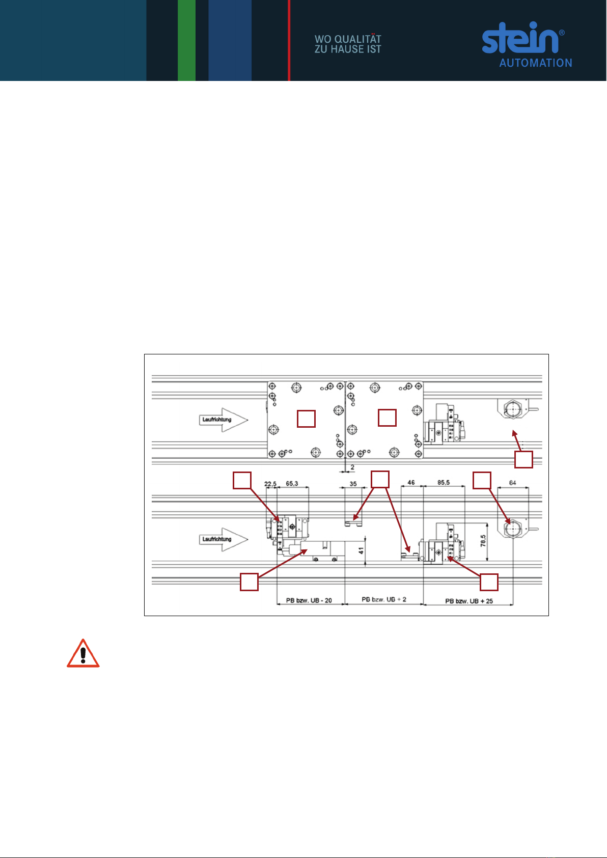
5.1 Stop device for workstations
Design of a standard stop situation (stop position).
Fig. 5-1:
Stop position
1 Workstation stop de-
vice
2 Workstation (ws) pre-
stop device
3 Read head
4 Surface switch
(optional)
5 Centring rails
6 Pallet on the ws stop
device
7 Pallet on the ws pre-
stop device
8 Free space behind the
processing position
WARNING
To permit the reliable functioning of the logistics, it is essential to maintain the prescribed
allocation of read head and stop position.
The read head must be positioned so that only the pallet which is in the processing posi-
tion at the workstation stop device is read. The code carrier from the subsequent pallets
must only pass over the read head once it enters the processing position.
6
1
2
3
4
5
7
8
STEIN300 SoftMove_Stop Devices_08_GB.doc / 10.2018 15
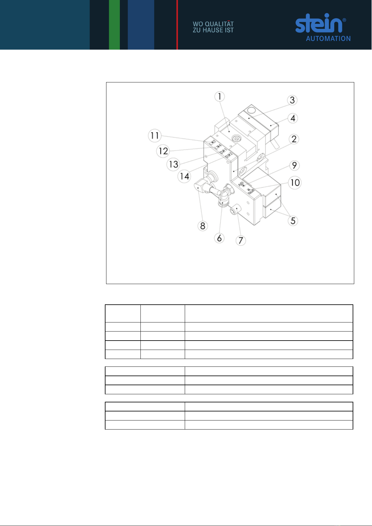
6ASI stop device
Fig. 6-1:
ASI stop device
1 Pneumatic stop
device
2 ASI electronics
3 Intermediate plate
4 Proximity switch
5 Pn valve
6 Air connection
7 Connection to the ASI
cable
8 Plug for the proximity
switch
9 Status LED
red
10 Status LED
red
11 I.3 Status LED
green
12 I.4 Status LED
green
13 O.1 Status LED
yellow
14 O.2 Status LED
yellow
Diagnosis of the status display
ASI
(green)
fault
(red)
on
off
AS interface power available - no fault
off
off
No AS interface power at the bus
flashes
on
AS interface addresses not set (equals null)
on
flashes
Short / input overload
I.3 (green) and I.4 (green)
Signal at the sensor inputs (optional 1 or 2 switches)
0.1 (yellow)
Valve coil 1 activated, move cylinders in
0.2 (yellow)
Valve coil 2 activated, move cylinders out
Status LED (green/yellow)
on
1 signal at OUTPUT/Input
off
0 signal at OUTPUT/Input
i The ASI stop devices (stop devices) are available in several designs, whereby the actual
functional principle is always the same.
The various designs only differ in their design (offset) of the stopper latch and the config-
uration of the proximity switch.
16 STEIN300 SoftMove_Stop Devices_08_GB.doc / 10.2018
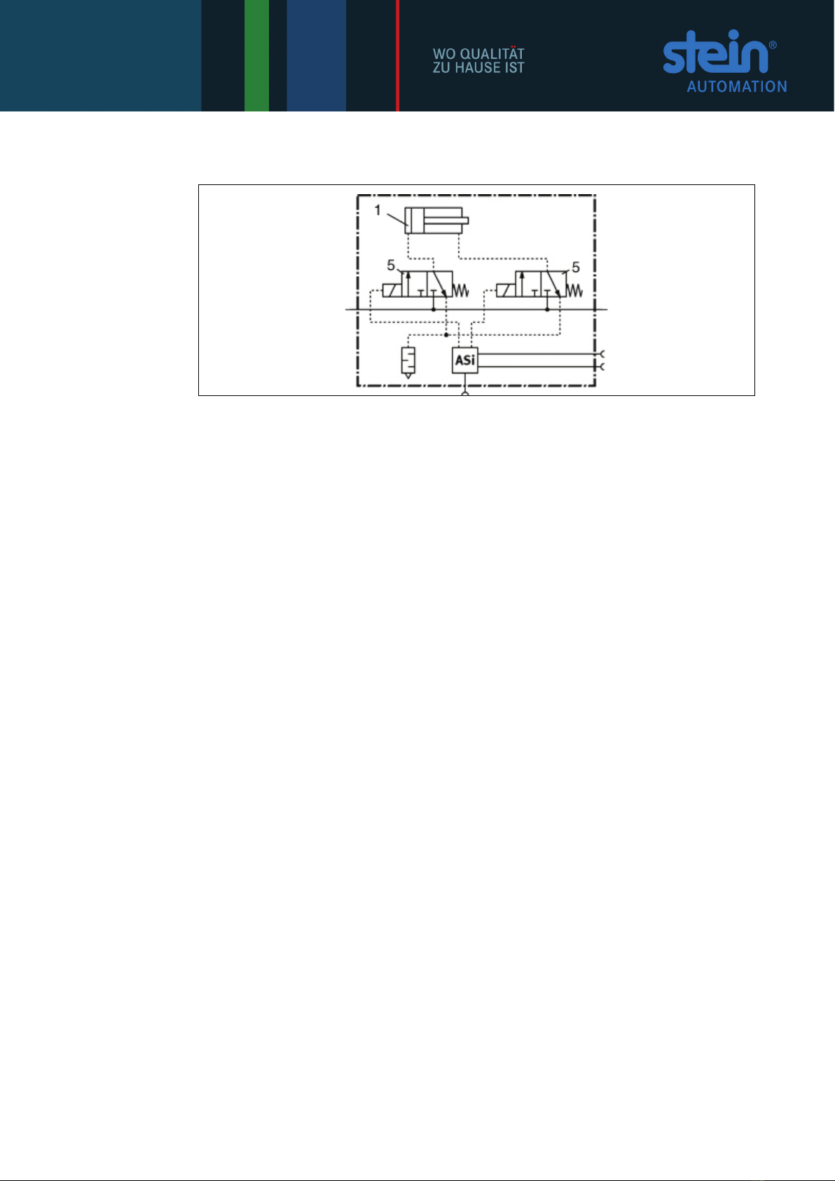
6.1 Technical data - ASI stop device
Fig. 6-2:
Pneumatic plan
1 Pneumatic stop device
(stopper latch
up/down)
2 Pneumatic valves
Electric data
Permitted address range 00 ... 31 (factory setting 00)
Supply 26.5 … 31.6 VDC
Residual ripple ≤ 20 mVss
Standby current max. 20 mA
Operating current max. 250 mA
(incl. power consumption of the sensors)
ASI profile ID=FHID2=EH
ID1=FHID=BH
S-B, F, E
Watchdog inactive
Data bit allocation D0 actuator à1 retract energized valve coil
0 valve coil is switched off
D1 actuator à1 extend energized valve coil
0 valve coil is switched off
D2 actuator à1 sensor 1 output signal 1
0 sensor 1 output signal 0
D3 actuator à1 sensor 2 output signal 1
0 sensor 2 output signal 0
Connections
ASI Plug max.1, PIN 1 ASI+, PIN 3 ASI-
Sensors Sockets with snap collar M8
Pin assignment as per DIN-EN-60947-5-2
Positive switching PNP 24 VCD
Logic level IN 11 V … 30 V OUT 0 V … 5 V
Pin assignment sensor connection
1. 24 V
3. 0 V
4. Input In-1

STEIN300 SoftMove_Stop Devices_08_GB.doc / 10.2018 17
7Installing the stop devices
The following installation description relates to the installation
•of the stop device and
•The stop device with centring rails.
The stop device and the centring rails are mounted directly inside on the belt profile of
the belt element.
7.1 Procedure
The installation procedure can be divided into 5 phases:
Preparation,
Installing the stop device/centring rails/ and sensors,
Connecting the stop device and sensors to the electrical power supply,
Connecting the stop device to the compressed air supply,
Fitting the safety equipment (covers).
i Please observe the design and measurements of the standard stop situation (stop posi-
tion) (see Chapter 5.1).
WARNING
On operating stations which generate shavings (for example drilling or thread-cutting
machinery), covers should be installed to avoid shavings or cooling fluid coming into
contact with the belt elements or the stop device.
i
Further information is available from STEIN Automation.
7.2 Preparation
DANGER!
From the Workpiece Transport System starting unexpectedly.
DANGER!
HIGH ELECTRICAL VOLTAGE
Electric shock hazard
1 Before carrying out any installation or repair work, disconnect the relevant Work-
piece Transport System from its electrical power supply.
2 Disconnect the workpiece transport system from its compressed air supply
3 Put up warning signs to prevent the system being started up while installation and
repair work is being done.
4 Remove the pallets from the relevant belt element.
18 STEIN300 SoftMove_Stop Devices_08_GB.doc / 10.2018
7.3 Installing the stop device
Protective clothing must be worn
Wear your personal safety clothing: Safety footwear and safety gloves.
i Installing the stop device does not require any changes to the belt elements!
i Please observe the design and measurements of the standard stop situation (stop posi-
tion) (see Chapter 5.1).
The stop devices are mounted on the inside of the belt elements on the guide profile. The
position of the stop device in the X axis is pre-determined by the position of the work-
station at the WTS.
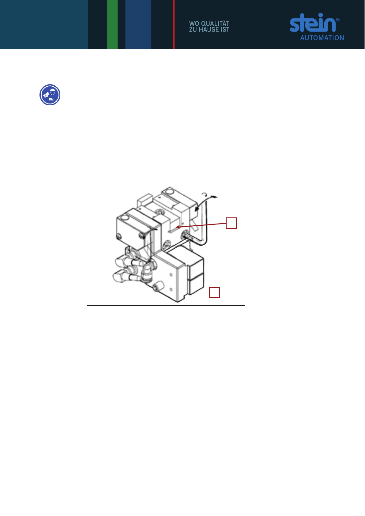
Fig. 7-1:
Stop device
1 Stop device
2 Fixing screws
To change the position of previously installed stop devices, unscrew the two fixing
screws (2) with a wrench.
Turn each of the screws one full turn counterclockwise with the wrench. This ensures
the required twisting of the groove nuts when tightening the stop device.
When the stop device is in the right position, tighten both screws (clockwise). In this
process ensure that the groove nuts twist correctly.
i Please refer to Chapter 8 and 9 for the installation dimensions and other dimensions of
the stop devices.
1
2
STEIN300 SoftMove_Stop Devices_08_GB.doc / 10.2018 19
7.4 Installing the stop devices and centring rails
The installation of the stop device for this model is the same as described under 7.3 In-
stalling the stop device.
In addition, both centring rails must also be installed on the inside of the belt elements to
the guide profile.
WARNING
The position of both centring rails depends on the position of the stop device and the
dimensions of the pallet. Please see the representation in Chapter 5.1.
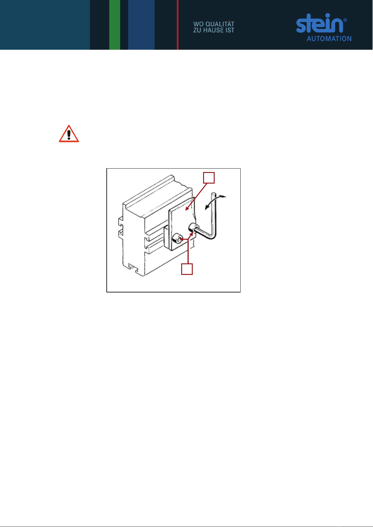
Fig. 7-2:
Centring rails
1 Centring rail
2 Fixing screws
To change the position of previously installed stop devices, unscrew the two fixing
screws (2) with a wrench.
Turn each of the screws one full turn counterclockwise with the wrench.
This ensures the required twisting of the groove nuts when tightening the centring
rail.
When the centring rail is in the right position, tighten both screws (clockwise). In this
process ensure that the groove nuts twist correctly.
2
1
20 STEIN300 SoftMove_Stop Devices_08_GB.doc / 10.2018
7.5 Connecting the stop device to the compressed air supply
WARNING!
Only specialised personnel should connect the compressed air supply!
WARNING
Carry out installation work only in a pressureless state!
WARNING
Maximum operating pressure: 6 bar.
STEIN operating pressure: 4 bar.
i Type PUN-S hoses with an exterior diameter of 6mm and wall thickness of 1mm are
used, manufactured by: Festo.
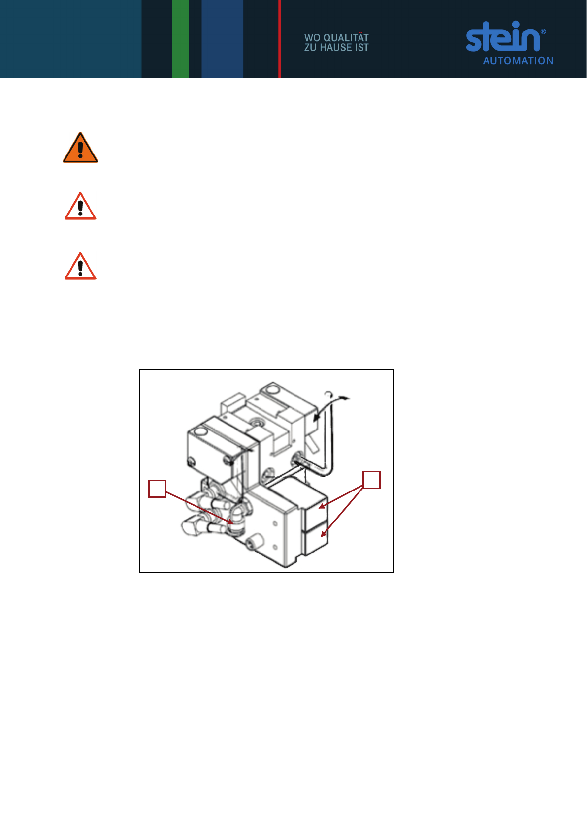
Fig. 7-3:
Connecting the stop
device to the com-
pressed air supply
1 Compressed air sup-
ply connection
2 Pneumatic valves
Connect the stop device to the compressed air supply via the compressed air supply
connection (1).
1
2
Table of contents


