Geoline GeoSystem 200 User manual

GeoSystem 200


General Information GeoSystem 200 RevA6
- 1
ENGLISH
1 INDEX
1INDEX ___________________________________________________________________________ 1
2INTRODUCTION ___________________________________________________________________ 2
3LEGEND _________________________________________________________________________ 3
4INTENDED USE ___________________________________________________________________ 3
5WARNING________________________________________________________________________ 4
6PACKAGE CONTENT ______________________________________________________________ 5
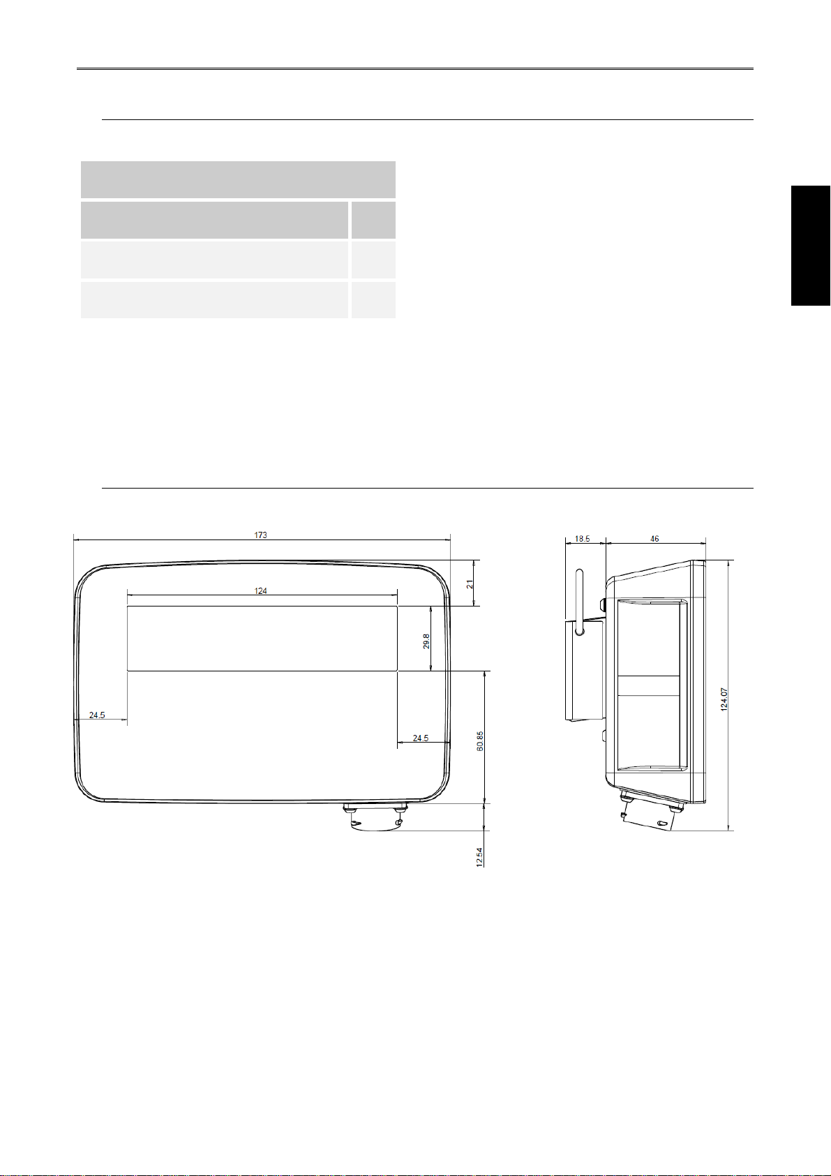
7DIMENSIONS _____________________________________________________________________ 5
8ACCESSORIES ___________________________________________________________________ 6
9TECHNICAL DATA_________________________________________________________________ 7
10INSTALLATION OF COMPONENTS ___________________________________________________ 8
10.1CONFIGURATIONS ___________________________________________________________ 8
10.2CONNECTIONS SCHEME _____________________________________________________ 10
10.3COMPUTER INSTALLATION __________________________________________________ 13
10.4SPEED SENSOR INSTALLATION_______________________________________________ 13
10.5FLOWMETER INSTALLATION _________________________________________________ 14
10.6CHECK HARDWARE INSTALLATION ___________________________________________ 14
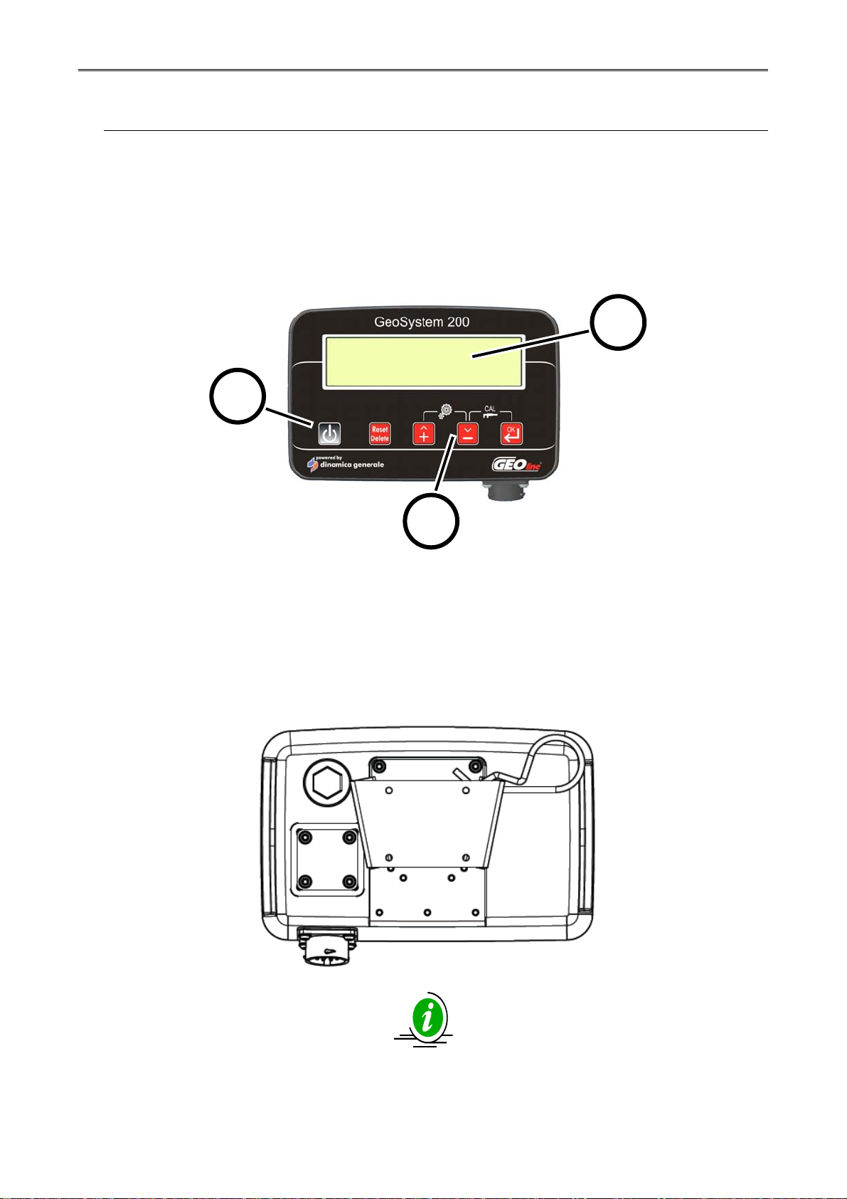
11INTERFACE DESCRIPTION OF INDICATOR ___________________________________________ 15
11.1TABLE LIST OF BUTTONS AND THEIR FUNCTIONS_______________________________ 15
11.2MENU STRUCTURE__________________________________________________________ 16
11.3CONFIGURATION GENERAL PARAMETERS _____________________________________ 17
11.3.1LIST OF MENU ITEMS OF GENERAL CONFIGURATION ________________________ 18
11.5CALIBRATION MENU ________________________________________________________ 25
11.6VALUE OF SOFTWARE PARAMETERS__________________________________________ 30
12HW TEST _______________________________________________________________________ 31
13USE OF GEOSYSTEM 200__________________________________________________________ 33
13.1DISPLAY – EXAMPLE OF VISUALIZATION WITH 4 SENSORS _______________________ 33
13.2DEFINITION OF TANK REPLENISHMENT ________________________________________ 33
13.3DEFINITION OF TREATMENT__________________________________________________ 35
13.4NEW TREATMENT___________________________________________________________ 35
13.5TURNING ON GeoSystem 200 _________________________________________________ 36
13.6TURNING OFF GeoSystem 200 ________________________________________________ 37
13.7TREATMENT _______________________________________________________________ 38
13.8TANK REPLENISHMENT USING AN EXTERNAL PUMP ____________________________ 38
13.9SETTING TANK “ZERO” LEVEL________________________________________________ 40
13.10TOTALIZERS (AVAILABLE WITH THE CONFIGURATIONS CONNECTED SENSORS OF
FLOW AND SPEED) _____________________________________________________________ 41
13.11RECALL DATA OF TREATMENTS __________________________________________ 42
14ALARMS ________________________________________________________________________ 43

General Information GeoSystem 200 RevA6
2 -
14.1WARNING AND ALARMS _____________________________________________________ 43
14.2LIST OF POSSIBLE ALARMS __________________________________________________ 43
15TROUBLESHOOTING _____________________________________________________________ 44
DICHIARAZIONE DI CONFORMITA’ UE - EU DECLARATION OF CONFORMITY - EU
KONFORMITÄTSERKLÄRUNG - DÉCLARATION UE DE CONFORMITÉ - DECLARACION UE DE
CONFORMIDAD - EU ДЕКЛАРАЦИЯ ОСООТВЕТСТВИИ ___________________________________ 45
16GUARANTEE ____________________________________________________________________ 46
“QUICK REFERENCE” GEOSYSTEM 200 _________________________________________________ 47
DISPLAY VISUALIZATION- EXAMPLE OF INDICATOR CONNECTED WITH 4 SENSORS _____ 48
ALARMS_______________________________________________________________________ 48
2 INTRODUCTION
Congratulations Dear User,
You have chosen a product by GEOline electronic, a
leading company in the development and production of electronic products for
agriculture. For years now, the international trade repays our quality,
experience, reliability and above all our technological innovation indicating an
advanced and revolutionary know how. These are the pillars of our work and
according to these beliefs we are at your service, providing you a simple but
modern, accurate and efficient product that supports you in making your work
easier for more years.This users manual intends to take you through the
different performances of the weighing system in the easiest way and to show
you some new functions as well. From configuration to use with several
optional at your disposal up to the service of defective research and to security
norms on equipments, GEOline electronic would not forget any information,
sure to offer you more support and technical assistance.
Now there is nothing left for us to do but wish you a work well done!
The team of GEOline electronic

General Information GeoSystem 200 RevA6
- 3
ENGLISH
3 LEGEND
This user’s manual uses some conventional signs, in order to lead the user during
the reading of important instructions and advices; these concern especially the
setting of the parameters of the system and thus its correct working.
Please pay attention to the following icons:
It indicates further explaining and
information.
It highly recommends to pay attention.
It indicates an operation that can be
repeated many times, cyclically.
It indicates the norms to respect.
4 INTENDED USE
Visualization system of treatment data, designed to work on agricultural machinery for crop
and orchard spraying applications.
The accurate control of the operating parameters of the sprayer or orchard system
increases the effectiveness and efficiency of the treatments, reducing the wastage of
chemicals.
!

General Information GeoSystem 200 RevA6
4 -
5 WARNING
The power supply must be connected directly to the battery or to a regulated
feeder.
The power supply must be protected with a 10A fuse.
If it is not the case, GEOline electronic is not responsible for damages to the
micro computer.
Disconnect the power supply cable from the micro computer when the battery is
undergoing recharge.
If it is not the case, GEOline electronic is not responsible for damages to the
micro computer.
Disconnect all lines from the local plant before undertaking welding on the
vehicle.
If it is not the case, GEOline electronic is not responsible for damages to the
micro computer.
For a correct functioning, please make sure that the battery has always a higher
voltage than 10, 5 Volt.
This marking on the product or on its packaging illustrates that
this product may not be disposed of with normal household
waste.
You are responsible for disposal of this equipment through a
designated waste electrical and electronic equipment
collection. To determine the locations for dropping off such
waste electrical and electronic, contact your government
office, the waste disposal organization that serves your household or the
company at which you purchased the product.
Before cleaning the agricultural vehicle with high pressure water jets, protect the
equipment from any possible water entrance. In addition, take great care not to
subject the devices, cables or any options to direct jets of water.
If the equipment needs to be cleaned, use a soft, damp, lint-free cloth. Do not
use sprays, solvents, abrasives, or sharp or pointed objects that could damage
the indicator.
!
!
!
!
!
!
!
!
!

General Information GeoSystem 200 RevA6
- 5
ENGLISH
6 PACKAGE CONTENT
Table 1- Package
7 DIMENSIONS
Picture 1 – Dimensions of indicator
8410030 - Kit GeoSystem 200
Description Qty
Indicator GeoSystem 200 1
mounting bracket 1

General Information GeoSystem 200 RevA6
6 -
8 ACCESSORIES
GeoSystem 200 may be equipped by these accessories:
ACCESSORY DESCRIPTION
Magnetic Flowmeter A sensor to noting the flow and to calculate the litres
Paddle Flowmeter A sensor to noting the flow and to calculate the litres
Pressure Sensor A sensor to measuring the pressure
Level Sensor A sensor to measuring the liquid level in the tank
Sucker hangers with mini VESA connection Hanger to fix in a glass surface
Pole mounting bracket Hanger to install the product to a pole.
CABLE DESCRIPTION
Sensor and power connection cable Cable L=5m equipped with connector for 1 sensor,
power cable (L=2m) and pump control cable.
2 sensors and power connection cable Cable L=5m equipped with connectors for 2 sensors,
power cable (L=2m) and pump control cable.
4 sensors and power connection cable Cable L=5m equipped with connectors for 4 sensors,
power cable (L=2m) and pump control cable.
Level sensor cable and power connection
cable
Cable L=5m to connect directly the level sensor ,
power cable (L=2m) and pump stop cable.
Table 2 - Accessories

General Information GeoSystem 200 RevA6
- 7
ENGLISH
9 TECHNICAL DATA
Indicator Dimensions(mm): 173x 58 x 46 (without fixing support)
Indicator weight (gr): ~ 600
Indicator Case: PA66 IGF 30 % native color RAL 9005
Indicator Protection:
IP 67
Operating temperature: -20 / +65 °C
Power supply: 9,5 – 32 Vd.c. (alarm “LOW BATTERY” < 9,5 Vdc)
Display: Alphanumeric display 16 column x 2 rows
area dimensions 123 x 30.4 mm with backlight
Display view: > 2 mt
Types of power and
connection cables: See table 2 - Accessories
Maximum relay output
absorption: 100 mA
Table 3 - Technical Data

Configuration GeoSystem 200 RevA6
8 -
10 INSTALLATION OF COMPONENTS
10.1 CONFIGURATIONS
10.1.1 Indicator GeoSystem 200
On the front side of the indicator, there are a series of keys that allow to configure the
treatment parameters and to set the relative values, in according to the type of the
installed spraying system.
Picture 2 – Indicator
1. ON / OFF key.
2. Function and setting key
3. Alphanumeric display 2 rows for 16 characters with backlight.
The system is supplied with pre-drilled mounting bracket. It is provided for a fastening
system (optional) with dedicated accessories.
Application zone of self-adhesive labels with production codes, model, and serial number.
Picture 3 - Back side of the indicator
1
3
2

Configuration GeoSystem 200 RevA6
- 9
ENGLISH
10.1.2 How to fix the bracket
Picture 4 – Bracket installation
1. Place the bracket (piece no. 1) in the side of the indicator marked with the letter A.
2. Use the screws M3x12 (pieces no. 2 and 3) provided with the kit to fix the bracket
to the box (the screws are specific for the installation of this component)
3. Fix the bracket in the fixing holes B and C using the above mentioned screws,
following the direction recommended by the dotted lines.
It is recommended to use a maximum 1,2 N m tightening torque.

Configuration GeoSystem 200 RevA6
10 -
10.2 CONNECTIONS SCHEME
10.2.1 GeoSystem 200 - system connected with 4 sensors
Option with 4 sensors: GEOline cable code: 989-0267
TECOMEC cable code: C00902038
Table 4 – Connection cables codes 4 sensors

Configuration GeoSystem 200 RevA6
- 11
ENGLISH
10.2.2 GeoSystem 200 – possible configuration of the system with 2 sensors
Option 1: GEOline cable code: 989-0451
TECOMEC cable code: C00902037
Option 2: GEOline cable code: 989-0451
TECOMEC cable code: C00902037
Option 3: GEOline cable code: 989-0451
TECOMEC cable code: C00902037
Option 4: GEOline cable code: 989-0520
TECOMEC cable code: C00902058
Option 5: GEOline cable code: 989-0451
TECOMEC cable code: C00902037
Option 6: GEOline cable code: 989-0451
TECOMEC cable code: C00902037
Table 5 - Connection cables codes 2 sensors

Configuration GeoSystem 200 RevA6
12 -
10.2.3 GeoSystem 200 – system connected with 1 sensor (flowmeter / tank level
sensor / pressure sensor / speed sensor)
Picture 5 – Possible connections between indicator and sensors
Option 1: GEOline cable code: 989-0449
TECOMEC cable code: C00902036
Option 2: GEOline cable code: 989-0266
TECOMEC cable code: C00902035
Option 3: GEOline cable code: 989-0449
TECOMEC cable code: C00902036
Option 4: GEOline cable code: 989-0266
TECOMEC cable code: C00902035
Table 6 - Connection cables codes 1 sensor

Configuration GeoSystem 200 RevA6
- 13
ENGLISH
10.3 COMPUTER INSTALLATION
10.3.1 Advice for the location
The computer GeoSystem must be positioned in the command cabin of the farm vehicle
taking care to observe the following precautions:
- Make sure that the monitor is not placed in areas subject to vibrations or crashes,
this could damage the equipment or activate the buttons unintentionally;
- Fix the device in a place that is visible and easy to reach with your hands.
- The monitor should not obstruct the movement or limit the control visibility.
10.4 SPEED SENSOR INSTALLATION
Picture 6 - Proximity Installation
10.4.1 Advice for the location
The speed sensors must be positioned taking care to observe the following precautions:
- Install the sensor at 4-5 mm away from the body to detect;
- Do not install the sensor body too near to other metal objects that may affect the
operation of the detector.

Configuration GeoSystem 200 RevA6
14 -
10.5 FLOWMETER INSTALLATION
Picture 7 - Flowmeter Installation
10.6 CHECK HARDWARE INSTALLATION
Before to start with the use of GeoSystem 200 check the correct installation of each
component:
• Check that the connectors are in the right locations
• Check that the cables have the right length
• Check that all screws are tight
• Check the polarity and the supply voltage
GeoSystem must be powered directly from the battery, it must not be connected to an
outlet controlled by a master key.
In case of use of groups of valves equipped with a calibrated return, the displayed value
corresponds to the real one only if all sections are completely open.

Configuration GeoSystem 200 RevA6
- 15
ENGLISH
11 INTERFACE DESCRIPTION OF
INDICATOR
11.1 TABLE LIST OF BUTTONS AND THEIR FUNCTIONS
Monitor with alphanumeric display and buttons
Picture 8 – Indicator
CONTROL KEYS, SELECTION OR MODIFICATION
ON / OFF key:
Turn on / off the indicator
Key command:
- It returns to the previous menu
- It enables and disables the hold function
- Holding down this button for more than 5 seconds, it reset the counters of
the current treatment
UP key:
- It flows through the individual entries to the previous menu
- Increase the value of the parameter
During the modification of parameters, pressing the button permit to
increase quickly the input values
DOWN key:
- Scrolls through the individual items through to the next menu
- Decrease the value of the parameter
During the modification of parameters, pressing the button permit to
decrease quickly the input values
Confirm key:
- Confirm the access to the selected menu or parameter value previously
modified
- Holding down this button for more than 2 seconds, it display the values of
the stored treatments

Configuration GeoSystem 200 RevA6
16 -
11.2 MENU STRUCTURE
GeoSystem 200 menu are shown in the figure, in order to enter in the various items press
the buttons or combinations of buttons located on the front panel of the monitor.
Picture 9 – Menu map

Use GeoSystem 200 RevA6
- 17
ENGLISH
11.3 CONFIGURATION GENERAL PARAMETERS
Allows to set the parameters necessary for the proper operation of the indicator.
1
Turn on by pressing .
2 The first message “GEOline GeoSystem
200” will appear on the display
3 It shows the Firmware revision and the
system name: Sprayer.
4 Then, it appears the message “Please
Wait”
5 Working values depends on installed
sensors.
6
Keep pressing simultaneously
and in order to enter in the
configuration menu.
7 Scroll through the menu items using the
and keys.
8
Press the key in order to modify
the parameter: through the and
keys is possible to change the
value.

Use GeoSystem 200 RevA6
18 -
If the fields contains default values or names, they will be displayed recursively by
pressing and keys.
If the input value is numeric, it will be increased or decreased according to the duration
of the key press with an exponential interval.
It is possible to cancel the current selection or return to the previously menu by
pressing the key.
11.3.1 LIST OF MENU ITEMS OF GENERAL CONFIGURATION
1 Language:
Italian/English/Spanish/French/German/
Portuguese/ Finnish/Russian/Polish.
2 Units:
Metrics (l/ha, Km/h, bar) / US (GPA,
mph, psi).
3 Vehicle identification:
(1-5) it identifies the vehicle on which
the system is installed.
* By entering this configuration, you set
the parameters for that particular vehicle
(in this example: vehicle 1).
4 Connected sensors:
It identified the number and the type of
sensor connected to the indicator:
Level, Flowmeter, Speed, Pressure,
Flow+Level, Speed+Pressure,
Flow+Pressure, Flow+Speed,
RPM+Level, RPM+Pressure, All
sensors (Flow, Speed, Pressure and
Level).
Table of contents