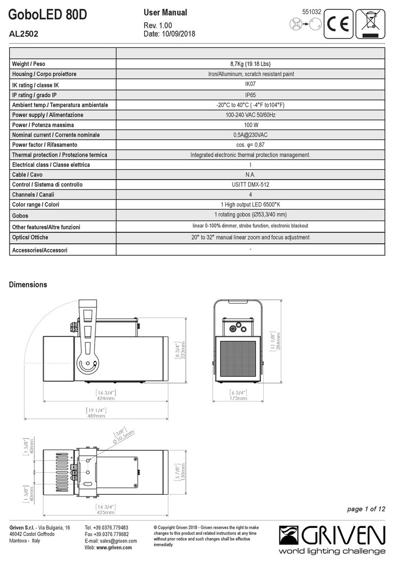
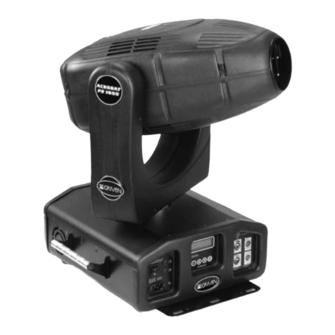
Griven KOLORSTREAM GR 0418 User manual

Foglio di Istruzioni
Owner’s Manual
KOLORSTREAM
GR 0418 HMI 2500 W
FI-0418 Rev. 0
31-07-2000

INDICE
INDICE
Pag.
1.0 CONTENUTO DELL’IMBALLAGGIO 3
2.0 SICUREZZA 3
3.0 INSTALLAZIONE DEL PROIETTORE 3
3.1 Montaggio della Lampada 3
3.2 Posizionamento del Proiettore 4
3.3 Installazione 4
3.4 Installazione con ballast separato 5
3.5 Collegamento elettrico 5
4.0 USO DEL PROIETTORE 5
4.1 Lettura del display ed uso dei comandi 5
4.2 Opzioni 6
4.3 Funzionamento con DMX 6
4.4 Posizionamento dei cavi DMX 7
4.5 Indicazione dei canali 7
5.0 FUNZIONAMENTO IN AUTOMATICO 8
5.1 Master Slave 9
6.0 MANUTENZIONE 9
7.0 INFORMAZIONI TECNICHE 10
8.0 PARTI DI RICAMBIO 10
INDEX
INDEX
Page
1.0 PACKING 11
2.0 SAFETY 11
3.0 INSTALLATION 11
3.1 Fitting the lamp 11
3.2 Mounting position 12
3.3 Mounting 12
3.4 Separate ballast set-up 13
3.5 Electrical connection 13
4.0 USE OF THE LANTERN 13
4.1 Display and control panel use 13
4.2 Options 14
4.3 DMX function 14
4.4 DMX input and output connection 15
4.5 Channel indication 15
5.0 AUTOMATIC MODE 16
5.1 Master Slave 17
6.0 MAINTENANCE 17
7.0 TECHNICAL INFORMATION 18
8.0 SPARE PARTS 18

1.0 CONTENUTO DELL’IMBALLAGGIO
Controllate attentamente il contenuto del cartone e, in caso di danni al prodotto, contattate il Vs.
trasportatore. Nell’imballaggio del presente proiettore sono contenuti i seguenti prodotti:
n° 1 Foglio di Istruzioni
n° 1 proiettore KOLORSTREAM
n° 2 spine XLR 3 poli (1 maschio+1 femmina);
n°1 presa di alimentazione
2.0 SICUREZZA
Prima di effettuare qualsiasi operazione sul proiettore, sconnettere fisicamente la linea di alimenta-
zione staccando la spina (ad esempio durante la sostituzione della lampada).
Questo proiettore è stato progettato per utilizzi in ambienti interni ed esterni. La temperatura
ambiente massima non deve superare i 50°C.
Attenzione: la temperatura della superficie esterna del vetro del proiettore può raggiungere 200°C.
Attenzione: lampada molto calda, prima della sostituzione attendete almeno 20 minuti.
Nel caso in cui il proiettore venga appeso, si raccomanda l’utilizzo della catena di sicurezza da fis-
sare al proiettore ed alla struttura di sospensione dello stesso per evitare la caduta accidentale del
proiettore, nel caso poco probabile che il punto di fissaggio primario dovesse cedere.
3.0 INSTALLAZIONE DEL PROIETTORE
3.1 Montaggio della lampada
1) Aprite lo sportello porta-vetro svitando le 4 viti situate nella parte anteriore del
proiettore (A fig.1);
2) Dopo averla sgrassata con l’apposita salvietta detergente, inserite la lampada nel portalampada
con le dovute precauzioni:
- non toccate la lampada con le dita e con stracci unti o comunque sporchi;
- non scuotete la lampada e non fatela urtare contro la lamiera del proiettore o altri oggetti;
3) Fissate saldamente la lampada al portalampada;
4) Richiudete lo sportello porta-vetro.
fig.1
fig.2
A
3

3.2 Posizionamento del proiettore
KOLORSTREAM è dotato di una base d’ appoggio che permette una stabile collocazione a terra.
Per l’installazione a soffitto, si raccomanda di ruotare la forcella attorno al corpo-proiettore di
180° (fig.1 e 2); lo scopo di questa operazione è mantenere il gruppo ventola nella parte inferiore
del proiettore (B fig.4) al fine di garantirne l’impermeabilità.
Mantenere una distanza dalla parete o dalle pareti di almeno 50cm per favorire la libera circolazio-
ne dell’aria intorno al proiettore e contenerne il riscaldamento.
3.3 Installazione
Per il fissaggio del proiettore al pavimento, oppure al soffitto, è possibile utilizzare i fori Ø 12mm
posti sulla staffa di fissaggio del proiettore oppure quelli posti sulle staffe di fissaggio del ballast,
gli interassi delle forature sono rappresentati nelle fig.3 e 4.
fig.1
B
fig.2
fig.4
A
fig.3
4

3.4 Installazione con ballast separato
E’ possibile, per praticità, separare il ballast dal proiettore. Per eseguire questa operazione svitate
le 4 viti M8 testa esagonale che fissano il ballast alla forcella del proiettore e per assicurare l’im-
permeabilità al gruppo alimentatori riposizionate le viti nella loro sede (A fig3).
Per un’installazione di questo tipo è necessario un cavo per la connessione ballast-proiettore dispo-
nibile a richiesta.
3.5 Collegamento elettrico
1) Cablate la presa fornita con un cavo di alimentazione di sezione 3x2.5mm2minimo.
2) Collegate alla rete facendo attenzione alla tensione di alimentazione (230V - 50/60Hz).
3) La linea di alimentazione del proiettore deve essere protetta mediante corretta messa a terra e
interruttore magnetotermico differenziale avente le seguenti caratteristiche elettriche:
- corrente nominale (In) 16A - valore d’intervento (Id) 0,03A.
4) Questo proiettore dispone di rifasatori di corrente.
4.0 USO DEL PROIETTORE
4.1 Lettura del display ed uso dei comandi
Il colore del led indica lo stato del proiettore.
La luce verde indica lo stato operativo.
La luce verde lampeggiante indica l’assenza del segnale DMX.
La luce rossa indica lo stato di impostazione o modifica.
La luce rossa lampeggiante indica lo stato di settaggio del segnale DMX.
Quando il proiettore è in stato operativo il display indica il numero dell’indirizzo DMX del proiet-
tore (001 fino a quando non verrà cambiato).
Per modificare l’indirizzo DMX del proiettore premere una volta il tasto (SELECT) e agire sui
tasti (-), (+), quindi premere (ENTER).
Premere il tasto (SELECT) per visualizzare l’opzione da modificare.
Per memorizzare la modifica premere il tasto (ENTER).
Se le modifiche non vengono confermate dopo 15 secondi il proiettore ritorna allo stato operativo.
5

4.2 Opzioni:
1= Master On/OffMaster On -Funzionamento in AUTOMATICO
Master Off -Funzionamento con centralina DMX
2= Preset Colours -Raggruppa in un solo canale i colori base (Giallo, Cyan, Magenta)
3= Remote switch lamp On/Off-Permette di accendere o spegnere la lampada tramite la centralina
DMX
4= Dimmer shutter, lamp On/Off Independent setting -Permette di settare l’ accensione della
lampada e il dimmer su un indirizzo personalizzato. Per selezionarlo, premere
(Select) dopo avere impostato su ON l’ opzione 4 (il display mostra l’ indirizzo
corrente del proiettore); per vedere l’indirizzo del dimmer premere (SELECT);
agire quindi sui pulsanti (+) e (-) per visualizzarlo e premere (ENTER) per
memorizzare.
N.B.: Con questa opzione il proiettore ha 2 indirizzi diversi. Passati 15 secondi
il proiettore ritorna allo stato operativo e visualizza sul display l’ indirizzo dei
colori, che si è aggiornato automaticamente al nuovo indirizzo.
9= Test
Tenendo premuto il tasto Enter per 5 secondi si visualizza il contatore della vita lampada
Tenendo premuto il tasto Enter per 20 secondi si visualizza il contatore della vita proiettore.
Per resettare il contaore della lampada premere contemporaneamente (-), (+) ed (ENTER) fino ad
ottenere l’azzeramento del display.
4.3 Funzionamento con DMX
Il proiettore KOLORSTREAM per poter funzionare con una centralina DMX deve essere settato
in MASTER OFF. Per far questo agite sul pulsante Select, quando sul display compare la scritta
1.ON premere il tasto (+) oppure (-) per ottenere la scritta 1.OF. A questo punto premete
(ENTER) ed il proiettore è settato in MASTER OFF.
N.B.: Al momento dell’ acquisto il proiettore KOLORSTREAM è settato in Master On e fun-
ziona in automatico (vedi paragrafo FUNZIONAMENTO IN AUTOMATICO).
Tutti i proiettori KOLORSTREAM che ricevono un segnale digitale da una centralina di controllo
devono avere correttamente settato il rispettivo display. Per poter essere comandato singolarmente,
ogni proiettore dovrà essere settato come da tab.1.Ogni KOLORSTREAM occupa 6 canali.
Indirizzo 6 Canali
Proiettore 1 0 0 1
Proiettore 2 0 0 7
Proiettore 3 0 1 3
Proiettore 4 0 1 9
Proiettore 5 0 2 5
Proiettore 6 0 3 1
Proiettore 7 0 3 7
Proiettore 8 0 4 3
Proiettore 9 0 4 9
Proiettore 10 0 5 5
tab.1
6

La connessione delle prese XLR 3 poli dovrà avvenire come di seguito descritto (vedi fig.1):
pin 1—-> function GND (SHIELD)
pin 2—-> function SIGNAL -
pin 3—-> function SIGNAL +
Verificate che i fili siano correttamente collegati nel connet-
tore e che essi non ne tocchino il guscio (utilizzare filo
schermato).
4.4 Posizionamento dei cavi DMX
Al fine di assicurare l’impermeabilità dell’alloggiamento della scheda, si consiglia di posizionare i
cavi dei connettori DMX tra i due coperchi come rappresentato nelle figure 2 e 3.
4.5 Indicazione dei canali
fig.1
KOLORSTREAM
CHANNEL
1 2 3456
%
Lamp
On-Off
Dimmer
Black-Out
Strobe
Yellow Cyan Magenta Zoom
100%
OFF
A
75%
W
N
N
T
O
O
A
N
L
50%
I
E
L
Y
T
G
E
P
C
A
Y
25%
O
M
ON
0% Stand
By
fig.3
fig.2
7

5.0 FUNZIONAMENTO IN AUTOMATICO
Il proiettore KOLORSTREAM per poter funzionare in modo automatico deve essere settato in
MASTER ON. Per far questo agite sul pulsante Select, quando sul display compare la scritta
1.OF premere il tasto (+) oppure (-) per ottenere la scritta 1.ON. A questo punto premete
(ENTER) ed il proiettore è settato in MASTER ON. Il proiettore inizia a funzionare in automati-
co ed è già pronto per la scelta del programma. Premete (SELECT), sul display apparirà il
seguente messaggio: (P.01)
Selezionate il programma desiderato agendo sui pulsanti (+) e (-); tenendo
presente che sono disponibili 8 programmi descritti nella tab.1.
Agendo sul tasto (+) dopo il programma8 oppure sul tasto (-) prima del programma1 il display
mostrerà rispettivamente (C.01) oppure (C.60)
Agite sui tasti (+) e (-) per selezionare uno dei 60 colori fissi a disposizione
E’ possibile regolare la velocità del cambiocolori premendo il pulsante (SELECT); il display
mostrerà: (SP.1)
Agite sui tasti (+) e (-) per regolare la velocità. La durata dei tempi è descritta
in tab.2.
E’ possibile regolare la durata di una scena colori premendo il pulsante (SELECT) il display
mostrerà:(PA.0)
Agite sui tasti (+) e (-) per regolare la durata della scena. La durata delle
scene colore pre-impostate è descritta nella tab.3.
E’ possibile regolare l’angolo del fascio di proiezione premendo il pulsante (SELECT) il display
mostrerà:(An.0)
Agite sui tasti (+) e (-) per regolare l’angolo del fascio di proiezione. Maggiore
è il valore sul display, maggiore sarà l’angolo del fascio.
Per visualizzare la sucessione delle scene colore automatiche durante la loro esecuzione premete
ripetutamente il pulsante (ENTER).
Per selezionare un nuovo programma premete il pulsante (SELECT) e agite sui pusanti (+) e (-)
come descritto precedentemente.
P. EFFETTO
Prog.1 Rosso, Magenta,Giallo
Prog.2 Rosso, Magenta,Giallo + Bianco
Prog.3 Verde, Cyan, Giallo
Prog.4 Verde, Cyan, Giallo + Bianco
Prog.5 Blu, Cyan, Magenta
Prog.6 Blu, Cyan, Magenta + Bianco
Prog.7 Colori base
Prog.8 Colori base + Bianco
SP. Tempo posiz. Colore
12sec.
24sec.
36sec.
48sec.
5 11 sec.
6 16 sec.
7 21 sec.
8 26 sec.
91sec.
tab.1 tab.2
PA.
Durata scena colore
04sec.
1 15 sec.
2 30 sec.
31min.
4 1,5 min.
52min.
6 2,5 min.
73min.
8 3,5 min.
94min.
tab.3
8

5.1 Master-Slave
E’ possibile settare più proiettori KOLORSTREAM in modalità Slave per fare in modo che segua-
no il programma eseguito da un proiettore Master. Il proiettore Master deve essere settato in
Master ON, i proiettori Slave in Master Off (con indirizzo 1 e le opzioni 2, 3 e 4 in OFF).
Il terminale di linea consiste in una resistenza, inserita tra i due pin Signal (pin 2 e 3) del connetto-
re di uscita posto alla fine della linea DMX. Ciò consente di evitare il malfunzionamento della
linea stessa. Consigliamo una resistenza da 120 Ohm.
KOLORSTREAM può funzionare in modalità Slave dove il proiettore Master è un KOLORADO®
MK2. In questa situazione occorre tener presente che il canale 6 (ZOOM) si imposta automatica-
mente al valore 0 (angolo più stretto). In questa situazione e’comunque consigliabile impostare
come proiettore Master un KOLORSTREAM.
6.0 MANUTENZIONE
Tutti i proiettori richiedono una manutenzione regolare per assicurare la massima funzionalità e la
massima resa ottica. Seguite pertanto le seguenti istruzioni:
- pulite regolarmente gli specchi e i dicroici poiché persino un sottilissimo strato di polvere può
ridurre in modo sostanziale la resa luminosa ed alterare la compattezza del fascio;
- sostituite specchi e i dicroici se hanno subito danni visibili quali tagli, crepe e profondi graffi;
- sostituite la lampada se ha subito danni visibili o se si è deformata a causa del calore;
- controllate i collegamenti elettrici ed in particolare la messa a terra;
- sostituite tutte le parti eventualmente danneggiate;
- pulite periodicamente le ventole e tutti i filtri di raffreddamento da eventuali oggetti estranei
entrati, o dalla polvere accumulatasi all’interno; per tali operazioni si consiglia l’uso di un pennel-
lino o eventualmente di un aspirapolvere; evitate l’uso di cacciaviti o altri oggetti acuminati che
potrebbero danneggiare le ventole o altre parti del faro. E’ possibile smontare i filtri di raffredda-
mento agendo sulle 4 viti autofilettanti di fissaggio.
Master Slave Slave Slave
Master On
(1.ON)
Master Off
(1 OF)
Master Off
(1 OF)
Master Off
(1 OF)
Terminale di
linea
9

7.0 INFORMAZIONI TECNICHE
8.0 PARTI DI RICAMBIO
Tutti i componenti del proiettore KOLORSTREAM sono disponibili come parti di ricambio ed il
relativo catalogo è disponibile su richiesta.
KOLORSTREAM HMI 2500W
Dimensioni max di ingombro
proiettore
L668 x P623 x H673 mm
Dimensioni max di ingombro
ballast
L500 x P400 x H145 mm
Peso proiettore 43,5 + 30,5 (Ballast) Kg
Materiale della carcassa Alluminio
Tensione nominale 230 V
Frequenza nominale 50/60 Hz
Corrente nominale 15 A
Potenza assorbita 3000 VA
Lampada consigliata HMI 2500-SE
G 38
Sistema ottico Specchio Nichel-Rodiato, alluminato ad alta rifrazione
Fusibile per lampada 6x30 250V 20A
Fusibile per elettronica 5x20 250V 3,25A
Temperatura massima di esercizio 200 °C
Temperatura ambiente massima 50 °C
10

1.0 PACKING
Check the content of the box carefully and in case of damage contact your forwarder immediately.
The following items are included in the box:
n° 1 instructions leaflet
n° 1 KOLORSTREAM unit
n° 2 XLR 3 poles plugs (1 male + 1 female)
n° 1 mains plug
2.0 SAFETY
Even if this lantern is fitted with a safety micro-switch which automatically disconnects power as
soon as the lamp cover is opened, disconnect the lantern from mains supply before replacing the
lamp or servicing the unit.
- This projector has been designed for outdoor and indoor use. For safety operation, maximum
ambient temperature must not exceed 50°C.
- Caution: the temperature of the glass surface of the projector can reach 200°C
- Caution: hot lamp; ensure that the lamp is cold before attempting to remove it (wait for about 20
minutes)
- Caution: it is strongly recommended that a safety-chain or wire is attached to this projector and
secured to the main mounting framework to arrest the fall of the unit in the unlikely event that the
primary mounting arrangement should fail.
3.0 INSTALLATION
3.1 Fitting the lamp
1) Open the front glass panel unscrewing the 4 screws located on the front of the lantern (A pict.1)
2) Clean the lamp with a cleaning towel and fit it carefully in the lamp holder.
- avoid touching the lamp with fingers or dirty towels; do not shake the lamp;
- position the lamp towards the lamp cover to obtain the maximum light output
3) Fix the lamp to the lamp holder.
4) Put the front glass panel back and fix it in its original position.
A
Pict. 1
Pict. 2
11

3.2 Mounting position
KOLORSTREAM is fitted with a support base which allows a steady position on the floor. In
order to guarantee the impermeability of the unit, it is strictly recommended not to operate the unit
upside down. Hang the unit by a 180° rotation of the bracket provided (pict 1 and 2). The correct
ballast unit position is depicted in pict. B. In order to guarantee an easy air circulation around the
unit keep it at a minimum distance of 0,5m from obstacles and flammable objects.
3.3 Mounting
12mm Ø holes are provided in the support bracket and in the ballast base to fix the lantern to the
ceiling or to the floor (see pict.3 and 4 for wheelbases dimensions).
pict.2
pict.4
B
pict.1
pict.3
A
12

3.4 Separate ballast set-up
The unit is fitted with a separate ballast facility and the connecting cable is available on request.
To remove the ballast from the main unit, unscrew the 4 exagonal M8 screws you find on top of
the ballast housing and fix them again when the ballast has been moved away to protect it from
the ingress of water.
3.5 Electrical connection
1) Cable the provided mains plug with a supply cable of 3x2.5 mm2minimum;
2) Connect the lantern to a mains supply of 230V - 50/60Hz.
3) Ensure that the mains cable is connected to earth; the safety thermoswitch and the earth leakage
circuit breakers must have the following characteristics:
rated for (In) 16A - sensitivity (Id) 0,03 A.
4) KOLORSTREAM®is provided with power factor correction system.
4.0 USE OF THE LANTERN
4.1 Display and control panel use
The led colour indicates the projector mode.
The green led indicates the operating mode.
The red light indicates the setting or the zapping mode.
Flashing green led indicates the absence of signal DMX.
Flashing red light indicates the DMX signal setting.
When the projector is in the operating mode the display indicates the projector DMX addressing
number, which is 001 when the unit leaves the factory. In order to change the DMX addressing
number push (SELECT) then (-) or (+). When you find the desired number push (ENTER).
Push (SELECT) when you want to view or zap an option. To memorise it push (ENTER).
If options are not entered within 15 seconds the projector returns to the operating mode.
13

4.2 Options:
1= Master On/OffMaster On -AUTOMATIC MODE
Master Off -DMX MODE
2= Preset Colours -Yellow, Cyan, Magenta, all in one channel.
3= Remote switch lamp On/Off-Lamp On/Off through the DMX controller.
4= Dimmer shutter, lamp On/Off Independent setting-To enter this option push SELECT after
you have set option 4 to ON (the display shows the current projector
addressing); to view the dimmer/Shutter adressing push SELECT and then
push (+) and (-) to view the new one and push ENTER to memorise it.
Note: The unit will have now two different addressing. Within 15 seconds the
projectors returns to the operating mode and the display shows the colours
addressing which is automatically updated to the new addressing.
9= Test
Lamp life: Push ENTER for more then 5 seconds
Use meter: Push ENTER for more then 20 seconds
To reset the lamp life meter push (-), (+) and ENTER simultaneously until you get the zero set-
ting of the display
4.3 DMX function
To access the unit through a DMX controller KOLORSTREAM must be set to MASTER
OFF.Push SELECT; when 1.ON is displayed push (+) or (-) to obtain 1.OF. Now press ENTER.
Theunit is set to MASTER OFF.
Note: when the KOLORSTREAM unit leaves the factory it is set to MASTER ON and
works in AUTOMATIC MODE (See AUTOMATIC MODE section).
Every single KOLORSTREAM unit must have its own display correctly set when it is controlled
by a digital signal. Please set the display of each unit as per diagram 1 when more units are
accessed through a DMX controller. KOLORSTREAM uses 6 channels.
DMX Addressing 6 Channels
Projector 1 0 0 1
Projector 2 0 0 7
Projector 3 0 1 3
Projector 4 0 1 9
Projector 5 0 2 5
Projector 6 0 3 1
Projector 7 0 3 7
Projector 8 0 4 3
Projector 9 0 4 9
Projector 10 0 5 5
(diag.1)
14

The connection of the XLR 3 poles must be as follows: (see pict.1)
pin 1---> function GND (SHIELD)
pin 2---> function SIGNAL -
pin 3---> function SIGNAL +
Pls. ensure that the cables are properly connected.
Use shielded cable.
4.4 DMX input and output connection
In oreder to protect the PCB housing from water penetration, it is strictly recommended to posi-
tion the DMX connecting plugs as illustrated below (see pictures 2 and 3).
4.5 Channels Indication
KOLORSTREAM
CHANNEL
1 2 3456
%
Lamp
On-Off
Dimmer
Black-Out
Strobe
Yellow Cyan Magenta Zoom
100%
OFF
A
75%
W
N
N
T
O
O
A
N
L
50%
I
E
L
Y
T
G
E
P
C
A
Y
25%
O
M
ON
0% Stand
By
pict.1
pict.2 pict.3
15

5.0 AUTOMATIC MODE
KOLORSTREAM has to be set to MASTER ON to be accessed it in automatic mode. Push
SELECT, when 1.OF is displayed push (+) or (-) to obtain 1.ON. Now press ENTER . The unit is
set to MASTER ON. The unit starts working in automatic mode and is ready for the programming
procedure.Push SELECT and the following will be displayed: (P.=01)
Choose the desired programme by pushing (+) and(-);
8 programmes are available as per picture 1.
Pushing (+) after programme 8 or (-) before programme 1 the display will show relevant (C.01) or
(C.60)
Push keys (+) and (-) to select one of the 60 colours available.
Colour changing speed can be determined by pushing SELECT. When the display shows (SP.1):
push (+) and (-) to set the speed.
Colour scene and positioning length are described in picture 2.
Colour scene length can be customised by pushing SELECT.When the display shows (PA.0):
act on (+) or (-) to set the colour scene length. Pre-set colour scene length
can be checked in picture 3.
Aperture angle projection can be customised by pushing SELECT. When the display shows
(An.0):
push (+) or (-) to adjust the aperture. The higher is the value on the
display the widder is the angle degree.
To see the automatic colour scene sequence while it is automatically revolving push ENTER
repeatedly.
Push SELECT, then (+) or (-), as above mentioned, to select a new programme.
P. EFFECT
Prog.1 Red, Magenta, Yellow
Prog.2 Red, Magenta,Yellow +White
Prog.3 Green, Cyan, Yellow
Prog.4 Green, Cyan, Yellow + White
Prog.5 Blue, Cyan, Magenta
Prog.6 Blue, Cyan, Magenta + White
Prog.7 All colors
Prog.8 All colors + White
SP Positioning length
12 sec.
24 sec.
36 sec.
48 sec.
511 sec.
616 sec.
721 sec.
826 sec.
91 sec.
Pict. 2
Pict. 1
PA.
Colour scene length
04sec.
1 15 sec.
2 30 sec.
31min.
4 1,5 min.
52min.
6 2,5 min.
73min.
8 3,5 min.
94min.
Pict. 3
16

5.1 Master -Slave
More KOLORSTREAM units can be set to ‘SLAVE’ to follow the ‘MASTER’ unit in synchrony.
The ‘MASTER’ unit must be set to MASTER ON, the ‘SLAVE’ units must be set to ‘MASTER
OFF’ (with address number 1 and options 2,3 and 4 set to off).
Master Slave Slave Slave
Master On Master Off Master Off Master Off
(1.ON) (1.OF) (1.OF) (1.OF)
The line terminal is a resistor fitted between the 2 Signal Pins (2 and 3) at the end of the DMX.
line. This is to avoid the defective functioning of the DMX line. A 120 Ohm resistor is suggested.
KOLORSTREAM can also operate on ‘SLAVE’ mode when the ‘MASTER’ unit is a Kolorado
MK2 1800 or a Kolorado MK2 2500. In this contest the zoom channel (N°6) will be automatically
set to value 0 which corresponds to the narrowest beam projection. It is anyway suggested to set
the KOLORSTREAM unit as the ‘MASTER’ of the chain.
6.0 MAINTENANCE
All lanterns require regular maintenance to ensure maximum performance and light output.
Please follow these instructions:
- clean, mirrors and dichroics regularly, as even a thin layer of dust can reduce the light output and
scatter the beam;
- replace the lamp in case it is damaged or deformed;
- carefully check the electrical connections, particularly the earth connection;
- replace the lenses, the mirrors and the dichroic filters if they are visibly damaged;
- replace all the damaged components
IMPORTANT: clean regularly the fans and the grids. Don't use screw drivers or sharp objects
which may damage the fans or other parts of the lantern. The grids can be removed by unscrewing
the 4 self-tapping screws.
Line terminal
17

7.0 TECHNICAL INFORMATION
8.0 SPARE PARTS
All components for KOLORSTREAM are available.
The exploded diagram and the catalogue are available on request.
KOLORSTREAM HMI 2500W
Size L668 x P623 x H673 mm
Ballas t Size L500 x P400 x H145 mm
Weight 43,5 + 30,5 (Ballast) Kg
Body Aluminium and galvanised steel body
Operating Voltage 230 V
Operating Frequence 50/60 Hz
Operating Amperage 15 A
Power absorbed 3000 VA
Suggested lamp HMI 2500-SE
G 38
Optic System Nickel Rhodium plated reflector
Lamp Fuse 6x30 250V 20A
Electtronic System Fuse 5x20 250V 3,25A
MaxWorking Temperature 200 °C
Max Ambient Temperature 50 °C
18


WORLD LIGHTING CHALLENGE
Professional Lighting Manufacturer
Via Bulgaria, 16 - 46042 CASTEL GOFFREDO (MN)
Telefono 0376/779483 - Fax 0376/779682 - 0376/779552
Table of contents
Languages:
Other Griven Light Fixture manuals
Popular Light Fixture manuals by other brands

BARRON
BARRON Exitronix NY900U Series installation instructions

Xoop Lighting
Xoop Lighting P180 user manual

Lightolier
Lightolier Calculite C3MRL CCDFT specification

EuroLite
EuroLite LED TMH-48 user manual

Kichler Lighting
Kichler Lighting Universal Ceiling Fan Light Fixture instruction manual

Organic Lighting
Organic Lighting liniLED Diffuse Top 1/2" user manual